Table of Contents
Advertisement
Quick Links
Advertisement
Table of Contents
Troubleshooting

Related Manuals for THORLABS BC106-VIS


Summary of Contents for THORLABS BC106-VIS
- Page 1 Thorlabs Beam Beam Analyzing Software BC106-VIS BC106-UV Operation Manual 2011...
- Page 2 Version: Date: 11.04.2011 © 2011 Thorlabs © 2011 Thorlabs...
-
Page 3: Table Of Contents
Ambient Light Correction ................................. 66 Hot Pixel Correction ................................. 67 Measurement Results ................................. 69 Save Measurement Results ................................. 70 Pow er Ranges ................................. 75 Pulsed Laser Sources ................................. 76 No Trigger ..............................76 Softw are Trigger ..............................76 © 2011 Thorlabs... - Page 4 Numerical Results ..............................123 Part IV Computer Interface 1 Libraries ........................... 126 2 Sample Programs ........................... 128 3 Thorlabs Beam Library ........................... 131 Part V Maintenance and Repair 1 Version and other Information ........................... 132 2 Warnings and Errors ........................... 132 3 Cleaning ...........................
- Page 5 ..............................155 BC106-VIS ..............................156 BC1M2 Mounting Adapter ..............................157 Translation Stage VT-80 ..............................158 5 Thorlabs "End of Life" Policy (WEEE) ........................... 159 Waste Treatment on your ow n Responsibility ................................. 159 Ecological Background ................................. 159 6 Listings ........................... 160 List of Acronyms .................................
-
Page 6: Foreword
ATTENTION Paragraphs preceeded by this symbol in the manual explain hazards that could damage the instrument and connected equipment or may cause loss of data. NOTE This manual also contains "NOTES" and "HINTS" written in this form. © 2011 Thorlabs... -
Page 7: Part I General Information
Do not cover the Beam Profiler in order to prevent heating the instrument. Changes to single components may be carried out or components not supplied by Thorlabs be used. Only with written consent from Thorlabs may This precision device is only transportable if duly packed into the complete original packaging. -
Page 8: Part Ii Getting Started
1 Distribution CD-ROM 1 BC106 Operation Manual 1 SM1BC Adapter Preparation 1. Install the Thorlabs Beam software to your computer as described in Software Installation 2. Connect the camera using the supplied USB cable to the PC as described in Connection to the PC 3. - Page 9 Please, install the software prior to connect the instrument to your PC via USB interface. Use only the supplied high speed (USB 2.0) cable, not full speed (USB 1.1) cables or thin profile cables with increased resistance, this can cause transmission errors and improper instrument operation! © 2011 Thorlabs...
-
Page 10: Operating Elements
The Beam Profiler provides at the bottom side a mounting plate with 2 holes and different thread - M6 (ahead) and UNC8-32 (rear). Mount the Beam Profiler on your optical board using Thorlabs post, post holder and base. See Accessories... -
Page 11: Filter Wheel
1x 40 dB VIS, absorptive 1x 40 dB VIS, absorptive Model BC106-VIS is equipped with four absorptive neutral density (ND) filters made from glass, that's why they are applicable only for the visible and near infrared wavelength range 350 - 1100 nm. - Page 12 Thorlabs Beam 4.0 The nominal filter loss and also the appropriate wavelength range (UV / VIS) is engraved to the filter housing. Note that the filter loss is wavelength dependent and may diverge largely from its nominal value, especially for operating wavelengths at the border of the Beam Profiler wavelength range.
-
Page 13: Connectors
Mini B USB connector, labeled with USB symbol For connection to your PC, see chapter Connection to the PC TTL Trigger input, labeled with For synchronizing a Pulsed Laser Sources to the Beam Profiler, see Trigger Input for specifications. © 2011 Thorlabs... -
Page 14: Trigger Input
Thorlabs Beam 4.0 2.4.4 Trigger Input An electrical TTL trigger input is provided for synchronizing the Camera Beam Profiler's global shutter to Pulsed Laser Sources . The appropriate BNC connector is situated on the left side of the instrument body, see... -
Page 15: Part Iii Operating The Beam Profiler
3.2.1 Software Installation Insert the "Thorlabs Beam CD 4.0" (or higher) CD-ROM in your CD/DVD drive. It automatically starts up and displays the installation start screen. In case this 'auto start' feature is disabled on your computer please execute the "Autorun\Autorun.exe"... - Page 16 Thorlabs Beam 4.0 Installation ® The following procedure is described for installation to a Windows 7 operating system. Click to the first topic. It is recommended to follow the recommended path, click Next. © 2011 Thorlabs...
- Page 17 Operating the Beam Profiler Please read this license agreement carefully, choose "I agree" and click 'Next'. Click "Next", the software installation starts. © 2011 Thorlabs...
- Page 18 You may check the box "Always trust software from "Thorlabs GmbH", this will shorten the installation. However, if you do not want to do that, please click the "Install button. Thorlabs USB driver is now installed. Further, you will be asked to confirm the © 2011 Thorlabs...
- Page 19 Operating the Beam Profiler installation of another two device software. Please proceed as described above. © 2011 Thorlabs...
- Page 20 Thorlabs Beam 4.0 Now, the Beam software including device drivers is installed to your computer. Click "Next", and "Close" to complete the software installation. After finishing, the installer runs a check for installed NI-VISA Runtime. If you have a Version 4.x up already installed to your computer, you can proceed immediately with...
- Page 21 Operating the Beam Profiler Click to "NI-VISA Runtime 5.0.2." The NI Installer comes up. Click "Next" © 2011 Thorlabs...
- Page 22 Thorlabs Beam 4.0 It's recommended to install NI-VISA to the proposed folder, click "Next" In this screen the required components are being selected. USB is required for the Beam Profiler control, Serial (RS232) for control of the translation stage used for M²...
- Page 23 Operating the Beam Profiler Please read the Software License Agreement carefully, choose "I accept" and click "Next" Please read the License Agreement carefully, choose "I accept" and click "Next" © 2011 Thorlabs...
- Page 24 Thorlabs Beam 4.0 Click "Next", the software installation starts and may take a few minutes. Click 'Finish'. The installation has completed successfully. © 2011 Thorlabs...
-
Page 25: Connection To The Pc
Device Manager of your computer. From the Start button select Control Panel Device Manager The following entry under the USB-Devices group indicates that the Thorlabs Camera Beam Profiler device is properly installed. If you cannot see such an entry please check the troubleshooting chapter. -
Page 26: Start The Application
Start the Application Access the Application Programs from the START button. Click the "Programs" "Thorlabs" "Thorlabs Beam Application" entry. Or simply click the appropriate symbol added to your desktop. When the application is started the first time or if the last used camera is not connected to your system the following 'Device Selection' dialog will appear: Usually the Beam Profiler connects automatically to the first connected camera. - Page 27 When the Beam Profiler application is started the first time, three preselected windows are opened and arranged automatically. Otherwise, the arrangement of the last session (selected windows and its position) will be recovered. See chapter Child Windows for a detailed description of each window. © 2011 Thorlabs...
-
Page 28: The Graphics User Interface (Gui)
Thorlabs Beam 4.0 The Graphics User Interface (GUI) 3.3.1 GUI Overview The main window consists of a menu bar, a tool bar, a status bar and common frame for displaying several child windows. A: Menu bar All user activities can be done with items in the menu bar. - Page 29 The "Clear Windows" function resets the content of all windows, including child windows. With the receive of the next measurement result from the instrument, the window content is filled. This function may be useful in combination with a trigger © 2011 Thorlabs...
- Page 30 Thorlabs Beam 4.0 mode while waiting for the next image orfor a synchronous restart of all plots and time-based measurements. Start NI Network Variables Note In order to use this command, you need to have installed additional National ® Instrument software (Distributed System Manager, NI Runtime Engine).
- Page 31 The first entry 'Contents' within the help menu or Key 'F1' will open the online help file which contains the complete information of this manual. With a click on the link Visit the Thorlabs Website the Thorlabs website is opened in the standard browser.
- Page 32 Thorlabs Beam 4.0 If you have trouble with the software, please submit the version of the application to Thorlabs. This is helpful for resolving your problem. © 2011 Thorlabs...
-
Page 33: Child Windows
"2D Projection ", "3D Profile " and the "Calculation Results ". The application provides further windows: "X Profile ", "Y Profile ", "Plot Positions ", "Plot Power ", "Plot Gaussian Fit ", "Beam Stability " and " © 2011 Thorlabs... - Page 34 ". All these windows can be opened and closed with the symbols in the toolbar or via the entries in the menu "Windows". The appearance of the Thorlabs Beam software can be arranged according to somebody's requirements and taste. All child windows can be sized and positioned very flexible.
-
Page 35: Projection
The reference position can be either the center of the sensor, the center of the region of interest, the peak position, the centroid position or a user defined position which can be set in reference position edit mode. © 2011 Thorlabs... - Page 36 Thorlabs Beam 4.0 Toolbar Icon Associated Action Defines the Calculation Area which is a subarea of the visible camera image which is itself defined by the ROI (see Device Settings ). Only pixels within this Calculation Area are interrogated and recognized for beam data calculation.
- Page 37 2D Projection window. But, in order to limit the image interrogation to the main beam the calculation area was chosen much smaller. Within this 2D Projection panel, coordinates X and Y are defined as follows: © 2011 Thorlabs...
-
Page 38: 3D Profile
Thorlabs Beam 4.0 Independent of the selected unit (pixel or µm) within the Application Settings panel (see Application Settings ) the origin of the coordinate system is the selected reference position. Horizontal axis is X and vertical axis is Y. Both axes are also labeled onto the Beam Profiler housing. -
Page 39: X,Y Profiles
Each of the two windows can be opened and closed via the menu item "X Profiles" or "Y Profiles" in the window menu or clicking on the appropriate toolbar symbols. The windows can also be closed via the X button in the upper right corner of the child window. © 2011 Thorlabs... - Page 40 Thorlabs Beam 4.0 The X profile displays a single pixel row taken from the received camera image, whereas the Y profile shows a single pixel column. The column and row is defined by the position of cross hair within the 2D Projection graph.
-
Page 41: Calculation Results
There is also the possibility to change the units for the calculations. The width of the columns is predefined but can be resized. All measurement parameters are described in chapter Measurement Results © 2011 Thorlabs... -
Page 42: 3.3.2.4.1 Pass/Fail Test
Thorlabs Beam 4.0 3.3.2.4.1 Pass/Fail Test The Calculation Results panel includes a pass/fail test. For each parameter a minimum and maximum can be set. Pass/Fail test result will be displayed only for those parameters, where the appropriate box in Pass/Fail column is checked. -
Page 43: Plots
To load test parameter from a file push the "Load Test Parameter" button and select the test parameter configuration file. Plots 3.3.2.5 Thorlabs Beam software offers several additional plot windows to show the beam behaviour: Plot Positions Plot Power Beam Stability... -
Page 44: 3.3.2.5.1 Plot Positions
Thorlabs Beam 4.0 Cursor mode: If the mouse position is near to the vertical cursor line, the mouse cursor changes to . The cursor line can be moved with the left mouse button pressed to a position inside the diagram. The current values at the cursor position are shown in a rectangle next to the cursor in the colors of the plotted curve. -
Page 45: 3.3.2.5.2 Plot Power
The total power measured by the beam profiler vs. time can be displayed. Note Thorlabs Beam Profiler instruments are not calibrated for power wavelength dependent. The power calculation is based on a typical responsivity curve of the used sensor and manually entered wavelength (see... -
Page 46: 3.3.2.5.3 Plot Gaussian Fit
Thorlabs Beam 4.0 3.3.2.5.3 Plot Gaussian Fit Menu bar: Windows -> Plot Gaussian Fit This window plots the Gaussian Intensity value (see Calculation Results ) which shows the coefficient of determination of the fit. Toolbar Associated Action Icon Opens a dialog box to specify the properties of the saved screenshots / diagrams. -
Page 47: 3.3.2.5.4 Plot Orientation
This windows plots the orientation (in degrees) of the ellipse, see Calculation Results Toolbar Associated Action Icon Opens a dialog box to specify the properties of the saved screenshots / diagrams. Toggle button to display grid in the diagram. Auto scale Show or hide the cursor © 2011 Thorlabs... -
Page 48: 3.3.2.5.5 Beam Stability
Thorlabs Beam 4.0 3.3.2.5.5 Beam Stability Toolbar: Menu bar: Beam Stability Count: The actual count of displayed measurement results. Max Count: Max count limits the number of displayed measurement points. If the actual count reached the entered max count value (here: 100), in the diagram will be displayed the recent 100 measurement results, previous results will be deleted. -
Page 49: Save Settings
This is to see the full aperture range and full amplitude range on every start of the GUI. Note The stop state of the previous measurement will be ignored at a new start of the Beam software because it always starts in continuous mode. © 2011 Thorlabs... -
Page 50: Measurement With The Beam Profiler
Thorlabs Beam 4.0 Measurement with the Beam Profiler General guidelines for operating the Camera Beam Profiler BC106 You should follow these basic guidelines to achieve correct and reliable measurement results. 1. Provide stable Mounting to the Beam Profiler using the appropriated threads on its base plate. -
Page 51: Operating The Instrument
. During initial program start a Device Selection panel will be displayed. On tab "Device Selection" mark the instrument "BC106-UV" or "BC106-VIS" within the device list you want to work with. Use the device type (UV/VIS) as well as the Serial Number for device identification. -
Page 52: Device Settings
Thorlabs Beam 4.0 application is started the first time, three child windows are opened and arranged automatically. The user can open and close child windows via the entries in the menu "Window" or via the symbols in the toolbar of the main window. - Page 53 ND filter within the Filter Wheel (the nominal attenuation value is written on the filter holder). 3. If this camera is connected the first time, the following default values are set for the camera parameters: © 2011 Thorlabs...
- Page 54 Thorlabs Beam 4.0 Parameter Default value Region Of Interest Full Size Tab Beam Profiler Parameter Wavelength 635nm Filter Wheel Selection [dB] No Filter (0 dB) Auto Exposure Control Gain 1.0 (minimum) AD Precision mode FAST (8 bit data) Tab Corrections...
- Page 55 To shift the selected ROI within the available sensor area click right into this rectangle and drag the mouse. You may also chose a user defined ROI. Just draw a rectangle into the preview © 2011 Thorlabs...
- Page 56 Thorlabs Beam 4.0 image by clicking left while dragging the mouse from the upper left corner to the lower right corner. The last preset value is replaced automatically by "User defined" and the chosen ROI size and position is displayed within the controls on the right.
- Page 57 Operating the Beam Profiler BC106-VIS, respectively. Filter wheel selection There are in total 4 different neutral density (ND) filters available by rotating the filter wheel in front of the Beam Profiler aperture. See chapter Filter Wheel for details. You need to enter the nominal attenuation of the chosen ND filter in order to be recognized for calculating the Total Power.
- Page 58 Thorlabs Beam 4.0 even required to disable the automatic exposure control and set the optimal values manually. For this, remove the 'Auto Exposure Control' check mark. Manual Exposure Control Exposure time is the period of time in which the global shutter is open and the image sensor is exposed.
- Page 59 Therefore a manual or automated black level adjustment is dispensable. Since an increased sensor's dark level would have the same effect like uniformly distributed ambient light, the provided ambient light correction (see above) will also © 2011 Thorlabs...
- Page 60 Thorlabs Beam 4.0 eliminate a remaining dark level. Trigger The electrical TTL level trigger input is used to synchronize laser pulses to the camera exposure time. See chapter Pulsed Laser Sources for a detailed description of the implemented trigger functionality.
-
Page 61: Application Settings
That is, pixels inside the ROI, but outside the Calculation Area are displayed but not used for calculations! Such a limitation is especially advantageous for: Selecting and analyzing only a single beam spot among multiple beams Rejecting ambient or stray light © 2011 Thorlabs... - Page 62 Thorlabs Beam 4.0 Reducing measurement noise Increasing performance Note It is advisable to set the camera ROI to the smallest feasible area instead of working with a large ROI and shrinking the Calculation Area afterwards. This will increase measurement speed.
- Page 63 Input values are valid from 5% to 95%. Click on Default (1/e²) to set the default Clip Level of 13.5%. See Appendix Application Note for details. Set Averaging over frames to numbers higher than 1 to enable noise reduction. © 2011 Thorlabs...
- Page 64 Thorlabs Beam 4.0 The chosen number of frames are averaged and only the averaged frame is displayed and calculations are applied to it. This option is helpful under instable light sources with fluctuating intensity or beam shape and if the update rate on the screen is too high for easy data readout. Also use this option to suppress Beam Profiler camera noise in case of low intensity.
- Page 65 The application loads valid *.lut files from the folder ...\My Documents\Thorlabs\Thorlabs Beam\LUT A valid *.lut file is an ordinary text file with nine columns and 256 rows. Values have to be tab-separated. The first three columns have 256 entries, the last six columns only 128.
- Page 66 Thorlabs Beam 4.0 ... stands for the intermediary values. © 2011 Thorlabs...
-
Page 67: Power Correction
When such a Power Correction was performed once successfully the appropriate calibration value is stored within the Beam Profiler instrument so that the check mark will become active as soon as the instrument is initialized new. © 2011 Thorlabs... -
Page 68: Ambient Light Correction
Make sure the laser is blocked, but not the ambient light, click "OK"; the correction starts. Note Thorlabs Beam software uses a unique approach for Ambient Light Correction - please see details in section Application Notes When ambient light power is changed or a different ND filter is used, a new... -
Page 69: Hot Pixel Correction
Hot pixels can be displayed in 3D view (auto scale to peak disabled), either: Thorlabs Beam offers a hot pixel correction feature. Start the Device settings from Menu "Options" or from the appropriate icon. From the right tab choose Corrections and start hot pixel correction by clicking the Start Correction button: ©... - Page 70 Thorlabs Beam 4.0 The correction starts; hot pixels are being smoothed by interpolation to adjacent pixels and a maximum of 100 hot pixel can be saved. After completing, the box "Hot Pixel Correction" will be checked. Hot pixel correction data are saved to the camera's internal non-volatile memory and remain there unless overwritten with the next hot pixel correction.
-
Page 71: Measurement Results
Location: units pix and µm are available Quantization: digit, mW or dBm are available Units specified for the calculation (e.g. Gaussian fit is always in per cent, degree for angles) Change the units in the appropriate Application Settings Overview on all available units: © 2011 Thorlabs... -
Page 72: Save Measurement Results
Thorlabs Beam 4.0 Unit Description Location, width or distance in camera pixels. The origin of the coordinate system (X=0, Y=0) is the sensor center not the image center!. Positive X values go to the right, positive Y values to the top of the image. - Page 73 Beam Software: A data file cannot be imported in order to reconstruct a beam profile. Intensity values are saved to a text matrix with a header: The 1st value in the 1st line represents the intensity of the left upper pixel in the 2D projection. © 2011 Thorlabs...
- Page 74 Thorlabs Beam 4.0 Sequential Saving By checking the Sequential Saving box, a series of measurement data can be saved. The same data formats can be chosen as for Export of Device Data The saving can be proceeded with a defined time interval (0 to 100.00 sec) or for...
- Page 75 The results of the measurement are saved to a compact test protocol. It contains the Beam Profiler data and settings, numerical calculation results as well as the 2D Projection and the 3D Profile windows, so far these windows were displayed. © 2011 Thorlabs...
- Page 76 Thorlabs Beam 4.0 Example: © 2011 Thorlabs...
-
Page 77: Power Ranges
Maximum and minimum applicable power depends on beam diameter and the selected optical filter and wavelength. The wavelength of maximum response is chosen: for BC106-VIS 550 nm, for BC106-UV 200 nm. Both unbroken lines indicate the BC106 power range without any filter applied. -
Page 78: Pulsed Laser Sources
Thorlabs Beam 4.0 3.4.10 Pulsed Laser Sources Overview The BC106 Camera Beam Profiler is able to capture beam profiles in different trigger modes. Basically, you can work using a continuous or single shot mode. Use these control buttons in the toolbar to enable one of these modes and click to pause image acquisition. - Page 79 Software Trigger. Although a continuous image capturing is performed in the background, the first image fulfilling the software trigger condition will stop this process and the appropriate image is displayed and interrogated. © 2011 Thorlabs...
-
Page 80: Hardware Trigger
Thorlabs Beam 4.0 3.4.10.3 Hardware Trigger Hardware Trigger is suited for pulsed light sources which provide an electrical trigger signal for synchronization to the Beam Profiler. An additional trigger delay can be programmed to align the profiler’s exposure time exactly to the occurrence of a single or a repetitive light pulse. - Page 81 When entering a desired delay to the box ‘Target Delay’, the software displays the resulting ‘Actual Delay’ as the closest possible value. Example for exposure time = 0.020ms (20µs): Target Delay Actual Delay 0.000 ms 0.096 ms 0.050 ms 0.096 ms 0.100 ms 0.100 ms © 2011 Thorlabs...
- Page 82 Thorlabs Beam 4.0 Repetitive Pulses This Trigger mode is helpful suited for pulsed light sources which - provide an electrical TTL level trigger output signal - generate pulses with duration shorter than the internal trigger delay of the Beam Profiler - have a constant repetition frequency, i.e.
-
Page 83: Beam Quality (M²) Measurement
Not only the focusing optics but mainly the quality of the light source itself has influence to the focusability. A high beam quality is a pre-condition for optimal focusability. What is Beam Quality Beam Quality and its direct influence to focusability is a very important feature of lasers. © 2011 Thorlabs... - Page 84 Thorlabs Beam 4.0 Beam Propagation Measurements according to ISO 11146 standard disclose beam quality and describes it as a single value either the Times-Diffraction-Limit Factor M (also known as beam quality factor or beam propagation factor) or its reciprocal Beam quality K = 1/M...
- Page 85 Therefore, a single beam shape shot measured by a Beam Profiler does not allow a statement about beam quality. Although a single Beam Profiler result is not a measure if beam quality, the Thorlabs Camera Beam Profiler Series can be used to measure beam quality in a sophisticated manner.
- Page 86 Note The Thorlabs Beam Quality measurement tool handles cw sources and some pulsed sources only! For more information about pulsed laser sources read chapter Pulsed Laser Sources © 2011 Thorlabs...
-
Page 87: M² Application Recommendations
BC106 input aperture from ambient light, for example using SM1Lxx lens tubes with SM1BC adapter. Lens tubes can be found on our website www.thorlabs.com. Attention Make sure that a mounted to the BC106 camera beam profiler lens tube won't collide with other parts of the optical setup! ©... - Page 88 Thorlabs Beam 4.0 Alternatively, an iris diaphragm can be mounted to the SM1BC adapter. This avoids unwanted ambient light as well. But keep in mind not to cut the beam - this could take influence on the measurement. It is useful to set the size of the aperture at the position with the largest beam width.
-
Page 89: Selecting Focal And Stage Length
5 times the Rayleigh length of the focused beam to cover both the beam waist and the neighboring divergent beam propagation. The Rayleigh length depends strongly on the generated waist diameter and also linearly © 2011 Thorlabs... - Page 90 Thorlabs Beam 4.0 increases with M . Therefore, the translation range needs to be longer for bad beam quality (K<<1, M >>1). Focal and stage length calculation for details. Diagram B shows the minimal required stage length for M =1 depending on the...
-
Page 91: Extension Hardware
A hyperbolic curve fit to the measured data yields reliable and repeatable values for beam waist diameter and position, Rayleigh range, divergence angle, beam pointing direction, waist © 2011 Thorlabs... -
Page 92: Recommended Accessories
The following example gives you an idea how to realize a well-proven and easy-to-build construction for adjusting the beam height and the beam pointing. All required components can be purchased at Thorlabs.com. The following tables © 2011 Thorlabs... - Page 93 In these packages are neither screws nor washers included. Note Depending on the application different components like larger posts or different mirrors could be more useful than the suggested ones. If you have any questions contact us © 2011 Thorlabs...
- Page 94 This is a good choice for laser beam diameters between a few hundred microns and a few millimeters (0.2'' to a few inches). Be sure to order the appropriate AR-coating for your wavelength range of interest. You can find a find a broad selection of different lenses at Thorlabs.com. © 2011 Thorlabs...
-
Page 95: Setting Up
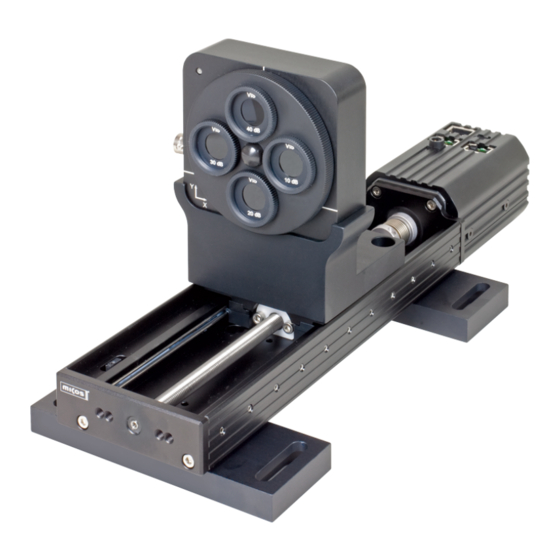
Setting up 3.5.5.1 Mechanical Setup The Thorlabs BC1M2 Extension set for M measurements is not a compact instrument but consists of separate components which are built together. In addition, means for beam alignment and focusing need to be ordered separately. - Page 96 Thorlabs Beam 4.0 Now insert both dowel bolts into the mounting plate of the translation stage. Put the adapter plate with the Beam Profiler mounted on it onto the mounting plate of the translation stage so that the two dowel bolts guarantee a nearly free from play connection.
-
Page 97: Electrical Connections
The M² translation stage controller interfaces with the control PC via a COM port (serial RS232 interface). The connecting cable has a RJ45 connector on the translation stage's end and a 9pin female DSUB connector on the other end. © 2011 Thorlabs... - Page 98 Thorlabs Beam 4.0 If your computer does not have available a COM port, please use the supplied with the M² meter package USB to Serial converter. The driver for this converter is installed automatically to your system with the software installation, so upon first...
- Page 99 Operating the Beam Profiler Unplug the USB converter and connect it again - now it works as intended. © 2011 Thorlabs...
-
Page 100: M² Measurement
M² measurements. Measurement allows to measure beam quality of a focussed beam. If the beam is unfocussed (diverging or converging without a beam waist), Thorlabs Beam software offers the Divergence measurement feature: 3.5.6.1... - Page 101 Be sure to have the translation stage with the Beam Profiler on it mounted in a way that prevents any contact to ambient mechanical parts while driving over the entire stage length! Otherwise lasers, lenses, holders or other mechanics may be damaged! © 2011 Thorlabs...
-
Page 102: Beam Alignment
Thorlabs Beam 4.0 3.5.6.2 Beam Alignment Why Beam Alignment? The Beam Profiler has a defined input aperture, so when moving it along the translation stage's axis it must be ensured that the laser beam remains within the aperture. Ideally, the beam centroid remains centered within the aperture during movement of the beam profiler. - Page 103 They can be "zeroed" (reset): Mechanical Setup For the mechanical setup at least two mirrors are required to allow positioning the laser beam in any direction. The following picture gives an idea of a possible setup. © 2011 Thorlabs...
- Page 104 Thorlabs Beam 4.0 Note When mounting the mirrors ensure to keep some space between the second mirror and the translation stage. Mind that you might like to add a lens and/or an iris diaphragm. Doing The Beam Alignment If the laser beam is already led over the two mirrors to the beam profiler a convinient way to align the laser beam is described in the following.
- Page 105 When the BC106 is located close to the beam waist, select the correct ND filter from the filter wheel in order to avoid saturation. When the beam is still centered at all stage position the lens is well-aligned into the optical path. © 2011 Thorlabs...
-
Page 106: M² Panel
Thorlabs Beam 4.0 3.5.6.3 M² Panel This section concerns the M measurement and its settings. Click to in the Beam Quality Measurement window to enter the M Measurement section. Via Menu "View" -> M² Workspace" can be accessed a convenient display, consisting of the Beam Quality Measurement... - Page 107 In the diagram (which is of course empty at the beginning) the measured data are plotted. The Position Bar at the bottom shows the actual position of the translation stage as seen before in the Initialize tab. © 2011 Thorlabs...
- Page 108 Thorlabs Beam 4.0 On the right side of the diagram the Calculation To Actual Z Position and the Results of the M measurement are displayed; the boxes are empty so far no measurement has been made yet. The panel Calculation to Actual Z Position contains the following information:...
-
Page 109: M² Settings
3.5.6.4 M² Settings For a successful and reliable measurement it is essential to adapt the measurement settings. Click on to enter the M Measurement Settings dialog. © 2011 Thorlabs... - Page 110 Thorlabs Beam 4.0 Beam Width The calculation of the 4 Diameter follows the ISO 11146-1:2005 standards. According to ISO11146-1, if the ellipticity is larger than 0.87, the beam profile may be considered to be of circular symmetry at the measuring location - in this case a 4 simplified calculation can apply.
- Page 111 The software provides two different kinds of scan methods, the Normal Scan and the Coarse Scan. The Coarse Scan just takes the sleigh of the translation stage from Start to Stop (or vice versa depending on the position of the sleigh before starting the © 2011 Thorlabs...
- Page 112 Thorlabs Beam 4.0 measurement). The number of recorded beam widths equates exactly to entered number of Data Points. The Normal Scan is in the first instance equal to the Coarse Scan but can add a series of further data points if some conditions for an ISO compliant measurement are not yet given.
-
Page 113: Running The Measurement
- depending on the source this might last up to 1 hour. the laser output is spatially and temporally stable. Start the measurement by clicking on the Start button While running the measurement most of the buttons and options are disabled, e.g. © 2011 Thorlabs... -
Page 114: Numerical Results
Thorlabs Beam 4.0 the M² measurement settings and the toolbar. This prevents the modification of settings during a measurement. If necessary, the measurement can interrupted by clicking the Stop button After starting the measurement the X axis of the diagram is adapted to the user- defined scan range, for example from 0 to 120 mm. - Page 115 X and Y. Furthermore the M² value for X' is independently from the one of Y'. For highly elliptical beams like from semiconductor lasers M X' and M Y' differ much more as in this example. These values can also be found in the listing of the complete Results. © 2011 Thorlabs...
- Page 116 Thorlabs Beam 4.0 M² Mean M² value (arithmetic average of M² X' and M² Y') M² X' and M² Y' M² value for X' or Y' axis, respectively, calculated from hyperbolic fit. Beam Waist Postion X' (Y') Z position of the beam waist (smallest beam diameter). This is the calculated beam waist position in mm derived from the curve fit.
- Page 117 Therefore, move the mouse pointer over the M² curve. As soon as it hits a measurement point, it's shape changes to Then click to this point. In the Calculations to Actual Z Position panel will appear the position according to the clicked point and the calculated values. © 2011 Thorlabs...
- Page 118 Thorlabs Beam 4.0 Note Different from the Results pane, here results are calculated from the measured data without hyperbolic fit. So it may happen, that in the waist position, at the actual position are displayed diameter values less that the waist X' (Y') diameters.
-
Page 119: Troubleshooting
Clip Level of the Calculation Area. If the selected Clip Level is too high, the beam might be cut and will be measured too small. This results in a too small beam waist and a too small © 2011 Thorlabs... - Page 120 Thorlabs Beam 4.0 (even below 1). If the selected Clip Level is too small, this increases the Calculation Area, captures noise around the beam and this way the measured beam width is larger. This leads to an increased M². M² is smaller than 1.0 - How can this be? M²...
-
Page 121: Divergence Measurement
Projection window, see section 2D Projection . Both windows should be arranged that they can be observed and controlled well. Divergence tab: Same as in the M² Measurement tab you find on the left hand side a Toolbar which © 2011 Thorlabs... - Page 122 Thorlabs Beam 4.0 provide the following functionality. Button Name Function Divergence Opens the settings for the Divergence measurement Settings Play/Stop Starts / stops a Divergence measurement Grid Disables/Enables the grid in the diagram Dots/Line Toggles between a line and dots diagram for the plotted...
-
Page 123: Divergence Measurement Settings
This angle is then used to evaluate all following frames and ellipses. Measurement Parameters Timeout is the max. waiting time for a valid camera image. This is to allow the Autoexposure function to obtain a valid camera image Wavelength is not relevant for divergence measurement. © 2011 Thorlabs... - Page 124 Thorlabs Beam 4.0 Scan Range The Scan Range determines the range from where to where sleigh of the translation stage is driven during a measurement. Start has to be at least 5 mm smaller than Stop and greater-than-or-equal to 0 mm. Valid values for Stop are 5 mm <...
-
Page 125: Running The Measurement
0 to 120 mm. The Y axis scales automatically to the recorded beam widths. 3.5.7.4 Numerical Results If a divergence measurement was successful the Beam Quality Measurement window looks like the one below. © 2011 Thorlabs... - Page 126 Thorlabs Beam 4.0 The green bulb indicates that the measurement was successful. In general the axes X' and Y' do not coincides with the lab system which is described by the axes X and Y. Furthermore the divergence angle for X' is independent from the one of Y'.
- Page 127 Save measurement data as ASCII file (*.txt) or as EXCEL spreadsheet (*.xls). Save measurement data as *.pdf file. Zooming and panning the display Both axes in M² measurement result display can be zoomed and also panned, see M² Measurement results © 2011 Thorlabs...
-
Page 128: Part Iv Computer Interface
Thorlabs Beam 4.0 Computer Interface Thorlabs Beam software is a 32 bit Windows ® application capable to recognize, initialize and control scanning slit and camera beam profiler instruments. This software was created in Visual Studio 2008 and uses QT libraries. - Page 129 When terminate your own application, devices must be released: deviceClass->releaseDevice(); 2. Thorlabs Beam Library application Thorlabs Beam Library is a library handling the device modules and providing simple functions for device access. Prior to all, a library instance must be created. Device modules are searched and loaded: CreateThorlabsBeamInstance();...
-
Page 130: Sample Programs
(e.g. LabVIEW ® ). 3. LabVIEW ® application For LabVIEW ® programming VIs (converted from Thorlabs Beam Library functions) are supplied. These VIs allow to use all Thorlabs Beam Library functions. Sample Programs C++ program sample with MFC Sample program „ThorlabsBeamSamplec++MFC“ is a standard MFC application with inserted Thorlabs Beam library functions. - Page 131 In PaintEvent a new result is requested: CALCULATION_CLUSTER calcCluster; unsigned char* imageData = NULL; width; height; lStride; if(0 == GetMeasurement(&calcCluster, &imageData, &width, &height, &lStride)) […] When terminate the program, devices and their drivers are being released: ReleaseThorlabsBeamInstance(); © 2011 Thorlabs...
- Page 132 Thorlabs Beam 4.0 LabVIEW ® program sample Here, the Thorlabs Beam library functions are used via VIs. These VIs are located in the „ThorlabsBeamLibrary.lvlib“ library. Description of „ThorlabsBeamLabViewSample.vi“: - at program start, the Thorabs Beam Library is initialized - the number of connected devices is displayed in the „Connected Devices“ box - the index entered to „Device ID“...
-
Page 133: Thorlabs Beam Library
Computer Interface Thorlabs Beam Library Function description of the Thorlabs Beam Library can be found in the file „ ThorlabsBeamLibrary.h“: © 2011 Thorlabs... -
Page 134: Part V Maintenance And Repair
Thorlabs. Do not remove covers! Version and other Information The menu entry Help About Thorlabs displays application relevant data. In case of a support request, please submit the software version of the application. This will help to locate the error. -
Page 135: Cleaning
Removing dust from the naked sensor chip can only be done using compressed gas which is free from oil and water. Thorlabs duster spray (Tetrafluoroetane) can be recommended. Keep the gas nozzle at least at a distance of 4 inches (10 cm) from... - Page 136 Keep a distance of minimum 4 inches (10 cm) when cleaning using compressed gas. In case a professional cleaning of the windowless CCD sensor is required, please return the instrument to Thorlabs, see the appropriate Addresses ND Filters ND filters (see...
-
Page 137: Troubleshooting
Connect a BC106 Beam Profiler to the PC and wait a few seconds until its LED lights up green. Click 'Refresh Device List' within the Device Selection panel. Select the instrument and click 'Close' See chapter Start the Application for a detailed description. © 2011 Thorlabs... - Page 138 Thorlabs Beam 4.0 Erroneous or no measurement results Uncover the camera's filter caps. Direct the beam to be measured to the Beam Profiler aperture. Check it's power level is within the measurable Power Range Check Exposure Time and Gain settings. Choose 'Auto Exposure Control' in Device Settings.
-
Page 139: Part Vi Application Note
In the following sections detailed explanations are given to the measured parameters. Ambient Light Correction Thorlabs Beam software implements a unique Ambient Light Correction (ALC) method. You may have noticed, that the correction process takes a certain time, shown on the... -
Page 140: Raw Data Measurements
Thorlabs Beam 4.0 Raw Data Measurements Beam Width (4 ) Width on X and Y axes (centroids), based on the second moment calculation centroid Intensity centroid Intensity Beam width (4 ) can be calculated also based using radial distance (pixel - centroid;... - Page 141 Area of an ideal flat top beam with same peak intensity: SumAllPixe PixelArea ef f PeakIntens For calculation into mm² , PixelArea is equal to 6,45*6,45 µm² Peak Density Power on peak pixel divided by its area © 2011 Thorlabs...
-
Page 142: Ellipse (Fitted)
Thorlabs Beam 4.0 Ellipse (fitted) The beam shape is being fitted to an ellipse using the set clip level (down from the peak). Diameter (clip level) is given for the minor axis (min), major axis (max) and their arithmetic mean value. -
Page 143: Gaussian Fit Measurement
Profiles. Gaussian Intensity is the correlation between the beam profiles in a line (X) and column (Y) and its appropriate Gaussian curve fit Gaussian Diameter is the width of the Gaussian fit at the 1/e² intensity level © 2011 Thorlabs... -
Page 144: Theory
Thorlabs Beam 4.0 M² Theory The diameter d(z) of a focused laser beam of fundamental modeTEM increases with distance z from its waist position. with waist diameter Rayleigh length wavelength This formula is simplified. If the waist position z is not zero, z has to be replaced... - Page 145 Gaussian beam is preferred to use because of its minimum divergence angle and the ability to get the minimal focus diameter. Differences to Gaussian shape can be due to existence of higher modes amplitude and phase distortions due to inhomogeneous gain medium in lasers occurrence of extraordinary beams © 2011 Thorlabs...
- Page 146 Thorlabs Beam 4.0 These distortions lead to higher divergence and wider beam waist compared to Gaussian beams when focused using the same lens. As a result the achievable max. power density is reduced. Comparison of propagation between fundamental mode TEM...
-
Page 147: Focal And Stage Length Calculation
Rayleigh length for a non-gaussian beam with fixed divergence angle highest expected M value operating wavelength beam waist diameter Refer to diagram B for quick selection help. Besides this minimum requirement, more flexibility is added to the setup by selecting a longer stage. © 2011 Thorlabs... -
Page 148: Part Vii Appendix
Thorlabs Beam 4.0 Appendix Certifications and Compliances The Thorlabs GmbH, Hans-Böckler-Strasse 6, D-85221 Dachau, declares under it's own responsibility, that the products Camera Beam Profiler BC106-UV, BC106-VIS fulfill the requirements of the following standards and therefore corresponds to the regulations of the directive. -
Page 149: Warranty
GmbH does explicitly not warrant the usability or the economical use for certain cases of application. Thorlabs GmbH reserves the right to change this instruction manual or the technical data of the described unit at any time. © 2011 Thorlabs... -
Page 150: Copyright
User Manual. Should you require further information on this product, or encounter specific problems that are not discussed in sufficient detail in the User Manual, please contact your local Thorlabs dealer or system installer. -
Page 151: Technical Data
16.7 mm (6.65") Surface Compatible Light cw, pulsed Sources 1 Hz - 50 kHz (single pulse exposure), Pulse Frequency unlimited (multi pulse exposure) TTL level , BNC jack 5) Trigger Input Trigger Delay 42 µs - 1 s, programmable © 2011 Thorlabs... - Page 152 Thorlabs Beam 4.0 Model BC106-UV BC106-VIS Physical Size (H x W x 80 x 80 x 36.5 mm including base plate, filter wheel and filters Weight 310 g Mounting UNC1/4-20 and M6 on base plate PC Interface High speed USB2.0 Power Supply 2.4 W, USB bus powered...
-
Page 153: Wavelength Response
1. Wavelength Dependent Sensitivity of BC106 Models Image sensors of both BC106 models show a wavelength depending response. The following diagrams show its relative response. Whereas model BC106-VIS offers about double sensitive in the visible wavelength range, it suffers from nearly zero sensitivity in the UV range below 300 nm. - Page 154 2. Wavelength Dependent Loss of VIS ND Filters The following diagram shows the measured wavelength dependent loss of all four ND filters supplied with the BC106-VIS Camera Beam Profiler. As seen, the ND filters keep their nominal loss values only coarsely within a limited wavelength range in the visible.
- Page 155 AR coating is important for a good image quality. The displayed curve shows the remaining reflectivity of the AR coating supplied on the fused silica substrate. Between 220 nm and 340 nm is below 0.25 %. © 2011 Thorlabs...
-
Page 156: Accessories
The following accessory list may help mounting the instrument, increase the usable Power Ranges and appoint suggested cleaning tools. This equipment does not belong to the BC106 scope of delivery but is available from the Thorlabs website http://www.thorlabs.com. Part Thorlabs item... -
Page 157: Drawings
Appendix 7.4.4 Drawings 7.4.4.1 BC106-UV © 2011 Thorlabs... -
Page 158: Bc106-Vis
Thorlabs Beam 4.0 7.4.4.2 BC106-VIS © 2011 Thorlabs... -
Page 159: Bc1M2 Mounting Adapter
Appendix BC1M2 Mounting Adapter 7.4.4.3 © 2011 Thorlabs... -
Page 160: Translation Stage
Thorlabs Beam 4.0 7.4.4.4 Translation Stage VT-80 © 2011 Thorlabs... -
Page 161: Thorlabs "End Of Life" Policy (Weee)
Waste Treatment on your own Responsibility If you do not return an "end of life" unit to Thorlabs, you must hand it to a company specialized in waste recovery. Do not dispose of the unit in a litter bin or at a public waste disposal site. -
Page 162: Listings
Thorlabs Beam 4.0 Listings 7.6.1 List of Acronyms The following acronyms and abbreviations are used in this manual: 2 Dimensional 3 Dimensional ADC Analog to Digital Converter Anti Reflection Beam Profiler Camera Calculation Area Continuous Wave (constant power source) Graphical User Interface... -
Page 163: Thorlabs Worldwide Contacts
Appendix 7.6.3 Thorlabs Worldwide Contacts USA, Canada, and South America Thorlabs, Inc. 435 Route 206 Newton, NJ 07860 Tel: 973-579-7227 Fax: 973-300-3600 www.thorlabs.com www.thorlabs.us (West Coast) Email: sales@thorlabs.com Support: techsupport@thorlabs.com Europe UK and Ireland Thorlabs GmbH Thorlabs Ltd. Hans-Böckler-Str. 6... -
Page 164: Index
Thorlabs Beam 4.0 BNC Jack Index BP1M2 - C - C++ example - µ - C++ Libraries (*.dll) µm Calculation Area 33, 59 - 1 - Calculation Conditions Calculation Results 59, 69 12 bit Calculation Results Window - 2 -... - Page 165 List of Acronyms Power too high - M - Power too low Precision Mode M2 Application Notes Preparation M2 Display Preview Image 49, 50 M2 Measurement 98, 111 Program Start M2 Setup Pulsed Laser Sources M2 Workspace Main Window © 2011 Thorlabs...
- Page 166 Thorlabs Beam 4.0 USB Driver Installation - R - USB to Serial converter 95, 98 Rayleigh length 87, 142, 145 User Filter Reference Position User Power Correction Region of Interest 49, 50 - V - Repetition Frequency Repetitive Pulses Version and other Informations...
Need help?
Do you have a question about the BC106-VIS and is the answer not in the manual?
Questions and answers