Advertisement
Quick Links
Parts
INSTRUCTIONS-PARTS LIST
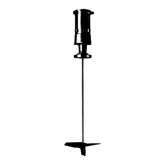
Low Shear Agitators
LSA 200, LSA 220, LSA 300
The Graco LSA series, low-shear agitators are de-
signed to reduce energy consumption and decrease
material degradation. Electric, air, and hydraulic mo-
tors are available, as are various shaft lengths and im-
peller sizes.
LSA 200 - 5.04:1 ratio gear reducer, and a standard
maximum shaft output of 350 RPM with 1750 RPM
shaft input. Choice of the air-powered (variable speed)
or the electric motor.
LSA 200H - (hydraulic) direct drive, with 0 - 350 RPM
shaft output using the 0.25 HP motor.
LSA 220 - 6.32:1 ratio gear reducer, and a standard
maximum shaft output of 280 RPM with 1750 RPM
shaft input. Choice of the air-powered (variable speed)
or the electric motor.
LSA 220H - (hydraulic) direct drive, developing 0 to
280 RPM shaft output using the 0.25 HP motor.
LSA 300 - 6.32:1 ratio gear reducer, and a standard
maximum shaft output of 140 RPM with 900 RPM
shaft input. Choice of the air-powered (variable speed)
or the electric motor.
LSA 300H - (hydraulic) direct drive, with 0 - 140 RPM
shaft output using the 0.25 HP motor.
Table of Contents
. . . . . . . . . . . . . . . . . . . . . . . . . . . . . . . . . . . . . .
. . . . . . . . . . . . . . . . . . . . . . . . . . . . . . . . . . . . .
. . . . . . . . . . . . . . . . . . . . . . . . . . . . . . . . . . . . .
. . . . . . . . . . . . . . . . . . . . . . . . . . . . . . . . . . . . . .
. . . . . . . . . . . . . . . . . . . . . . . . . . . . . . . . . . . . . . . .
. . . . . . . . . . . . . . . . . . . . . . . . . . . . . . . . . . . . .
This manual contains important
warnings and information.
READ AND RETAIN FOR REFERENCE
. . . . . . . . . . . . . . . . . . . . . . . . . . . . . . . . . .
. . . . . . . . . . . . . . . . . . . . . . . . . . . . . . . .
GRACO INC. P.O. BOX 1441
Graco Inc. is registered to I.S. EN ISO 9001
2
4
9
10
11
16
27
28
MINNEAPOLIS, MN 55440-1441
ECOPYRIGHT 2000, GRACO INC.
310500
Rev. D
Advertisement

Subscribe to Our Youtube Channel
Related Manuals for Graco LSA 200


Summary of Contents for Graco LSA 200
-
Page 1: Table Of Contents
Electric, air, and hydraulic mo- tors are available, as are various shaft lengths and im- peller sizes. LSA 200 – 5.04:1 ratio gear reducer, and a standard maximum shaft output of 350 RPM with 1750 RPM shaft input. Choice of the air-powered (variable speed) or the electric motor. -
Page 2: Warnings
WARNING WARNING FOR PROFESSIONAL USE ONLY. OBSERVE ALL WARNINGS. Read and understand all instruction manuals before operating equipment. FIRE, EXPLOSION, AND ELECTROSTATIC SHOCK HAZARD Improper grounding, poor air ventilation, open flames or sparks can cause a hazardous condition and result in fire or explosion and serious injury. D Ground the equipment and the object being sprayed. - Page 3 D This equipment is for professional use only. D Read all instruction manuals, tags, and labels before operating the equipment. D Use the equipment only for its intended purpose. If you are uncertain about the usage, call Graco Technical Assistance at (313) 416–3400.
-
Page 4: Installation
NOTE: If installing more than one impeller onto the For best results, do not remove any protective wrap- pings from any of the agitator parts until just prior to shaft, call Graco technical assistance for spacing assembly and installation. Also, store the agitator recommendations. - Page 5 Installation Shaft Installation WARNING 1. Check the access hole in the drive unit housing to MOVING PARTS HAZARD see if the drive quill set screw (58) is accessible Moving equipment parts can cause (see Fig. 2). injury, including amputating of hands or fingers.
- Page 6 Fig. 3 Electric Agitators 2. Check the stator winding insulation resistance. If the resistance is less than 1 megohm, call Graco Refer to the motor wiring diagram (Fig. 3). Customer Service for assistance. The required power supply varies depending on your 3.
- Page 7 HYDRAULIC SUPPLY LINE When connecting the air power (see Fig. 5): HYDRAULIC RETURN LINE 1. Install an air line filter (5 micron, Graco part no. 515873, or equivalent) to remove harmful dirt and moisture from the air supply. 10 MICRON...
-
Page 8: Operation
Installation Grounding the Agitator Ground The System Fluid dispensing can cause a static charge to build, To reduce the risk of static sparking, ground the valve which can spark, and cause electrical shock, or explo- and all other dispensing equipment used or located in sions. - Page 9 Operation Operation – Electric Motor Operation – Hydraulic Motor The agitator speed is fixed for electric motor models; The agitator speed for hydraulic motor models is the specific speed depends on the model type. See variable over a certain range, depending on the model Technical Data on page 27 for electrical requirements type.
-
Page 10: Maintenance
Maintenance WARNING CAUTION MOVING PARTS HAZARD Use only Mobil Mobilith SHC 007 lubricant to Moving parts, such as an impeller blade, lubricate the gear housing. The use of any other can pinch or amputate fingers. To may cause part deterioration or inadequate reduce risk of injury or damage to equip- performance. -
Page 11: Service
Service 5. Remove the agitator from the tank: WARNING a. Make sure any lifting device used is of MOVING PARTS HAZARD adequate capacity for the agitator. Moving parts, such as an impeller blade, can pinch or amputate fingers. To b. Loosen and remove the nuts and washers reduce risk of injury or damage to equip- securing the agitator to the mounting surface. - Page 12 Service Air or Electric Motor Removal SUN GEAR (9) NOTE: Agitators with hydraulic motors are direct DRIVE drive, and do have not reducers. See Hydraulic 3.27–3.28” COUPLER Motor Removal and Replacement . (83–83.3mm) (102) 1/16” min. 1. Make sure power is disconnected from the unit (see Power Connection ).
- Page 13 Service Gear Reducer / Bearing Assembly Gear Carrier Lubrication Replacement All agitator bearings are sealed and pre-packed with lubricant. Lubrication of these bearings is not neces- This procedure assumes the motor has been sary. removed (see Air or Electric Motor Removal , page 12).
- Page 14 Service Air or Electric Motor Replacement This procedure assumes the motor has already been removed, and the gear reducer and bearing housing have been replaced, if necessary (see pages 12–13 for procedures). Refer to Fig. 9 for this procedure. 1. Verify the elevation of the sun gear (9) and coupler (102) on the motor shaft to be as shown in Fig.
- Page 15 Service Hydraulic Motor Replacement This completes the motor replacement. To reinstall the agitator, refer to the Installation instructions. 1. Make sure power is disconnected from the unit (see Power Connection ). WARNING PRESSURIZED FLUID HAZARD To reduce the risk of serious injury, such as fluid injection or splashing fluid in the eyes or on the skin, follow the Hydraulic Pressure Relief Procedure on page 9.
-
Page 16: Parts
Parts LSA 200, LSA 220, LSA 300 Part No. Description 51A023 Gear carrier assembly (LSA 200 only) 1 51A024 Gear carrier assembly (LSA 220, 300) 1 51A027 Gear housing 51A025 O-ring 51A026 O-ring 51A021 Quill shaft – 16mm (LSA 200, 220) 51A022 Quill shaft –... - Page 17 (LSA 300 only) 51A045 Lock washer 51A046 Flange 51A972 Socket flat head screw 3.18 mm 0.125 in Seal retainer plate (LSA 200,220 only) 1 51A974 Seal retainer plate (LSA 300 only) 51A975 57.2 mm 51A971 O-ring 2.27 in 101a 51A976...
- Page 18 Parts LSA-200 AGITATOR LSA Drive Units Part No. Form No. 516552* 305633 Electric 516556 305633 Hydraulic 516560 305633 * Requires 96A498 Filter Kit (5 micron) 51B373 Filter Element (5 micron) NOTE: LSA–200 Agitator shaft diameter is 16 mm. Agitator Agitator Shaft Shaft Shaft Length...
- Page 19 Parts LSA-200 AGITATOR (continued) Shaft Impeller Shaft Impeller Length Diameter Length Diameter Agitator Drive Agitator Drive in. (mm) in. (mm) in. (mm) in. (mm) Part No. Type Part No. Type 922000 Electric 29 (737) 7.6 (193) 922022 Electric 33 (838) 7.6 (193) 922198 Electric...
- Page 20 Parts LSA-220 AGITATOR LSA Drive Units Part No. Form No. 516553* 305519 Electric 516557 305519 Hydraulic 516561 305519 * Requires 96A498 Filter Kit (5 micron) 51B373 Filter Element (5 micron) NOTE: LSA–220 Agitator shaft diameter is 16 mm. Agitator Agitator Shaft Shaft Shaft Length...
- Page 21 Parts LSA-220 AGITATOR (continued) Shaft Impeller Shaft Impeller Length Diameter Length Diameter Agitator Drive Agitator Drive in. (mm) in. (mm) in. (mm) in. (mm) Part No. Type Part No. Type 922036 Electric 29 (737) 10.0 (254) 922231 Electric 32 (813) 10.0 (254) 922037 Electric...
- Page 22 Parts LSA-220 AGITATOR (continued) Shaft Impeller Shaft Impeller Length Diameter Length Diameter Agitator Drive Agitator Drive in. (mm) in. (mm) in. (mm) in. (mm) Part No. Type Part No. Type 962841 Electric 35 (889) 10.0 (254) 922253 Electric 36 (914) 10.0 (254) 922249 Electric...
- Page 23 Parts LSA-300 AGITATOR LSA Drive Units Part No. Form No. 516554* 305520 Electric 516558 305520 Hydraulic 516562 305520 * Requires 96A498 Filter Kit (5 micron) 51B373 Filter Element (5 micron) NOTE: LSA–3000 Agitator shaft diameter is 20 mm. Agitator Agitator Shaft Shaft Shaft Length...
- Page 24 Parts LSA-300 AGITATOR (continued) Shaft Impeller Shaft Impeller Length Diameter Length Diameter Agitator Drive Agitator Drive in. (mm) in. (mm) in. (mm) in. (mm) Part No. Type Part No. Type 922080 Electric 34 (864) 15.1 (384) 922107 Electric 37 (940) 15.1 (384) 922081 Electric...
- Page 25 Parts LSA-300 AGITATOR (continued) Shaft Impeller Shaft Impeller Length Diameter Length Diameter Agitator Drive Agitator Drive in. (mm) in. (mm) in. (mm) in. (mm) Part No. Type Part No. Type 922135 Electric 40 (1016) 15.1 (384) 962795 Electric 43 (1092) 15.1 (384) 922136 Electric...
- Page 26 Multiply by RPM to obtain gallons per minute flow capacity Accessories Part No. Description 618776 Adapter plate (LSA 117 to LSA 200/220) 962802 Adapter plate (LSA 80 to LSA 200/220) 516315 Gortex gasket (ID 2.5”, OD 7.5” x 0.06”) 310500...
-
Page 27: Technical Data
Working Type Ratio Input Consumption Pressure Electric 1750 5.04:1 230/460 .8 @ 460 /1.5 @ 230 ––– LSA 200 LSA 200 0-1750 5.04:1 0-350 ––– 15 scfm (6.5 bar) @ 90 psi 90 psi LSA 200H Hydraulic 0-350 ––– 0-350 –––... -
Page 28: Warranty
Graco distributor to the original purchaser for use. With the exception of any special, extended, or limited warranty published by Graco, Graco will, for a period of twelve months from the date of sale, repair or replace any part of the equipment determined by Graco to be defective.
Need help?
Do you have a question about the LSA 200 and is the answer not in the manual?
Questions and answers