Table of Contents
Advertisement
Operation, Repair and Parts
EcoQuip 2
Vapor Abrasive Blast System
Vapor abrasive blast system for coating removal and surface preparation.
For professional use only.
See page 2 for model information and approvals.
Maximum Working Pressure: 150 psi (
Important Safety Instructions
Read all warnings and instructions in this and all
related manuals. Save these instructions.
™
EQp
1.03 MPa, 10.3 bar)
3A4802D
EN
Advertisement
Table of Contents

Subscribe to Our Youtube Channel
Related Manuals for Graco EcoQuip 2 EQp


Summary of Contents for Graco EcoQuip 2 EQp
- Page 1 Operation, Repair and Parts ™ EcoQuip 2 3A4802D Vapor Abrasive Blast System Vapor abrasive blast system for coating removal and surface preparation. For professional use only. See page 2 for model information and approvals. Maximum Working Pressure: 150 psi ( 1.03 MPa, 10.3 bar) Important Safety Instructions Read all warnings and instructions in this and all...
-
Page 2: Table Of Contents
Repair ........28 Graco Standard Warranty ....46 Pinch Hose Inspection . -
Page 3: Warnings
Warnings Warnings The following warnings are for the setup, use, grounding, maintenance, and repair of this equipment. The exclama- tion point symbol alerts you to a general warning and the hazard symbols refer to procedure-specific risks. When these symbols appear in the body of this manual or on warning labels, refer back to these Warnings. Product-specific hazard symbols and warnings not covered in this section may appear throughout the body of this manual where applicable. - Page 4 Warnings WARNING EQUIPMENT MISUSE HAZARD Misuse can cause death or serious injury. • Do not operate the unit when fatigued or under the influence of drugs or alcohol. • Do not exceed the maximum working pressure or temperature rating of the lowest rated system component.
- Page 5 Warnings WARNING MOVING PARTS HAZARD Moving parts can pinch, cut or amputate fingers and other body parts. • Keep clear of moving parts. • Do not operate equipment with protective guards or covers removed. • Pressurized equipment can start without warning. Before checking, moving, or servicing equip- ment, follow the Pressure Relief Procedure and disconnect all power sources.
-
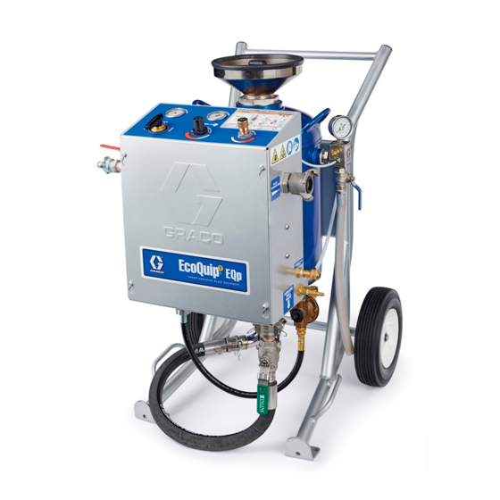
Page 6: Component Identification
Component Identification Component Identification System Component Identification System Component Identification Key Ref. Description Ref. Description Air Supply Connection Frame Blast Hose Connection Blast Control Switch Pneumatic Control Connection Blast Nozzle Supply Pressure Gauge Blast Hose Abrasive Material Pot Outlet Manifold Pop-up Handle Ground Wire and clamp Siphon Hose... -
Page 7: Pressure Relief Procedure
4. Disconnect the air supply hose. (237686). 5. Turn the selector valve (W) to BLAST. Air and fluid hoses: Use only genuine Graco blast hoses with a maximum of 150 ft (45 m) combined blast hose length to ensure grounding continuity. Check the electrical resistance of the blast hoses. -
Page 8: Operation
Operation Operation Lifting the System Blasting on Higher Surfaces • Lift the system with a lift apparatus rated appropri- NOTICE ately for the weight of the system (see Technical When blasting on a surface higher than the equipment, Specifications, page 45). make sure that there is a length of blast hose on the ground equal to 10-20% of the height. -
Page 9: Connecting The Water Supply
Operation Connecting the Water Supply Non-Pressurized Water Supply NOTE: The fill/flush valve will not operate with a non-pressurized water supply. NOTICE NOTE: To prime the pump, turn the selector valve to BLAST. Pump runaway can damage pump seals. If the pump begins to run too fast, shut it down to avoid damage. -
Page 10: Connecting The Blast Hose And Air Hose
Operation Connecting the Blast Hose and 3. Connect an appropriately sized air supply hose to the air inlet and install the hose restraints and cou- Air Hose pler pins (see Technical Specifications, page 45). 1. Connect the grounding cable clamp to a true earth ground. - Page 11 Operation 4. Open the compressor air supply valve (150 psi, 10.3 NOTICE Bar, 1.03 MPa) maximum. Do not use a wrench when installing the nozzle. Dam- age to the seal could occur. To avoid seal damage, NOTE: Make sure the air supply meets the appro- always hand-tighten the nozzle.
-
Page 12: Setting Up The Equipment
Operation Setting Up the Equipment 4. Open the air supply valve (Q). 1. Connect to a water supply. NOTE: If using non-pressurized water supply, turn the selector valve to BLAST to prime the pump. NOTE: The system will not work unless the air sup- ply valve is open. -
Page 13: Setting The Abrasive Metering Valve
Operation 9. Close the pot dump valve (J). 18. While blasting, set the abrasive metering valve (T) until the desired performance is achieved. 10. Open the fill/flush valve until water is above the pop-up seal, then pull up on the pop-up handle to pressurize the pot. -
Page 14: General Application Guides
Operation General Application Guides Blast Hose and Nozzle Selection Guidelines Blast Hose Reasons to Use This Hose Nozzle When to Use This Nozzle Need increased nozzle pressures with a low A compressor smaller than 185 • air flow CFM (5.24 m^3/min) is available compressor (<70 CFM (1.98 m^3/min) Increased control over the nozzle •... - Page 15 Operation Blast Pressure vs. Air Flow Chart TABLE 1: TABLE 2: 1/2 in. (12.7 mm) ID Blast Hose 1 in. (25.4 mm) ID Blast Hose Gauge Nozzle Gauge Nozzle #3 CFM #4 CFM #5 CFM #5 CFM #6 CFM #7 CFM #8 CFM Blasting Pressure Blasting Pressure...
-
Page 16: Using The Wash Feature
Operation Using the Wash Feature Turn the selector valve to WASH. The wash feature uses water (without abrasive) to rinse areas that have been blasted with abrasive. NOTICE ti30732a There will always be some residual abrasive in the blast Blast 1-2 minutes until the abrasive is cleared from the hose. -
Page 17: Refilling The Pot With Abrasive
Operation Refilling the Pot with Abrasive Shutting Down 1. Close the abrasive ball valve (M). 1. When you have finished blasting, perform wash until all of the abrasive is flushed from the blast hose (see Using the Wash Feature, page 16). 2. -
Page 18: Draining The Pot
Operation Draining the Pot 5. Close the abrasive ball valve (M). With Pressurized Water Supply: 1. Turn the selector valve to OFF. 6. Disconnect the abrasive ball valve cam-lock by removing the coupler pins and pulling the rings out and up to pull the two cams away from the groove. ti30725a 2. - Page 19 Operation 8. Place a bucket under the abrasive hose. Slowly 10. Open the abrasive ball valve and drain the pot of open the abrasive ball valve to flush abrasive mate- water. rial from the pot. 11. Connect the abrasive hose. NOTE: Once the water surges from the abrasive hose, close the ball valve and pull up on the pop-up NOTE: The system must be winterized if it will be...
- Page 20 Operation With Non-Pressurized Water Supply: 5. Turn the selector valve to BLAST and when water is above the pop-up seal, pull up on the pop-up handle 1. Open the abrasive ball valve (M). to pressurize the pot. NOTE: The abrasive metering valve must be open for water to flow to the pot.
-
Page 21: Winterizing The Equipment
Operation Winterizing the Equipment 6. Open the air supply valve. 7. Turn the selector valve to BLAST with the abrasive metering valve 1/4 turn open until the blast water tubing is full of windshield wash. NOTICE Vapor abrasive blasters must be winterized whenever there is a possibility of freezing temperatures during stor- age to avoid damage to the equipment. -
Page 22: Troubleshooting
Operation Troubleshooting NOTE: Always perform the Pressure Relief Procedure on page 7 before servicing or repairing any equipment. Problem Cause Solution Unable to fill or pressurize the Air supply valve is closed Open the air supply valve. pot with water The air supply is inadequate. - Page 23 Operation Problem Cause Solution Unable to fill or pressurize the The pop-up seal does not seal Make sure the pop-up is clean and free of pot with water properly. debris in the o-ring sealing area. Check for (continued) proper pop-up alignment in the closed posi- tion (there should be no gaps between the o-ring and the pop-up).
- Page 24 Operation Problem Cause Solution No blast air flow when the The air supply valve is closed. Disengage the emergency stop (Q). blast control switch (B) is The air supply is inadequate. Make sure the air compressor is capable of engaged. The water pump supplying the minimum air flow requirement does not cycle while the blast for your system (see Technical Specifica-...
- Page 25 Operation Problem Cause Solution While in BLAST mode, with The abrasive ball valve is closed. See Setting Up the Equipment on page 12. the blast control switch (B) The abrasive metering valve is not See Setting Up the Equipment on page 12. engaged, air is flowing from properly set.
- Page 26 Operation Problem Cause Solution The blast control switch (B) is The air supply is inadequate. Make sure the air compressor is capable of not engaged, but blasting supplying the minimum air flow requirement occurs. for your system (see Technical Specifica- tions on page 45).
- Page 27 Operation Problem Cause Solution The blast spray pattern is The air supply is inadequate. Make sure the air compressor is capable of sputtering or irregular. supplying the minimum air flow requirement for your system (see Technical Specifica- tions, page 45). Make sure the air inlet pres- sure gauge reads 100-150 psi (6.8–10.3 bar, 0.68–1.03 MPa).
-
Page 28: Repair
Repair Repair 6. Remove check valve components (G1, G2, G3, G4). 7. Remove the bottom hose clamp (C2). Pinch Hose Inspection 8. Pull the pinch hose (PH) out of the box. NOTE: use the blast circuit (BC) as a handle and Inspect the pinch hose monthly looking for “bubbles”... -
Page 29: Debris In Media Path
Repair Debris in Media Path 5. If visible, remove large debris and proceed to step 11. If water and media still remain in the pot and no debris is visible, proceed to step 6. 6. Remove the abrasive hose from the control box and pot at the cam-lock fittings. - Page 30 Repair 8. Probe inside the pot from the outlet until the debris is found. 9. Remove debris, inspect the gasket and replace if damaged. Reinstall the outlet manifold and torque the clamp to 15 ft-lb (19.5 N•m). NOTE: When debris is cleared, media should freely flow from the pot outlet.
-
Page 31: Notes
Notes Notes 3A4802D... -
Page 32: Parts
Parts Parts EQp Parts Torque clamp to 15 +/- 2 ft-lb after hose is connected. Apply anti-sieze to studs. 3A4802D... -
Page 33: Eqp Parts List
Parts EQp Parts List Ref. Part Description Qty. Ref. Part Description Qty. 17J329 COUPLER, cam-lock, sst, 1 nptf - - - - - PRESSURE pot, assembly, 1.5 in. cart 117559 O-RING - - - - - ENCLOSURE, EcoQuip, EQp 15E813 NUT, jam 129090 GROMMET, 9/32 in., ID, rubber, 24F148 KIT, hose, suction, 5 gal, 3/8 od black... -
Page 34: Eqp Parts (Continued)
Parts EQp Parts (continued) Apply thread sealant. Apply anti-sieze to studs. Apply grease before assembling wheels and o-ring. Torque to 70 +/- 5 ft-lb (94 +/- 6.7 N•m). EQp Parts List (continued) Ref. Part Description Qty. Ref. Part Description Qty. EQ1012 FITTING, nipple barb hose 3/4 in. -
Page 35: Enclosure Parts
Parts Enclosure Parts Apply anti-sieze to threads. 3A4802D... - Page 36 Parts Enclosure Parts List Ref. Part Description Qty. Ref. Part Description Qty. 129080 GROMMET, 1-55/64 in. id, rubber, 17R663 HOUSING, check valve, triclamp / black 1 npt 120444 SCREW, hex hd, flanged 17R854 NUT, 1-1/4 nps, sst 129561 FITTING, PTC, straight, 17R852 MANIFOLD, blast circuit, inlet 1/4 MPT, 1/4 t 129574 FITTING, PTC, union y, 1/4 t...
-
Page 37: Enclosure Parts (Continued)
Parts Enclosure Parts (continued) 3A4802D... - Page 38 Parts Enclosure Parts List (continued) Ref. Part Description Qty. Ref. Part Description Qty. - - - - - LABEL, operations - - - - - ENCLOSURE, EcoQuip 17L322 KIT, regulator, pump pressure 17H280 NUT, M20, needle valve 128672 NUT, serrated flange, #6-32, sst 17P287 BRACKET, air regulator 17K056 KIT, valve, needle 129575 FITTING, PTC, run tee, 1/4 mpt,...
-
Page 39: Kits And Accessories
Kits and Accessories Kits and Accessories Blast Hoses with Control Hose Part Blast Control Coupler 1 Coupler 2 Length Approved Nozzle holder, aluminum 2-prong coupler, 24Z140 0.5 in. aluminum 2-prong coupler, aluminum 24Z141 50 ft (15 m) Pneumatic 2-prong coupler, brass 26A077 2-prong coupler, 1.0 in. -
Page 40: Spare Parts
Kits and Accessories Spare Parts Part Description 26A093 Water tank filter with adapter (5 pack) 17R833 KIT, ball valve, 2pc, 1 in. npt 17R836 KIT, water pump, 15:1, sst 17R837 KIT, o-ring, pop-up seal 17R838 KIT, inlet funnel, pressure pot 17R839 KIT, pop-up 17R843... -
Page 41: Tubing Schematic
Tubing Schematic Tubing Schematic 14" 13" 33.5" 9" 17" 8.5" 16" 13" 15" 10" 13.5" 11.5" 7" 9" 24" 27" 3A4802D... -
Page 42: Tubing Schematic Key
Tubing Schematic Tubing Schematic Key Ref. Tubing Style Cut Length Inches (cm) Natural - 1/4 in. OD 14 in. (35.5 cm) Green - 1/4 in. OD 17 in. (43.1 cm) Green - 1/4 in. OD 9 in. (22.8 cm) Green - 1/4 in. OD 13 in. -
Page 43: Dimensions
Dimensions Dimensions 3A4802D... -
Page 44: Notes
Notes Notes 3A4802D... -
Page 45: Technical Specifications
Technical Specifications Technical Specifications EcoQuip 2 EQp Metric Maximum Air Inlet Working Pressure 150 psi 10.3 bar, 1.03 MPa Maximum Fluid Working Pressure 185 psi 12.7 bar, 1.27 MPa Operating Temperature 35° - 110° F 1.6° - 43.3° C Recommended Compressor Size 185 CFM 5.24 m^3/min... -
Page 46: Graco Standard Warranty
With the exception of any special, extended, or limited warranty published by Graco, Graco will, for a period of twelve months from the date of sale, repair or replace any part of the equipment determined by Graco to be defective.
Need help?
Do you have a question about the EcoQuip 2 EQp and is the answer not in the manual?
Questions and answers