Table of Contents
Advertisement
Quick Links
Kits - Accessories
Fluid Automation
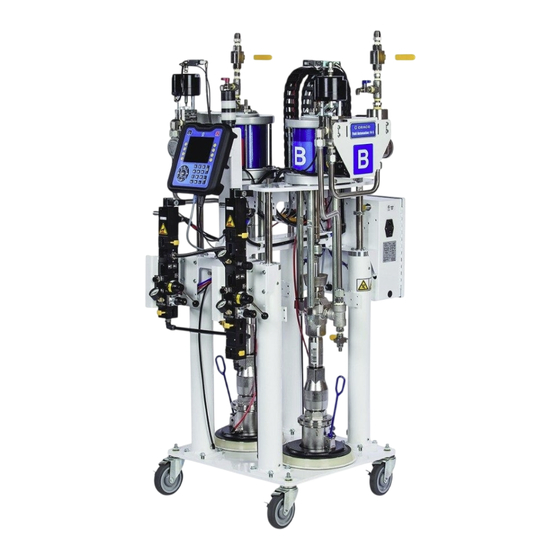
F4 Series
Kits and accessories for use with Fluid Automation F4 series systems.
For professional use only.
Not approved for use in explosive atmospheres or hazardous locations.
For use with models:
F4-5
F4-55
Refer to the Fluid Automation F4 Series Setup-Operation
manual 335028 for maximum working pressure and
model information.
Important Safety Instructions
Read all warnings and instructions in this
manual and the Fluid Automation F4 Series
Setup-Operation manual 335028. Save all
instructions.
™
3A3103A
EN
Advertisement
Table of Contents

Subscribe to Our Youtube Channel
Related Manuals for Graco Fluid Automation F4 Series


Summary of Contents for Graco Fluid Automation F4 Series
- Page 1 Kits - Accessories ™ Fluid Automation F4 Series 3A3103A Kits and accessories for use with Fluid Automation F4 series systems. For professional use only. Not approved for use in explosive atmospheres or hazardous locations. For use with models: F4-5 F4-55...
-
Page 2: Table Of Contents
Graco Standard Warranty ....46 Graco Information ......46... -
Page 3: Warnings
Warnings Warnings The following warnings are for the setup, use, grounding, maintenance, and repair of Fluid Automation F4 Series equipment. The exclamation point symbol alerts you to a general warning and the hazard symbols refer to proce- dure-specific risks. When these symbols appear in the body of this manual or on warning labels, refer back to these Warnings. - Page 4 Warnings WARNING WARNING WARNING WARNING FIRE AND EXPLOSION HAZARD Flammable fumes, such as solvent and paint fumes, in work area can ignite or explode. Paint or solvent flowing through the equipment can cause static sparking. To help prevent fire and explosion: •...
- Page 5 Warnings WARNING WARNING WARNING WARNING PRESSURIZED ALUMINUM PARTS HAZARD Use of fluids that are incompatible with aluminum in pressurized equipment can cause serious chemical reaction and equipment rupture. Failure to follow this warning can result in death, serious injury, or prop- erty damage.
-
Page 6: Installation
Installation Installation 2. Open the prime ball valves for both the A and B NOTICE pumps. ® Apply POLY-TEMP ceramic tape or equivalent to all National Pipe Threads (NPTs) when installing. Pressure Relief Procedure Prime Ball Follow the Pressure Relief Procedure Valve whenever you see this symbol. -
Page 7: F4-55 Caster Kit, 24X218
Installation F4-55 Caster Kit, 24X218 Dual Press Kit, 25A102 This kit is for attaching casters to model F4-55. 1. Lift the machine until it is at least 3 in. (8 cm) off the floor. This kit is needed when using a second press with the F4-5 and F4-55 machines. - Page 8 Installation NOTE: Apply tape to all male threads as needed. This kit includes a 3/8 in. air line tee that needs to be installed at the machine’s air line outlet port when con- 2. Attach the valve and the adapter to the dual press necting the air lines to the stacks.
-
Page 9: Second Press Cable Kit, 25A106
Connection at Stack 1. Connect the press cable to the electronic enclosure at the connection marked Press 2. 2. Refer to the Fluid Automation F4 Series Setup-Operation manual 335028 for information about connecting the cable to the press. Cable Connects Here... -
Page 10: Barrel Mixing Stacks Supported
Barrel Mixing Stack Kit, SK556 There are three models of barrel mixing stacks available for use with the Fluid Automation F4 Series. The stacks come assembled with the four 1/4 in. air line tubes and the solenoid block already attached. - Page 11 3/8 air line tee NOTE: See the Fluid Automation F4 Series Setup-Oper- included with the dual press kit (25A102) for the ation manual 335028 for information about priming the connection at the machine.
-
Page 12: Material In-Line Filters
Installation Material In-line Filters In-line Filter, SA926-1A Two in-line filter options are offered for the F4-5 and F4-55. These are installed between the barrel mixing Top of Filter stack and the press. They filter the material coming from Stack Connects Here the stack to help prevent clogging. -
Page 13: Material Regulators
Installation Material Regulators Both kits include a gauge for monitoring pressure and a ball valve for bleeding the line, if needed. The regulator has an adjustment that allows you to manually increase Material regulators help to reduce pressure fluctuations or decrease output pressure. and provide a more consistent material feed pressure into the press. -
Page 14: Colorant Tank Kits
Installation Colorant Tank Kits 2. Connect the tank to the bracket using the screw and nut provided in the kit. 3. Ensure all screws are tight to secure the tank. Colorant Tank Kit, 25A105 There are two sizes of colorant tanks available, one for the F4-5 and one for the F4-55. - Page 15 Installation 2. Attach the tank mounting bracket to the white tank 3. Connect the other end of the 1/4 in. tubing to the bracket using two socket head screws included in colorant tank air regulator on the top of the tank. the kit.
-
Page 16: Color Flow Meter Kits
NOTE: See the Fluid Automation F4 Series Setup-Oper- ation manual 335028 for information about calibrating the color flow meter and color injector. 1. Connect the flow meter to the colorant tank’s mate- Color Material rial line connection at the bottom of the tank. -
Page 17: 5-Gallon Pail Girdle, 25A160
Installation 5-Gallon Pail Girdle, 25A160 3. Connect the cable included with the kit to the stack’s solenoids at C1. This is intended for use with the F4-55 machine. The pail girdle is placed around 5-gallon pails that are used to contain material dispensed from the machine. The pail girdle reinforces the pail to help keep it from crack- ing or breaking when filling with material. -
Page 18: Continuous Low Level Sensor Kits
Installation Continuous Low Level Sensor Kits 1. Remove the hex nut from the bolt on the end of the ram beam nearest to the electronic enclosure. 2. Mount the sensor with the bracket as shown below and attach and tighten the nut until secure. The continuous low level sensors are designed to mea- sure the amount of material left in the drums and pro- vide feedback to the system. - Page 19 Installation Continuous Low Level Sensor, 25A101 This sensor kit is for the F4-5 and includes two sensors, each with a bracket for mounting to the machine and Cable and hardware for attaching the bracket. Hose Guide E Cable from Electronic Enclosure Cables from the Electronic...
-
Page 20: Parts
Parts Parts F4-55 Caster Kit, 24X218 . 1: Casters Part Description Quantity 24X217 BRACKET, caster, white 121495 CASTER, swivel, w/brake, 800 lbs 127048 SCREW, machine, hex, flange, m10 x1.5 x 25 127076 NUT, hex, flange, serrated, m10 3A3103A... -
Page 21: Dual Press Kit, 25A102
Parts Dual Press Kit, 25A102 . 2: Dual Press Part Description Quantity 123980 FITTING, swivel, 3/4 x 1/2, mf, sst, 3.5 113833 TEE, pipe, female 15428-5-SS FITTING, elbow, 90, 1/4 npt, mm, ss, 4k, 3 FAA081100 VALVE, check 3/4 npt, fxf, 4410 psi, ss 16R883 FITTING, nipple, reducing, 3/4 x 1/2 24P719... -
Page 22: Second Press Cable Kit, 25A106
Parts Second Press Cable Kit, 25A106 . 3: Second Press Cable Part Description Quantity 128197 CABLE, cga, m12, 5 pin, fxm 8, 4 pin, m 127949 HARNESS, splitter, m12 24M122 CORD, set, euro/male, din/female, rev 128441 CABLE, cga, m12, spin, m, 4m, pigtail 3A3103A... -
Page 23: Barrel Mixing Stack Kit, 24R681
Parts Barrel Mixing Stack Kit, 24R681 . 4: Stack 24R681 Part Description Quantity SA914-5A MANIFOLD, mixer, assy, gun, 1/2 npt 96/0105/99 SCREW, shc, 1/4-20 x 1.50, ms, e SK579 MANIFOLD, pneumatic, 3-solenoid, rh 4.7 ft 61/0001/88 TUBE, 1/4 in. od, poly 114373 FITTING, nipple, 1/2 npt, sst hex SM396-324... - Page 24 Parts Water Jacket and Mixer for Barrel Mixing Stack 24R681 SK513 SM396-322 412 (inside) . 5: SK513 and SM396-322 SK513 Part Description Quantity FAA040560 SCREW, shcs, 10-32 x 3.5, sst 101970 PLUG, skt hd, 1/4 npt, ss SM321003 JACKET, water, 16 cartridge SM321005 JACKET, water, 16 cartridge 94/0704-1/96...
-
Page 25: Barrel Mixing Stack Kit, 25A169
Parts Barrel Mixing Stack Kit, 25A169 . 6: Stack 25A169 Part Description Quantity SA914-5A MANIFOLD, mixer, assy, gun, 1/2 npt 114373 FITTING, nipple, 1/2 npt, sst hex SM370-24 MIXER, 2 pass, 24 elements 94/1027/98 ADAPTER, jic 12 x 1/2 npt, mm, ss, 3k, 316 4.7 ft 61/0001/88 TUBE, 1/4 in. - Page 26 Parts Water Jacket and Mixer for Barrel Mixing Stack 25A169 . 7: SM370-24 SM370-24 Parts Description Quantity 115719 PACKING, o-ring, 015,v iton FAA040231 MIXER, 0.363 x 12 el, sst 500171 SCREW, shcs, 1/4-20 x 1.75, ss 124588 SCREW, cap, sh, 1/4-20 x 1.25 lg, sst 110208 PLUG, pipe, 1/8 npt, ss 104071...
-
Page 27: Barrel Mixing Stack Kit, Sk556 And Sk556-2A
Parts Barrel Mixing Stack Kit, SK556 and SK556-2A 702A . 8: Stack SK556 Part Description Quantity SA914-3A MANIFOLD, mixer, assy, gun, 1-1/4 - 18th SK579 MANIFOLD, pneumatic, 3-solenoid, lh SM327-WJ MIXER, water, jacket, medical SM327-12 MIXER, 12 element, medical 172479 TAG, warning 4.7 ft 61/0001/88... - Page 28 Parts Mixer and Water Jacket for Barrel Mixing Stack SK556 SM327-12 SM327-WJ 812 (inside) 811 (inside) . 9: SM327-WJ and SM327-12 SM327-WJ Part Description Quantity 112781 ELBOW, swivel, 90 deg SM327-WJ KIT, housing, mixer, water, jacket 040644 RETAINER, ring, external, ss 154662 PACKING, o-ring SM327-12 - Inside SM327-WJ...
-
Page 29: Manifold/Gun Assembly For Barrel Mixer Stacks, Sa914-3A/-5A
Parts Manifold/Gun Assembly for Barrel Mixer Stacks, SA914-3A/-5A 907 (inside) . 10: SA914-3A and SA914-5A SA914-3A Part Description Quantity SG263-1A GUN, shut off, single, mat'l 080103 GAUGE, 5000 psi, liquid, 2.5 in. 16C633 FITTING, nipple, hex, 1/2 x 1/4, m x m, ss 108417 ELBOW, female, 1/4 npt, fxf, 5k, sst 080856... - Page 30 Parts Gun Parts for SA914-3A/5A 1002 1004 1007 1005 1017 1021 1013 1011 1014 1001 1012 1020 1022 1003 1019 1006 1018 1015 1008 1009 1010 . 11: SG263-1A Part Description Quantity 1001 107204† PACKING, o-ring 1002 SG263008† SEAT, carbide, .500 ball,. 999 od 1003 01161S†...
-
Page 31: Solenoid Block For Barrel Mixer Stacks, Sk579/-2A
Parts Solenoid Block for Barrel Mixer Stacks, SK579/-2A 1107 1104 1102 1106 1103 1105 1109 1109 1101 1108A 1108 . 12: SK579 and SK579-2A SK579 SK579 SK579-2A Parts Description Quantity Quantity 1101 060247 SOLENOID, pneumatic, 1/8 in., npt 1102 060255 PLATE, end, kit 1103 100721... -
Page 32: Colorant Tank Kit, 25A104
Parts Colorant Tank Kit, 25A104 1207 1205 1204 1211 1201 1209 1203 1210 1212 1202 . 13: Colorant Tank 25A104 Part Description Quantity 1201 ST802 TANK, 3-quart, feed, cs, nkl-plt 1202 16A006 FITTING, elbow, street, sst 1203 122991 ADAPTER, jic 06 x 1/4, mm, ss, 6k, 316 1204 123112 FITTING, t, 1/4 tube, prestolock, brs... - Page 33 Parts Tank Parts, ST802 1305 1302 1306 1304 1303 1310 1307 1311 1301 1312 1313 1309 1312 1308 1314 1317 1318 . 14: ST802 Parts Description Quantity 1301 00181B O-RING, buna, 254, 70 d 1302 94/0762/99 VALVE, relief, 1/4 npt, m, 115 psi, sil 1303 080003 REGULATOR, air, 0-100 psi, 1/4"...
-
Page 34: Colorant Tank Kit, 25A105
Parts Colorant Tank Kit, 25A105 1405 1407 1404 1413 1406 1401 1414 1412 1410 1411 1403 1409 1402 . 15: Colorant Tank 25A105 Part Description Quantity 1401 ST830 TANK, 3 gallon, feed 1402 16A006 FITTING, elbow, street, sst 1403 122991 ADAPTER, jic 06 x 1/4, mm, ss, 6k, 316 1404 123112... - Page 35 Parts Tank Parts, ST830 1505 1503 1502 1504 1506 1507 1510 1511 1501 1512 1513 1509 1512 1508 1514 1517 1518 . 16: ST830 Parts Description Quantity 1501 00192B O-RING, 2-265 1502 94/0762/99 VALVE, relief, 1/4 npt, m, 115 psi, sil 1503 080003 REGULATOR, air, 0-100 psi, 1/4"...
-
Page 36: Color Flow Meter Kits, 25A103 And 25A161
Parts Color Flow Meter Kits, 25A103 and 25A161 1601 1602 1603 1604 . 17: Color Flow Meter Part Description Quantity ---* METER, gear, assy, G3000HR 1601 ---** METER, gear, assy, G3000 1602 122991 ADAPTER, jic 06 x 1/4, mm, ss, 6k, 316 1603 122961 ADAPTER, swvl, jic 06 x 1/4 npt, fm, ss, 5... -
Page 37: Color Injector Kit, 25A108
Parts Color Injector Kit, 25A108 1701 1702 1703 1706 1705 . 18: Color Injector Part Description Quantity 1701 SN751-1A INJECTOR, assy, color 1702 081076 HOUSING, body, qd, 1/4 npt m, crplt, brs 1703 080071 FITTING, elbow, 90, jic 06 x 1/4 npt, mf 1705 24E899 CABLE, 5 pin, male/female, 4.0 m... - Page 38 Parts Injector Assembly, SN751-1A 1825 1833 1834 1835 1832 1830 1829 1831 1827 1801 1821 1811 1813 1819 1807 1818 1803 1845 1810 1826 1805 1812 1804 1808 1809 1806 1802 1816 1828 1824 1813 1846 1814 1823 1817 1851 1815 1850 .
- Page 39 Parts 1828 080270 POPPET, ss 1829 080503 COUPLING, qc, 1/8in. nptm x 1/8 in. flow 1830 080502 COUPLING, 1/8 in. flow x 1/4 in. od (.170 in. id) 1831 080143 FITTING, 1/8 in. nptm x 1/8 in. qc 1832 080459 HOSE, 1/8 in.
-
Page 40: 5-Gallon Pail Girdle, 25A160
Parts 5-Gallon Pail Girdle, 25A160 1902 1905 1901 1903 1904 . 20: Pail Girdle Part Description Quantity 1901 FAA040220 ROD, jig latch bolt, 3/8-16 thds 1902 FAA040518 SCREW, shc, shldr, 3/8 x 1, ss 1903 FAA040540 NUT, hex, 5/16-18, cs, gr8, u-coat 1904 KIT, pail, girdle, weldment 1905... -
Page 41: Continuous Level Sensor Kit, 25A100
Parts Continuous Level Sensor Kit, 25A100 2004 2003 2002 2001 . 21: Continuous Level Sensor 25A100 Part Description Quantity 2001 25A144 SENSOR, level, laser 2002 24W797 BRACKET, limit, 3.0 in.,5 gal. white 2003 121820 SCREW, mach, pan hd, m4 2004 124344 CABLE, gca, m12-5 p, m/f, 1.0 m 3A3103A... -
Page 42: Continuous Level Sensor Kit, 25A101
Parts Continuous Level Sensor Kit, 25A101 2106 2105 2103 2102 2104 2101 . 22: Continuous Level Sensor 25A101 Part Description Quantity 2101 25A143 SENSOR, level, laser 2102 24W797 BRACKET, limit, 3.0 in., 5 gal.white 2103 121820 SCREW, mach, pan HD, m4 2104 101535 NUT, full hex... -
Page 43: Filters And Regulators
Parts Filters and Regulators Material In-line Filter, SA925-1A 2205 2203 2208 2209 2204 2202 2201 2201 2207 2206 2210 . 23: In-Line Filter SA925-1A Part Description Quantity 2201 112245 PACKING, o-ring 2202 FAA040512 SCREEN, filter, 2.5 od, 80 mesh, sst 2203 FAA040513 SCREEN, filter, 2.5 od,100 mesh, sst... - Page 44 Parts Material In-Line Filter, SA926-1A 2305 2308 2304 2303 2302 2301 2309 2306 2307 . 24: In-Lind Filter SA926-1A Part Description Quantity 2301 103413 PACKING, o-ring 2302 040768 SCREEN, woven wire, 1 in. dia, 80 mesh 2303 040769 SCREEN, woven wire, 1in. dia, 100 mesh 2304 040770 SCREEN, woven wire, 1 in.
- Page 45 Parts Material Regulators SA920 and SA921 Part Description Quantity SA920 REGULATOR, matl, 1/2 in. npt, 600 out, sst SA921 REGULATOR, matl, 3/4 in. npt, 600 out, sst 3A3103A...
-
Page 46: Graco Standard Warranty
With the exception of any special, extended, or limited warranty published by Graco, Graco will, for a period of twelve months from the date of sale, repair or replace any part of the equipment determined by Graco to be defective.
Need help?
Do you have a question about the Fluid Automation F4 Series and is the answer not in the manual?
Questions and answers