Table of Contents
Advertisement
Quick Links
Advertisement
Table of Contents

Subscribe to Our Youtube Channel
Related Manuals for LS ELECTRIC LSLV-S100 Series


Summary of Contents for LS ELECTRIC LSLV-S100 Series
- Page 2 Before using the product Thank you for using the S100 PROFIBUS- DP module.
- Page 3 Safety Information Safety Information • Always follow safety instructions to prevent accidents and potentially hazardous situations. • Safety precautions are classified as “WARNING” and “CAUTION,” and their meanings are as follows: Indicates a potentially hazardous situation which, if not avoided, may cause death or serious injury.
-
Page 4: Table Of Contents
Table of Contents Table of Contents 1 Overview ....................... 1 What if the PROFIBUS-DP communication module is used? ...... 1 Package components ................. 1 2 LSLV-S100 PROFIBUS-DP Communication Module .......... 2 LSLV-S100 PROFIBUS-DP Communication Technical Data ...... 2 PROFIBUS- DP Communication Module Appearance ........ 5 PROFIBUS- DP Communication Connector Specifications ...... - Page 5 Table of Contents 5.1.3 Setpoint value .................... 31 5.1.4 Actual speed value ..................31 I/O Profile ....................32 LS Drive Profile ..................32 5.3.1 Control word ....................33 5.3.2 Status Word ....................33 5.3.3 Setpoint value .................... 34 5.3.4 Actual speed value ..................34 6 Communication Protocol ...................
-
Page 6: Overview
Overview 1 Overview The PROFIBUS-DP communication module allows the LSLV-S100 inverter to connect to a PROFIBUS network. This communication module does not support the IP66 product. 1.1 What if the PROFIBUS-DP communication module is used? The sequence program on the PLC or any master module can control and monitor the inverter. -
Page 7: Lslv-S100 Profibus-Dp Communication Module
LSLV-S100 PROFIBUS-DP Communication Module 2 LSLV-S100 PROFIBUS-DP Communication Module 2.1 LSLV-S100 PROFIBUS-DP Communication Technical Data Device Type PROFIBUS-DP Slave Auto Baud Rate Supported Detect Sync Mode Supported Freeze Mode Supported Max Input Length 8 words Max Output Length 8 words Baud Rate Support 9.6K, 19.2K, 45.45K, 93.75K, 187.5K, 500K, 1.5M, 3M, 6M, 12M Modular Station... - Page 8 Starting with the newly supported version 3.00, DPV0/DPV1 mode is supported, and Telegram, PNU parameters, and profiles for drive control are added. See the LS ELECTRIC homepage below for more information on ver. 2.01. www.ls-electric.com -> Download Center -> iS7 Profibus Option Manual...
- Page 9 LSLV-S100 PROFIBUS-DP Communication Module The DP versions supported by LS Profibus-DP master module are as follows: Items Description Remark XGL-PMEA Profibus-DP Master Supports DP-V0 XGK/XGI/XGR XGL-PMEC Profibus-DP Master common XGL-PMEB Profibus-DP Master Supports DP-V0 and DP-V1...
-
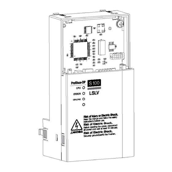
Page 10: Profibus- Dp Communication Module Appearance
LSLV-S100 PROFIBUS-DP Communication Module 2.2 PROFIBUS- DP Communication Module Appearance Figure 1 PROFIBUS-DP Communication Module... -
Page 11: Profibus- Dp Communication Connector Specifications
LSLV-S100 PROFIBUS-DP Communication Module 2.3 PROFIBUS- DP Communication Connector Specifications Figure 2 PROFIBUS Connector PROFIBUS Signal Description Connector None None 24 V Output GND RxD/TxD-P Received/Transmitted Data Plus CTRL-P Control signal for a repeater DGND Signal GND 5 V for termination resistance 24 V Output - Positive RxD/TxD-N Received/Transmitted Data - Negative... -
Page 12: Installation
LSLV-S100 PROFIBUS-DP Communication Module 2.4 Installation Turn off the inverter before configuring the communication network. Both the inverter and the communication module will be damaged if the communication module is installed or removed while the inverter is on. Install or remove the communication module after the capacitor inside the inverter is completely discharged. - Page 13 LSLV-S100 PROFIBUS-DP Communication Module Remove the screws (4) on the I/O board and fasten the enclosed brass bar (4). Fasten the communication module (5) and fasten the screw (6) removed from the I/O board and the enclosed screw (7).
- Page 14 LSLV-S100 PROFIBUS-DP Communication Module Reinstall the keypad (8) first, then reinstall the communication module covers (9) in order. Reinstall the power cover (10). The inverter is ready for use.
-
Page 15: Network Cable Specifications
LSLV-S100 PROFIBUS-DP Communication Module 2.5 Network Cable Specifications Item Description Cable Type BC-Bare Copper Insulation PE-Polyethylene Insulation Thickness 0.035 inch Aluminum Foil-Polyester, Shield Tape/Braid Shield Electrostatic Capacity 8500pF/ft Characteristic 150Ω Impedance Number of Conductors 2 Cores Table 4 Network Cable Specifications 2.6 Maximum distance depending on speed The total length of a network cable configuration varies depending on the baud rate. -
Page 16: Grounding Option
LSLV-S100 PROFIBUS-DP Communication Module * Special requirements for using transmission rate greater than 1.5 Mbps • A special connector with a built-in inductor is required to use a transmission rate of 1.5 Mbps or higher. • Spurline is not allowed when using a transmission rate greater than 1.5 Mbps. •... - Page 17 LSLV-S100 PROFIBUS-DP Communication Module Remove the communication option cover. Remove the ground mold (pull shape) of the communication option cover. Connect the ground wire using a screw to the bottom *right of the communication option. Close and assemble the communication option cover. Connect the ground (CM) of the communication option separately from the ground of the inverter.Remove the communication option cover.
-
Page 18: Operation Status And Led Indicators
Operation Status and LED Indicators 3 Operation Status and LED Indicators 3.1 Definition of LED The PROFIBUS DP communication module has 3 LED indicators. Figure 3 LED Silk Printing Color Description Flashes when the communication module is installed to the inverter Green and the power is supplied. -
Page 19: Communication Module Status Diagnosis According To Led Status
Operation Status and LED Indicators 3.2 Communication module status diagnosis according to LED status. Operation Status Cause Resolution Status Power has not been Check the power supply to provided to the the inverter. inverter or the Check if the inverter has Power PROFIBUS-DP tripped. - Page 20 Operation Status and LED Indicators Operation Status Cause Resolution Status Fault Fault from the inverter Check inverter fault history. occurred occurred. The master device has not started Start the network network communication from the communication in the master device. network. Check the pin number of the There is a problem connector for the correct...
-
Page 21: Inverter Parameters
Inverter Parameters 4 Inverter Parameters 4.1 PROFIBUS- DP communication related parameter Code Parameter Setting Default Description Number Name Range Indicates the version of the COM-06 FBus S/W Ver communication module installed to the inverter. Sets up the station ID for COM-07 FBus ID 1 ~ 125... -
Page 22: Profibus- Dp Communication-Related Parameters
Inverter Parameters Code Parameter Setting Default Description Number Name Range COM-33 Para Status-3 0x000F 0~0xFFFF COM-34 Para Status-4 0x0000 0~0xFFFF COM-35 Para Status-5 0x0000 0~0xFFFF COM-36 Para Status-6 0x0000 0~0xFFFF COM-37 Para Status-7 0x0000 0~0xFFFF COM-38 Para Status-8 0x0000 0~0xFFFF COM-50 Para Ctrl Num Set up the number of control for use. -
Page 23: Station Id Setting
Inverter Parameters 4.2.2 Station ID setting The following parameters are used to set the station ID for the PROFIBUS-DP communication module. COM-07 FBus ID COM-94 Comm Update The parameters above are used to set the Station ID for the PROFIBUS-DP communication module. -
Page 24: Number Of Para Status Settings
Inverter Parameters 4.2.4 Number of Para Status settings COM-30 Number of Para Status settings COM-31 Para Status 1–8 settings COM-38 COM-94 Comm Update The parameters above are used to determine how much Para Status data will be sent to the master device by the inverter through PROFIBUS-DP network communication. The number of the Para Status can be set to a number between 1 and 8. - Page 25 Inverter Parameters For example, if you want to set the inverter In Group's number 90 DI Status to Para Status-1, you can set it to 0x155A. 0x1000 + 0x05 x 0x100 + 0x5A(Dec 90) = 0x155A Group Group Number dr Group bA Group Ad Group Cn Group...
-
Page 26: Number Of Para Control Settings
Inverter Parameters 4.2.6 Number of Para Control settings COM-50 Number of Para Control settings COM-51 Para Control 1–8 settings COM-58 COM-94 Comm Update The parameters above are used to determine how much Para Control data will be sent to the master device by the inverter through PROFIBUS-DP network communication. -
Page 27: Comm Update
Inverter Parameters For example, if you want to set the third acceleration time of the inverter dr Group to Para Control-1, you can set it to 0x1103. 0x01 x 0x1000 + 0x01 x 0x100 + 0x03 (Dec 3) = 0x1103 Group Group Number dr Group... -
Page 28: Setting Profibus Bit Swap
Inverter Parameters 4.2.9 Setting PROFIBUS Bit Swap Set whether the LSB and MSB bit swaps of data transmitted during communication. (Set if the parent controller reads the LSB and MSB in the Profibus option data in reverse.) Set value Location on KeyPad 0 : No FBus Swap Sel 68 in COM Group... -
Page 29: Profibus Dp Profile
Inverter Parameters 4.2.11 Profibus DP Profile Displays the control operation mode for inverter operation. The parameter cannot be changed from the keypad by default, but it can be set by the keypad when using Telegram Type: 101-106 in the master. After changing to the keypad, the COM-94 com update is required to apply the corresponding values. -
Page 30: Profibus Dp Module Reset
Inverter Parameters 4.2.13 Profibus DP Module Reset Parameter for initializing the PROFIdrive parameter value of the communication option to zero. As soon as the corresponding value is set to 1, the values of p944, p947, and p953 to be initialized are initialized to 0. Set value Remark As soon as the corresponding value is set to 1, the... -
Page 31: Communication Profile
Communication Profile 5 Communication Profile The communication profile represents the control commands (such as control word, status word, references, and actual values) between the master and slave (inverter). Data transmission between the PROFBIUS DP master and the slave is performed through the IN/OUT data field. -
Page 32: Profidrive Profile
Communication Profile The Profibus DP communication module can be used in combination with process data and parameter data, depending on the use of the profile and telegram. Process data • Process data OUT : For controlling drive • Process data IN : Is used for fast monitoring of the drive Parameter data •... - Page 33 Communication Profile Figure 5. PROFIdrive State machine Details of the control word and status word used in the status chart above are as follows:...
-
Page 34: Control Word(Stw1)
Communication Profile 5.1.1 Control word(STW1) Name Value Description Ready to operation (Operational status by PLC) NOT Ready to operation OFF1 (Inoperable condition by PLC) No OFF2 Maintain the current operating condition. OFF2 Coast stop: Stop the motor by Free Run Stop. (Free Run Stop) No OFF3 Maintain the current operating condition. -
Page 35: Status Word(Zsw1)
Communication Profile Name Value Description No Control By Ignores the control word (STW1) received from the PLC via Profibus DP communication. 11 ~ 15 Reserved 5.1.2 Status word(ZSW1) Name Value Description Ready To Switch ON (Operational status) RDY_ON Not Ready To Switch OFF (Inoperable state) Indicates the bit 0 value of the currently entered RDY_OPERATION control word (STW1). -
Page 36: Setpoint Value
Communication Profile 5.1.3 Setpoint value 4.2.14 Defined by the value set in 14 Profibus DP PROFIdrive value. This is essentially the area for determining the speed of the operation command. If COM-14 is set to PROFIdrive standard (0), within 0xC000 (-100%) to 0x4000 (100%), the target is set as a percentage of the target frequency relative to the reference point. -
Page 37: I/O Profile
(100). * See Figure 4 I/O profile. 5.3 LS Drive Profile Standardization profile as defined by LS ELECTRIC. This is a profile used in drive speed control mode, and control/status can be checked from moment to moment according to control word and status word. -
Page 38: Control Word
Communication Profile 5.3.1 Control word Name Value Description No control commands Stop Operation stop command No control commands Move forward Move forward command No control commands Move backward Move backward command No control commands Defect released Initialize fault status No control commands Emergency stop Forced emergency stop (Coast Stop) 5 ~12... -
Page 39: Setpoint Value
Communication Profile Name Value Description Not decelerating Decelerating Deceleration according to the target command Target speed not reached Speed reached Target speed reached No DC braking DC braking DC braking No stop mode Stopping Entering stop mode Jog mode OFF Jog mode Jog mode ON No open signal... -
Page 40: Communication Protocol
Communication Protocol 6 Communication Protocol 6.1 Cyclical message types For the Profibus DP communication module and master to proceed with data exchange, set how many words of data you want to send and receive. Telegram settings are basically set by the master during I/O configuration and cannot be set by the communication module itself. -
Page 41: Standard Telegram1
Communication Protocol OUT area: Data (control data) sent from the master to slave. IN area: Data sent from slave to master (actual data). Parameter data area • ID : Parameter identification(type and number) • IND : subIndex of parameter • Value : Request/Response Parameter value •... -
Page 42: Vender Specific Telegram
Communication Protocol 6.1.3 Vender Specific Telegram Instead of using a separate standardized telegram, depending on the Para Control Num and the Para Status Num, the number of words to use is determined. PZD 1-8 is set according to the parameter address value specified in Para Control-1-8, Para Status-1-8. - Page 43 Communication Protocol The request label is used by the master when sending data to the slave, and the response label is used when the slave checks for positive or negative responses. See the table below for details. Response label Request labels (from master to slave) (Acknowledgement from slave to master) Response identifier...
- Page 44 Communication Protocol Response label (Acknowledgement from slave to master) Task cannot be executed, followed by error number No parameter change rights for PKW interface Parameter data signal (word) *not supported Parameter data signal (double word) *not supported This means that the command cannot be executed if the response identifier value is 7 and returns an error code to the value (parameter value) of the response packet.
- Page 45 Communication Protocol To assign the PROFIdrive and Drive parameters to the parameter identification part within the PPO Type: • The group column corresponds to the parameter number (PNU) of the identifier. • The Subindex column corresponds to the IND portion of the parameter index. PROFIdrive Parameters Parameter number(decimal) Group...
-
Page 46: Acyclic Parameter Data Transfer (Dp-V1)
Communication Protocol The parameter value can be set according to the read/write properties of each specified parameter, and the value of the requested parameter number can be read or changed. Only the data of Byte 6 and 7 is valid because they do not support 32-bit data, just 16-bit data. - Page 47 Communication Protocol If the write request is a valid request, the communication module accepts it. The master can then send read requests. If the communication module is still performing an internal parameter request, it returns a response with the error code 0xB5 (State conflict).
- Page 48 Communication Protocol Error responses of DP-V1 function Byte Field Description Allowed values 0hDE = slave response error in Function PROFIBUS DP function read request. Number code 0hDF = slave response error in write request. Displays the information Error values for the error DP-V1 Decode decoding method.
- Page 49 Communication Protocol Parameter Requests Each parameter request via PROFIBUS DP-V1 consists of three elements: Parameter value Request header Parameter address (only in Change requests) Parameter Request Byte Field(s) Description Allowed values Unique identification ID entered Request by the master. Request by 1-255 Reference changing it according to each...
- Page 50 Communication Protocol Parameter Responses Each parameter response to PROFIBUS DP-V1 consists of two elements: Parameter value Response header (only in requests parameter) Parameter Response Byte Field(s) Description Allowed values Response Returns requested unique Reference 1-255 identification ID (mirrored) Request Param OK(0h01) Type of response returned by Request Param...
-
Page 51: Profidrive Parameters
PROFIdrive Parameters 7 PROFIdrive Parameters Supported Parameters Parameters PNU R/W Data Type Description Displays the selected node address in the FBus ID Unsigned16 (COM-07). Displays the selected cyclic telegram in the master's I/O configuration. 1 : Standard Telegram 1 100 : Vender Specific Telegram 101 : PPO Type 1 (PKW 4/4 + PZD 2/2) 102 : PPO Type 2 (PKW 4/4 + PZD 6/6) Unsigned16... - Page 52 PROFIdrive Parameters Parameters Detected baud rate: 0 = 9.6 kbit/s 1 = 19.2 kbit/s 2 = 93.75 kbit/s 3 = 187.5 kbit/s 4 = 500 kbit/s Unsigned16 6 = 1.5 Mbit/s 7 = 3 Mbit/s 8 = 6 Mbit/s 9 = 12 Mbit/s 11 = 45.45 kbit/s 255 = Invalid baud rate A value for a five-word (16-bit) array that displays...
-
Page 53: Description Of Pnu[944] Fault Message Counter And Pnu[947] Fault Number
PROFIdrive Parameters 7.2 Description of PNU[944] Fault Message Counter and PNU[947] Fault Number. Each time the inverter encounters a fault, the PNU[944] Fault Message Counter value increases by 1, which is stored in the PNU[947] Fault Number variable. The PNU[947] Fault Number can store eight fault situations, and each fault situation can store eight fault messages. - Page 54 PROFIdrive Parameters Fault situation #1 stores the currently occurring fault messages. Each fault message is stored sequentially from the first time (index: 0) in the order of occurrence, and if there are more than eight, it is overwritten to the 8th (index: 7) memory. If bit 7 of control word (STW1) of PLC is set to 1 to cause Fault Ack, the value of fault situation #1 is moved to fault situation #2.
- Page 55 PROFIdrive Parameters Trip Name Fault Message Safety B Reserved Reserved Lost Command Keypad Lost command Reserved Reserved Reserved Reserved Reserved Reserved Reserved Reserved Reserved Reserved Reserved Reserved ADC error EEPROM error Watchdog-1 error Watchdog-2 error Reserved QueueFull Reserved Reserved Reserved Reserved Reserved Reserved...
-
Page 56: M Records
I&M records 8 I&M records The I&M function is one of the customer support services that is used to check basic information during the start-up and maintenance of the module. Content Size Description Function_Num 1 Byte 0…255(deciaml) Slot_Number 1 Byte DP-V1 header Index 1 Byte... -
Page 57: Gsd File (Electronic Data Sheets)
A GSD file includes information about the PROFIBUS-DP communication module. The GSD file is required to utilize the PROFIBUS configuration software. You can download the GSD file from the technical support page of LS ELECTRIC website (http://www.ls-electric.com). * Apply the GSD that matches the software version of the option module. - Page 58 This product has been manufactured through strict quality control and test procedures by LS ELECTRIC. The warranty period is 12 months after installation or 18 months from the manufacturing date if the installation date cannot be identified. However, the warranty period may vary depending on the terms of sales.
- Page 59 • power supply problems or from other appliances being connected to the product • acts of nature (fire, flood, earthquake, gas accidents etc.) • modifications or repair by unauthorized persons • If the LS ELECTRIC nameplate is not attached to the product. • expired warranty period Visit Our Website Visit us at LS ELECTRIC homepage (https://www.ls-electric.com) for detailed service...
- Page 60 Added new DPV1 Aug. 2023 COM 13 description added Eco-friendly business operation At LS ELECTRIC, protecting the environment is the priority in operating our businesses. We do our best to ensure a pleasant environment for all. Disposal of the product The LSELECTRIC inverter products are designed to be eco-friendly.
Need help?
Do you have a question about the LSLV-S100 Series and is the answer not in the manual?
Questions and answers