Table of Contents
Advertisement
Quick Links
Advertisement
Table of Contents

Subscribe to Our Youtube Channel
Related Manuals for Jet JWDS-1632OSC


Summary of Contents for Jet JWDS-1632OSC
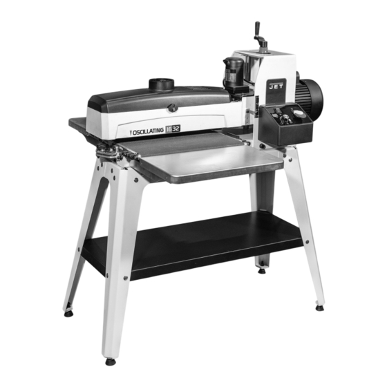
- Page 1 Operating Instructions and Parts Manual Drum Sander Model JWDS-1632OSC Shown with optional infeed/outfeed tables 427 New Sanford Road LaVergne, Tennessee 37086 Part No. M-723525 Ph.: 800-274-6848 Edition 1 12/2022 www.jettools.com Copyright ©2022 JET...
-
Page 2: Important Safety Instructions
5. Do not use this drum sander for other than its area and non-glare, overhead lighting. intended use. If used for other purposes, JET 19. Keep the floor around the machine clean and disclaims any real or implied warranty and holds free of scrap material, oil and grease. -
Page 3: About This Manual
Additional knowledge may be obtained from experienced users or trade articles. Whatever accepted methods are used, always make personal safety a priority. If there are questions or comments, please contact your local supplier or JET. JET can also be reached at our web site: www.jettools.com. -
Page 4: Table Of Contents
15.2.1 JWDS-1632OSC Conveyor Table Assembly – Exploded View ............27 15.2.2. JWDS-1632OSC Conveyor Table Assembly – Parts List ..............27 15.3.1 JWDS-1632OSC Infeed and Outfeed Tables (OPTIONAL) – Exploded View ......... 28 15.3.2 JWDS-1632OSC Infeed and Outfeed Tables (OPTIONAL) – Parts List .......... 28 15.4.1 JWDS-1632OSC Open Stand Assembly –... -
Page 5: Specifications
4.0 Specifications Model number ............................JWDS-1632OSC Stock numbers: Sander with Open Stand .......................... JT9-723525 Motor and electricals: Drum motor: Motor Type ................totally enclosed fan cooled, induction, capacitor start Horsepower ..............................1-1/2 HP Phase ................................. single Voltage ................................ 115V only Cycle .................................. -
Page 6: Features And Terminology
Shipping Weight ..........................227 lb. (103.3 kg) The specifications in this manual were current at time of publication, but because of our policy of continuous improvement, JET reserves the right to change specifications at any time and without prior notice, without incurring obligations. -
Page 7: Setup And Assembly
Read and understand the entire contents of this manual before attempting set-up or operation! Failure to comply may cause serious injury. 6.0 Setup and Assembly Open boxes and check for shipping damage. Report any damage immediately to your distributor and shipping agent. -
Page 8: Assembling Stand
Figure 6-3: Assembly 6.3 Assembling Stand 6.4 Mounting Sander to Stand (Refer to Figure 6-3. If further clarification is needed, 1. Lift drum head assembly out of the box, and consult parts breakdown at back of this manual. temporarily rest it crosswise on top of stand. 1. -
Page 9: Infeed And Outfeed Tables (Optional Accessory)
(TIP: If you are using an after-market abrasive, use If stock slips on conveyor, the tables may be a new JET-supplied abrasive as a template to positioned too high. Lower tables to allow stock to quickly cut a new strip. Alternatively, a diagram is remain in contact with conveyor. -
Page 10: Electrical Connections
1. Press fastener lever (Figure 6-7) on outboard (left) end of drum and insert tapered end of abrasive through slit in fastener, as shown. Align tapered edge of abrasive strip with left edge of drum. Insert enough strip so that the right edge aligns with the reference notch;... -
Page 11: Extension Cords
8.0 Adjustments Disconnect sander from power source before making adjustments. 8.1 Drum Height Control Drum height and depth of cut are controlled by height adjustment handle (see Figure 5-1). Rotating handle clockwise lowers drum, counterclockwise Figure 7-1 raises it. One revolution of handle will move drum approximately 1/16”... -
Page 12: Inspecting Drum Alignment
8.4 Inspecting Drum Alignment 8.3.1 Belt Tension Adjustment 1. Unplug sander from power source. The sanding drum must be parallel to conveyor table for proper machine operation. The sanding drum 2. Adjust take-up screw nuts (Figure 8-2) with comes pre-aligned from the manufacturer. If a 5mm hex wrench. -
Page 13: Tension Roller Adjustment
8.4.1 Fine-Tuning Drum Alignment Too much tension roller pressure can result in a “snipe” mark, which is a visible line running across Note: This is an operational test for sanding boards the width of the board and located approximately 2- wider than the drum. -
Page 14: Basic Operating Procedure
9.3 Basic Operating Procedure Do not start drum while in 1. Establish depth of cut. contact with stock. 2. Start dust collection system. 3. Without changing drum height, turn on 3. Start sanding drum. conveyor and run the stock out from under the 4. -
Page 15: Maximum Performance Tips
When sanding stock with a cup or crown, place the crown up. This will stabilize the stock to help prevent The versatility designed into the JWDS-1632OSC tipping or rocking during sanding. After the crown drum sander allows it to be used for a variety of has been removed and the top is flat, turn the stock tasks that will boost return on your investment. -
Page 16: User-Maintenance
9.7.7 Stock Feeding Angle • Check all set screws for tightness on parts such as bearings, conveyor table, and couplings. Some pieces, because of their dimensions, will need to be fed into the machine at a 90° angle (perpendicular to drum). However, even a slight offset angle of stock will provide for more effective stock removal. -
Page 17: Conveyor Belt Replacement
Figure 10-6: Drum Removal Figure 10-3: Drum Removal 10.3 Conveyor Belt Replacement 5. Disconnect sander from power. 6. Raise drum to highest position. 7. Turn take-up screws (Figure 8-2) on both sides of conveyor to relieve belt tension and slide the driven roller fully inward. -
Page 18: Commutator Brush Inspection
Step 1: Check conveyor drive roller and driven roller 4. Pull out brush and inspect. Brush should be to make sure they are parallel to surface of conveyor replaced if any of the following are discovered: table. To do this, first center conveyor belt on the •... -
Page 19: Tracker Kit
8. Install second tracker opposite the first. Use 11.0 Tracker Kit both trackers unless the second one does not fit in conveyor or unless conveyor belt is Stock No.: PM2244-213 damaged. 9. Turn conveyor table right-side up and reposition Trackers dramatically reduce tracking adjustments it onto sander. -
Page 20: Abrasives
When cleaning, also pre-cut lengths or in the convenient Ready-To-Cut brush the stick crumbs from the drum while it is still pre-marked box. Your JET dealer can recommend rotating. the best choice for your application. In some cases, heavy loaded areas can be removed 12.1 Selecting Drum Abrasives... -
Page 21: Troubleshooting Jwds-1632Osc Drum Sander
13.0 Troubleshooting JWDS-1632OSC Drum Sander Symptom Possible Cause Correction * Drum motor won’t start No incoming current. Check connections at plug or circuit panel. when switch is activated. Safety key missing from switch. Install safety key. Low voltage. Check power line for proper voltage. - Page 22 Symptom Possible Cause Correction * Line or groove in stock. Inconsistent feed rate. Do not stop or change the feed rate while feeding stock. Snipe marks. Improper tension on rollers. Re-tension rollers. Sander burns wood. Abrasive strip is overlapped. Re-wrap abrasive strip. Abrasive is loaded.
-
Page 23: Optional Accessories
Non-proprietary parts, such as fasteners, can be found at local hardware stores, or may be ordered from JET. Some parts are shown for reference only and may not be available individually. -
Page 24: Jwds-1632Osc Head Assembly - Exploded View
15.1.1 JWDS-1632OSC Head Assembly – Exploded View... -
Page 25: Jwds-1632Osc Head Assembly - Parts List
15.1.2 JWDS-1632OSC Head Assembly – Parts List Index No Part No Description Size 1 ....JWDS2244-102 ... Socket Head Cap Screw ..........M6 x 1.0P x 16L ....2 2 ....JWDS1632-103 ... Drum Carriage Hinge ................... 2 3 ....40317-15 ...... Spring Pin ..............3 x 14L ......4 4 .... - Page 26 ....JT1-74 ......Motor Label (not shown) ..................1 ....LM000360 ....Oscillating Motor Label (not shown) ..............1 ....JT1-75 ......ID Label, JWDS-1632OSC (not shown) ............... 1 ....JT1-76 ......JET Logo (not shown) ..................1 ....
-
Page 27: Jwds-1632Osc Conveyor Table Assembly - Exploded View
15.2.1 JWDS-1632OSC Conveyor Table Assembly – Exploded View 15.2.2 JWDS-1632OSC Conveyor Table Assembly – Parts List Index No Part No Description Size 1 ....JT1-78 ....... Belt Motor ..................... 1 2 ....F010839 ....Socket Head Flat Screw ........#10-32 x 1/2”L .... 4 3 .... -
Page 28: Jwds-1632Osc Infeed And Outfeed Tables (Optional) - Exploded View
15.3.1 JWDS-1632OSC Infeed and Outfeed Tables (OPTIONAL) – Exploded View 15.3.2 JWDS-1632OSC Infeed and Outfeed Tables (OPTIONAL) – Parts List Index No Part No Description Size ....723521 ....... Infeed/Outfeed Tables (includes #1-8) ............1 ....JWDS1632-401 ..Extension Table ..................... 2 2 .... -
Page 29: Jwds-1632Osc Open Stand Assembly - Exploded View
15.4.1 JWDS-1632OSC Open Stand Assembly – Exploded View 15.4.2 JWDS-1632OSC Open Stand Assembly – Parts List Index No Part No Description Size ....JT1-81 ......Open Stand Assembly ................... 1 1 ....JWDS1632-301 ..Leg ........................ 4 2 ....JWDS1632-302 ..Short Rail ....................... 2 3 .... -
Page 30: Electrical Connections For Jwds-1632Osc
16.0 Electrical Connections for JWDS-1632OSC... -
Page 31: Warranty And Service
JET sells through distributors only. The specifications listed in JET printed materials and on official JET website are given as general information and are not binding. JET reserves the right to effect at any time, without prior notice, those alterations to parts, fittings, and accessory equipment which they may deem necessary for any reason ®... - Page 32 427 New Sanford Road LaVergne, Tennessee 37086 Phone: 800-274-6848 www.jettools.com...
Need help?
Do you have a question about the JWDS-1632OSC and is the answer not in the manual?
Questions and answers