
Related Manuals for Woodward 3103


Summary of Contents for Woodward 3103
- Page 1 Released Product Manual 26734 (Revision H, 7/2022) Original Instructions 3103 Gas Valve with EM35MR Electric Powered Actuator Installation and Operation Manual...
- Page 2 Revisions— A bold, black line alongside the text identifies changes in this publication since the last revision. Woodward reserves the right to update any portion of this publication at any time. Information provided by Woodward is believed to be correct and reliable. However, no responsibility is assumed by Woodward unless otherwise expressly undertaken.
-
Page 3: Table Of Contents
3103 Gas Valve ............................21 Water Ingress Protection ..........................22 4. A ................23 HAPTER CTUATOR ALVE ALIBRATION EM35MR Actuator/3103 Gas Valve with Driver ..................23 5. T ............25 HAPTER ROUBLESHOOTING AND IELD EPLACEMENT General ................................ 25 ... - Page 4 Released Manual 26734 3103 Gas Valve with EM35MR Actuator Illustrations and Tables Figure 2-1a. EM35MR Actuator/3103 Gas Valve/Resolver Outline (NPT electrical conduit entries) ..11 Figure 2-1b. EM35MR Actuator/3103 Gas Valve/Resolver Outline ............12 Figure 2-2a. EM35MR Actuator/3103 Gas Valve/Resolver Outline ............13 ...
-
Page 5: Warnings And Notices
Released Manual 26734 3103 Gas Valve with EM35MR Actuator Warnings and Notices Important Definitions This is the safety alert symbol used to alert you to potential personal injury hazards. Obey all safety messages that follow this symbol to avoid possible injury or death. -
Page 6: Electrostatic Discharge Awareness
Do not touch the components or conductors on a printed circuit board with your hands or with conductive devices. To prevent damage to electronic components caused by improper handling, read and observe the precautions in Woodward manual 82715 , Guide for Handling and Protection of Electronic Controls, Printed Circuit Boards, and Modules. -
Page 7: Regulatory Compliance
States relating to equipment and protective systems intended for use in potentially explosive atmospheres Zone 1: II 2 G, Ex db IIB T3 Gb SIRA 13ATEX1188X EM35/EM35MR Actuator and 3103 Valve assemblies incorporating the minimum position switch are not suitable for use in an ATEX environment. - Page 8 Released Manual 26734 3103 Gas Valve with EM35MR Actuator Special Conditions for Safe Use Wiring must be in accordance with North American Class I, Division 1 or 2 or European Zone 1 wiring methods as applicable, and in accordance with the authority having jurisdiction.
- Page 9 Released Manual 26734 3103 Gas Valve with EM35MR Actuator The surface of this product can become hot enough or cold enough to be a hazard. Use protective gear for product handling in these circumstances. Temperature ratings are included in the specification section of this manual.
-
Page 10: Chapter 1. General Information
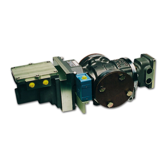
3103 Gas Valve The 3103 Gas Valve is a stainless-steel valve capable of metering gas flow between 23 kg/h and 18 144 kg/h (50 lb/h and 40 000 lb/h). The valve is designed to bolt into a 50 mm (2 inch) line by means of 0.625- 11 UNC 2B tapped holes. -
Page 11: Em35Mr Actuator
M25 x 1.5 conduit connections. Applications The 3103/EM35MR is well suited for metering flow to a gas turbine that is in continuous operation. When used in applications where the turbine is frequently in a standby mode, remove power from the valve, or place it in a slow cycle relubrication mode. -
Page 12: Chapter 2. Installation
Installation Unpacking Be careful when unpacking the EM 24 V Digital Driver and EM35MR actuator/3103 gas valve. Check the devices for signs of damage such as bent or dented case and loose or broken parts. If damage is found, notify the shipper immediately. The devices may be stored in their original shipping containers until they are ready for installation. -
Page 13: Figure 2-1A. Em35Mr Actuator/3103 Gas Valve/Resolver Outline (Npt Electrical Conduit Entries)
Released Manual 26734 3103 Gas Valve with EM35MR Actuator Figure 2-1a. EM35MR Actuator/3103 Gas Valve/Resolver Outline (NPT electrical conduit entries) Woodward... -
Page 14: Figure 2-1B. Em35Mr Actuator/3103 Gas Valve/Resolver Outline
Released Manual 26734 3103 Gas Valve with EM35MR Actuator Figure 2-1b. EM35MR Actuator/3103 Gas Valve/Resolver Outline (NPT electrical conduit entries) Woodward... -
Page 15: Figure 2-2A. Em35Mr Actuator/3103 Gas Valve/Resolver Outline
Released Manual 26734 3103 Gas Valve with EM35MR Actuator Figure 2-2a. EM35MR Actuator/3103 Gas Valve/Resolver Outline (metric electrical conduit entries) Woodward... -
Page 16: Figure 2-2B. Em35Mr Actuator/3103 Gas Valve/Resolver Outline
Released Manual 26734 3103 Gas Valve with EM35MR Actuator Figure 2-2b. EM35MR Actuator/3103 Gas Valve/Resolver Outline (metric electrical conduit entries) Woodward... -
Page 17: Figure 2-3A. Em35Mr Actuator/3103 Gas Valve 900 Psig Ped/Resolver Outline
Released Manual 26734 3103 Gas Valve with EM35MR Actuator Figure 2-3a. EM35MR Actuator/3103 Gas Valve 900 psig PED/Resolver Outline (NPT electrical conduit entries) Woodward... -
Page 18: Figure 2-3B. Em35Mr Actuator/3103 Gas Valve 900 Psig Ped/Resolver Outline
Released Manual 26734 3103 Gas Valve with EM35MR Actuator Figure 2-3b. EM35MR Actuator/3103 Gas Valve 900 psig PED/Resolver Outline (NPT electrical conduit entries) Woodward... -
Page 19: Em Actuator/3103 Gas Valve Installation
Make sure to allow adequate room for required wiring and that the wiring and valve/actuator are accessible for service. There are two overboard drains on the 3103 valves (see Figures 2-1/2-2/2-3). One is to be plumbed to an area outside the turbine enclosure. Use the overboard drain most convenient for your installation and plug the one that is not used. -
Page 20: Electrical Connections
See application note 50532, EMI Control in Electronic Governing Systems, for more information. Installations with severe electromagnetic interference (EMI) may require shielded cable run in conduit, double shielded wire, or other precautions. Contact Woodward for more information. EXPLOSION HAZARD—Do not connect or disconnect while circuit is live unless area is known to be non-hazardous. - Page 21 Released Manual 26734 3103 Gas Valve with EM35MR Actuator EXPLOSION HAZARD—For Zone 1 / Division 1 products: Using proper torque is very important to ensure that the unit seals properly. Actuator cover bolt torque is: 0.250-28 socket head cap screw = 9.2 Nm (81 lb-in) M6 x 1 socket head cap screw = 8.0 Nm (71 lb-in)
-
Page 22: Figure 2-4. Wago 264 Series Terminal Block
Released Manual 26734 3103 Gas Valve with EM35MR Actuator Insert screwdriver into the operating slot up to the stop. Insert the screwdriver into the operating slot up to the stop. Use the screwdriver blade to hold the clamping spring open until introducing the conductor into the clamping unit. -
Page 23: Chapter 3. Description Of Operation
Released Manual 26734 3103 Gas Valve with EM35MR Actuator Chapter 3. Description of Operation EM35MR Actuator The EM35MR electric actuator is comprised of a brushless dc motor, a clutch assembly, a gearhead assembly, and an explosion proof housing. The brushless dc motor uses Samarium Cobalt permanent magnets bonded and sleeved to the rotor. -
Page 24: Water Ingress Protection
Properly protect the 3103/EM35MR valve assembly from this water spray. 2. Conduit Fittings: Woodward recommends using rigid or flexible conduit to route the actuator wiring. Woodward also recommends using watertight conduit fittings when installing the wiring to the actuator. -
Page 25: Chapter 4. Actuator/Valve Calibration
(serial number and date code) must match the valve identification. For non-DLE applications, Woodward offers a series of standard 3103/EM35MR valves. From the factory, these valves have the minimum and maximum stops set outside the normal operating window of 0 to 60 degrees valve travel, and the flow calibration schedule is not for a specific application. - Page 26 (4) 3103 valve calibration files (*.vlv) should not be edited. Editing these files can create an unstable operational mode and may result in erratic behavior or excessive fuel delivery to the engine.
-
Page 27: Chapter 5. Troubleshooting And Field Replacement
Problems with the 3103/EM35MR assembly will usually show up as faults in the driver. Refer to the appropriate EM 24 V Driver manual (26159) for detailed fault information. -
Page 28: Procedure For Em35 Actuator Field Replacement
5/16” hex Allen wrench 3/8” drive torque wrench, capable of 33.2 Nm (24.5 lb-ft) Procedure 1. Locate the coupling assembly between the 3103 gas valve and the EM35 actuator; viewed through the long vertical slot in the adapter housing. Adapter Housing... -
Page 29: Figure 5-2. Identifying The Coupling Clamp Screw
Released Manual 26734 3103 Gas Valve with EM35MR Actuator Figure 5-2. Identifying the Coupling Clamp Screw 3. Using the 5/16” Allen wrench, remove the five socket head cap screws and lock washers that mount the EM35 actuator to the adapter housing. Remove the EM35 actuator from the assembly. - Page 30 Released Manual 26734 3103 Gas Valve with EM35MR Actuator 5. Once the actuator is in proper position, re-install the five socket head cap screws and lock washers removed in step 3. Torque the bolts to 33.2 Nm (24.5 lb-ft). 6. Using the 3/16” long ball hex driver and torque wrench, tighten the socket head cap screw on the coupling at the EM35 output shaft.
-
Page 31: Chapter 6 Valve Sizing -Non -Dle Applications
Released Manual 26734 3103 Gas Valve with EM35MR Actuator Chapter 6 Valve Sizing-Non-DLE Applications Determination of Effective Area In order to choose the proper size of valve for an application, the effective area required to meet your maximum flow requirement must first be determined. The effective area is determined using the following equations. -
Page 32: Valve Sizing And The Effective Area Tables
100 % travel row for the applicable pressure ratio column. Woodward recommends using no less than 60 % valve travel for the full control range. Using less than that could cause instability problems as the system attempts to control at very low increments of travel. -
Page 33: Determining The Demand Required To Achieve Specific Flows
The algorithm used for sizing and demand value determination used in the standard valve application programs available for the 3103 is the same as that described above. However, the program makes use of a valve inlet pressure compensation algorithm that enhances the accuracy of the calculation. This compensation scheme is not easily implemented in a manual system as described here. - Page 34 Released Manual 26734 3103 Gas Valve with EM35MR Actuator Table 6-1. 3103 1.0 in² port, Effective Area Valve angle = Resolver Feedback Angle – Resolve Offset Angle Resolver Offset Angle = ~20 degrees 4 mA = 0° valve angle = 0 % valve position = ~20 resolver angle min stop = –2 degrees valve angle...
- Page 35 Released Manual 26734 3103 Gas Valve with EM35MR Actuator Table 6-2. 3103 1.5 in² port, Effective Area Valve angle = Resolver Feedback Angle – Resolve Offset Angle Resolver Offset Angle = ~20 degrees 4 mA = 0° valve angle = 0 % valve position = ~20 resolver angle min stop = –2 degrees valve angle...
- Page 36 Released Manual 26734 3103 Gas Valve with EM35MR Actuator Table 6-3. 3103 2.0 in² port, Effective Area Valve angle = Resolver Feedback Angle – Resolve Offset Angle Resolver Offset Angle = ~20 degrees 4 mA = 0° valve angle = 0 % valve position = ~20 resolver angle min stop = –2 degrees valve angle...
-
Page 37: Chapter 7. Maintenance
Chapter 7. Maintenance There are no critical maintenance items in the 3103/EM35MR gas valve assemblies, such as filters that should be changed, etc. Visually inspect the valve assembly in accordance with your specific maintenance schedule. Each site must determine the appropriate schedule based on the severity of the service conditions. -
Page 38: Chapter 8. Product Support And Service Options
An Authorized Independent Service Facility (AISF) provides authorized service that includes repairs, repair parts, and warranty service on Woodward's behalf. Service (not new unit sales) is an AISF's primary mission. A Recognized Turbine Retrofitter (RTR) is an independent company that does both steam and gas turbine control retrofits and upgrades globally, and can provide the full line of Woodward systems and components for the retrofits and overhauls, long term service contracts, emergency repairs, etc. -
Page 39: Returning Equipment For Repair
All repair work carries the standard Woodward service warranty (Woodward Product and Service Warranty 5-01-1205) on replaced parts and labor. -
Page 40: Replacement Parts
The unit serial number, which is also on the nameplate Engineering Services Woodward offers various Engineering Services for our products. For these services, you can contact us by telephone, by email, or through the Woodward website. Technical Support ... -
Page 41: Technical Assistance
3103 Gas Valve with EM35MR Actuator Technical Assistance If you need to contact technical assistance, you will need to provide the following information. Please write it down here before contacting the Engine OEM, the Packager, a Woodward Business Partner, or the Woodward factory: General... -
Page 42: 3103/Em35Mr Specifications
3103 Gas Valve with EM35MR Actuator 3103/EM35MR Specifications The EM35MR electric actuator was designed for the positioning of Woodward gas and liquid valves equipped with resolver feedback. The actuator requires a final driver for driving the motor and for closed loop control. -
Page 43: Revision History
Released Manual 26734 3103 Gas Valve with EM35MR Actuator Revision History Changes in Revision H— Replaced all declarations Changes in Revision G— Replaced a DoC Changes in Revision F— Added a new paragraph and a WARNING signal word box at the end of the Regulatory Compliance section. -
Page 44: Declarations
Released Manual 26734 3103 Gas Valve with EM35MR Actuator Declarations Woodward... - Page 45 Released Manual 26734 3103 Gas Valve with EM35MR Actuator Woodward...
- Page 46 Released Manual 26734 3103 Gas Valve with EM35MR Actuator Woodward...
- Page 47 Released Manual 26734 3103 Gas Valve with EM35MR Actuator Woodward...
- Page 48 Released Manual 26734 3103 Gas Valve with EM35MR Actuator Woodward...
- Page 49 Released Manual 26734 3103 Gas Valve with EM35MR Actuator Woodward...
- Page 50 Released Manual 26734 3103 Gas Valve with EM35MR Actuator This Page Intentionally Left Blank Woodward...
- Page 51 Released Manual 26734 3103 Gas Valve with EM35MR Actuator This Page Intentionally Left Blank Woodward...
- Page 52 Email and Website—www.woodward.com Woodward has company-owned plants, subsidiaries, and branches, as well as authorized distributors and other authorized service and sales facilities throughout the world. Complete address / phone / fax / email information for all locations is available on our website.
Need help?
Do you have a question about the 3103 and is the answer not in the manual?
Questions and answers