Table of Contents
Advertisement
Quick Links
Advertisement
Table of Contents

Related Manuals for quadient MACH 6


Summary of Contents for quadient MACH 6
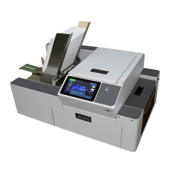
- Page 1 User Guide Digital Color Inkjet Printer MACH 6...
-
Page 2: Safety Precautions
In addition, follow any specific occupational safety and health standards for your workplace or area. This manual is intended solely for the use and information of Quadient, its designated agents, customers, and their employees. The information in this guide was obtained from several different sources that are deemed reliable by all industry standards. -
Page 3: Table Of Contents
TABLE OF CONTENTS SAFETY PRECAUTIONS SECTION 1 – Getting Acquainted Front View Entry End & Connections View Print Engine View (Under Printhead Door) Ink Tank View (Behind Ink Tank Door) Print Zone View (Under Clamshell) SECTION 2 – Installing Printer Transport Inspection Tools Needed Choose a Location... - Page 4 TABLE OF CONTENTS Using Printer Toolbox Opening the Toolbox Toolbox Features Drop-Down Menu Options View Drop-Down Maintenance Drop-Down Service Drop-Down Test Print Drop-Down Printer Driver Properties General Tab Layout Tab Color Tab Import/Export Tab SECTION 4 – Software Setup Information General Software Setup Info Adobe ®...
- Page 5 TABLE OF CONTENTS Appendix A – Printer Specifications Appendix B – Supplies and Optional Hardware Appendix C – Backup/Transfer Port Appendix D – Small Media Guide Kit Appendix E – Extended Rear Media Support Guide Appendix F – Magnetic Media Support Assembly Appendix G –...
-
Page 6: Section 1 - Getting Acquainted
SECTION 1 GETTING ACQUAINTED SECTION 1 – Getting Acquainted Front View Touchscreen Display (Control Panel) – Displays Menu and information about Printer status. You can set Printer features and control Printer functions from this display. Printhead Door – Provides access to Print Engine, Printhead and Service Station. NOTE: All doors must remain shut when printer is busy (printing, performing maintenance). -
Page 7: Entry End & Connections View
SECTION 1 GETTING ACQUAINTED Back Panel Entry End & Connections View Media Side Guide - Inner – Used to guide inner edge of Media. Media Side Guide - Outer – Used to guide outer edge of media. Feeder/Entry Sensor Assembly (adjustable) – Contains two sensors. Feeder Sensor is used to control when next piece feeds. -
Page 8: Print Engine View (Under Printhead Door)
SECTION 1 GETTING ACQUAINTED Print Engine View (Under Printhead Door) Service Station Sled Motor – Moves Service Station in and out from under Printhead Assembly for inspection, cleaning or service. Ink Revolver Couplings – Connect ink hoses to Printhead Cartridge. Printhead Latch extends and retracts couplings from Printhead. -
Page 9: Ink Tank View (Behind Ink Tank Door)
SECTION 1 GETTING ACQUAINTED Ink Tank View (Behind Ink Tank Door) Clamshell Latch – Used to release and open Clamshell to clear media jams, install/exchange Print Platen & Drip Tray and cleaning. Pull Latch out to release. Open Clamshell slowly to allow “Sump Pump” to remove waste ink from Service Station Tray and avoid ink spills. -
Page 10: Print Zone View (Under Clamshell)
SECTION 1 GETTING ACQUAINTED Print Zone View (Under Clamshell) Entry Sensor Reflector – Reflects sensor beam back to Media Entry Sensor. The leading edge of the media is detected as media passes between Entry Sensor and Reflector. Paperpath Surface – Flat metal surface supports media for smooth transport through Print Area. -
Page 11: Section 2 - Installing Printer
SECTION 2 INSTALLING PRINTER SECTION 2 – Installing Printer Before using Printer: Conduct Transport Inspection. Upon delivery, inspect packaging and report any issues to the Carrier. • Gather Tools • • Choose a location for Printer Unpack and verify Accessory Box contents •... -
Page 12: Transport Inspection
SECTION 2 INSTALLING PRINTER Transport Inspection The printer is shipped in appropriate packaging so that, under normal shipping conditions, it reaches its destination without damage. NOTICE: Report damage to the carrier. The carrier is liable for any damage during transport. Transport and storage should take place under the following conditions: - At temperatures between -25°C and +50°C (-13 °F to 122 °F). -
Page 13: Unpacking
SECTION 2 INSTALLING PRINTER Unpacking Please refer to the unpacking sequence, shown below. NOTE: Packaging materials may vary slightly from what is shown below. Please save packaging in a safe place, for possible future use. Two people will be required to safely lift printer and place it onto a sturdy, level worktable. IMPORTANT: WORKTABLE SURFACE MUST BE LEVEL! Lift off Outer... -
Page 14: Contents Of Packaging
SECTION 2 INSTALLING PRINTER Contents of Packaging Items included with the MACH 6 Printer. Rear Media Support Guide/Sled Assembly (Thumbscrew and mounting screws attached to Printer) Ink Tanks (five, packed in foam molds) – Cyan, Magenta, Yellow, Black, Black Printhead Cartridge (shown removed from packaging) -
Page 15: Removing Shipping Materials
SECTION 2 INSTALLING PRINTER Removing Shipping Materials WARNING TO AVOID POSSIBLE DAMAGE TO PRINTER, DO NOT PLUG-IN OR POWER-UP PRINTER UNTIL ALL SHIPPING MATERIALS HAVE BEEN REMOVED. 1. Open the Printhead Door. 2. Locate and Remove the Foam Shipping Block, shown below. Color of foam block may vary. NOTE: Foam Shipping Block is used to secure Service Station Sled position during transport. -
Page 16: Install Print Platen & Drip Tray Assembly
SECTION 2 INSTALLING PRINTER Install Print Platen & Drip Tray Assembly NOTE: Absorbent material, within new Print Platens and Drip Tray, may have some ink deposits on them. This is normal. Assemblies are installed and tested during quality control process, then they are removed and packaged in accessories box. - Page 17 SECTION 2 INSTALLING PRINTER Install Print Platen & Drip Tray Assembly into Printer: 1. Open Ink Tank Door [A]. 2. Release, pull out on, Clamshell Latch [B], to release and raise Clamshell. 3. Insert tabs, at each end of Drip Tray, into frame slots [C] as shown here CAUTION It is extremely important that you get Drip Tray tabs into frame slots [C] and that Platen is sitting level.
-
Page 18: Attach Media Side Guides And Rear Media Support Guide/Sled
SECTION 2 INSTALLING PRINTER Attach Media Side Guides and Rear Media Support Guide/Sled 1. Attach Media Side Guides (Inner and Outer) A. Remove Screws from Mounting Blocks, as shown. NOTE: There is a button-head screw and a flathead screw on each block. Keep track of their locations. B. - Page 19 SECTION 2 INSTALLING PRINTER 2. Attach Rear Media Support Guide/Sled Assembly. A. Remove Knob [3] (thumb screw and washer) and two Flathead Screws [4] from Mounting Blocks, as shown below. Tip: It may be helpful to use an Adjustable Wrench, to hold the Nut from spinning, when removing these two screws.
-
Page 20: Connect Printer
SECTION 2 INSTALLING PRINTER Connect Printer Plugging in Printer Plug power cord into a compatible AC outlet that supplies • 100-240VAC, 50/60 Hz and provides earth ground. The use of a power protection device is highly recommended, to reduce • damage caused by voltage sags, surges and brown outs. -
Page 21: Install Ink Tanks
SECTION 2 INSTALLING PRINTER Install Ink Tanks The MACH 6 uses five Ink Tanks (two Black, one Cyan, one Magenta, and one Yellow). The Ink Tank is a delicate, precision device. Handle with extreme care to avoid damage. Ink Tank Anatomy WARNING! Ink in Ink Tanks may be harmful if swallowed. - Page 22 SECTION 2 INSTALLING PRINTER Procedure (Install Ink Tanks): This procedure assumes that you are installing Ink Tanks into a printer that doesn’t have any Ink Tanks installed. If you are replacing an empty Ink Tank, please refer to the section titled “Replacing ink tanks”. Install the Ink Tanks as follows: CAUTION Use powder-free nitrile gloves when working with the Ink Tanks.
-
Page 23: Install Printhead Cartridge
SECTION 2 INSTALLING PRINTER Install Printhead Cartridge Use this procedure to install the Printhead into a printer that doesn’t currently have a Printhead installed. If you are removing and or replacing a Printhead Cartridge, please refer to the section titled “Remove/Replace Printhead Cartridge”... - Page 24 SECTION 2 INSTALLING PRINTER CAUTION • Use powder-free nitrile gloves when working with the Printhead. • Use electrostatic discharge (ESD) protection when handling Printhead. • Hold Printhead Cartridge by handles ONLY. • DO NOT touch ink couplings, nozzle surface or electrical contacts. •...
- Page 25 SECTION 2 INSTALLING PRINTER The Printhead Cartridge is a delicate precision device. Handle with extreme care to avoid damage and issues that could degrade print quality. Please read through this entire procedure before attempting this process. NOTE: This procedure assumes all Ink Tanks are installed and recognized as containing 30% or more ink. IMPORTANT! PRINTER MAY NOT FULLY PRIME IF INK TANK(S) ARE LESS THAN 30% FULL.
- Page 26 SECTION 2 INSTALLING PRINTER 4. Fully open the released Printhead Latch [1]. This will fully retract the Ink Revolver Couplings. Ink Revolver Couplings are shown with Fluidic Cap Protectors [2] installed, in images below. WARNING If the Printhead Latch failed to release, don’t force the latch open.
- Page 27 SECTION 2 INSTALLING PRINTER 6. Remove Printhead from Packaging. [A] Carefully remove Printhead Cartridge from foil packaging. Tear foil at notch or cut the end with scissors. [B] Remove protective plastic cover. Hold Printhead by handle and unclip cover from Printhead.
- Page 28 SECTION 2 INSTALLING PRINTER 9. Carefully Close Printhead Latch [6]. Tip: There will be a little resistance when closing the Printhead Latch with a new system, since the coupling surfaces are not lubricated (no ink present). Close the Latch slowly to avoid damaging the rubber O-rings located inside the Ink Revolver Couplings.
- Page 29 SECTION 2 INSTALLING PRINTER 12. Watch the Touchscreen Display to identify when Printhead is finished priming. The Printhead icon [7] will turn from an outline (Printhead unprimed) to a solid orange color (Printhead primed) and ONLINE [8] will be displayed in the upper left corner of the Touchscreen.
-
Page 30: Install Printer Software (Driver & Toolbox)
3. Connect USB Flash Drive, supplied with Printer, to USB port on your computer. 4. Browse the USB Flash Drive. Locate and open the “MACH 6” folder. Locate and open the “S Series Driver” folder. Locate and run WinSetup.exe. Tip: For best results, Right-click and “run as administrator”. - Page 31 SECTION 2 INSTALLING PRINTER 6. License Agreement. Check “I accept…” then click “Next>”. 7. Printer Connections. Click “Configure to print using USB”. Then click “Next>”. 8. Installing Printer Software. Software download begins. 9. Would You Like to Install This Device Software? Click “Install”.
- Page 32 SECTION 2 INSTALLING PRINTER 11. Finished software installation. Do not check Print Test Page as Printer is not set up yet. If desired, you can check “Set this printer as the default printer” at this time. Click “Finish”. 12. Install Printer Software. Click “Exit”...
-
Page 33: Connecting Printer Via Network (Ethernet Connection)
SECTION 2 INSTALLING PRINTER Connecting Printer via Network (Ethernet Connection) Use this procedure to install the Print Driver for a Network connection. If you plan to connect printer via USB, please see section titled “Connecting Printer via USB”. NOTE: Copy the 12-digit Hardware ID number listed on the Printer(s), on the label just below Ethernet port, so you can identify Printer(s) in a later step. - Page 34 SECTION 2 INSTALLING PRINTER 10. Install Printer Software. Make sure computer system meets minimum requirements and you followed other instructions listed on screen. Click “Install Printer Software”. 11. License Agreement. Check “I accept…” then click “Next>”. 12. Printer Connections. Click “Configure to print using over the Network”.
- Page 35 SECTION 2 INSTALLING PRINTER 14. If an S Series Printer is not found or the “Other Printer” button, from previous step, was pressed, the window shown here will appear. Enter the Printer’s current “IP address” then click “Next”. Tip: You don’t need to enter a “Host name”...
-
Page 36: Section 3 - Operating Printer
SECTION 3 OPERATING PRINTER SECTION 3 – Operating Printer WARNING Before you start using the printer, please be sure you have properly installed the Print Platen and Drip Tray Assembly. Media Feed Setup Printer is equipped with four Sheet Separators, two Side Guides, and a Rear Media Support Guide with two different sized Wedge Extensions. -
Page 37: Position Media Side Guides (Inner And Outer)
SECTION 3 OPERATING PRINTER Position Media Side Guides (Inner and Outer) 1. Position Media Side Guide – Inner [B] to the desired position and secure it using the locking knob. Then lay a single piece of media into the hoper so it is positioned against Media Side Guide –... -
Page 38: Attach Media Support Wedge Extension
SECTION 3 OPERATING PRINTER Attach Media Support Wedge Extension Attach the appropriate Media Support Wedge Extension, if needed, to the Rear Media Support Guide/Sled, as shown below. No Media Support Wedge Extension – For media that is 6” to 17” in length. Examples: Letter sized (8.5”x11”) media feeding Short Edge First (SEF) #9, #10 envelopes feeding SEF... -
Page 39: Guide/Sled Positioning Scales & Sled Safety Stop
SECTION 3 OPERATING PRINTER Adjust Rear Media Support Guide/Sled Assembly 1. Adjust Rear Media Support Guide [F]. Loosen the locking knob and slide Guide right or left, to center Guide on the width of your media. Then secure locking knob. 2. -
Page 40: Load Media Into Feeder Section (Hopper)
SECTION 3 OPERATING PRINTER CAUTION To avoid damage to feed rollers, make sure the Rear Media Support Sled does not make contact with the feed rollers. A safety stop plate, on the tabletop, is provided to help prevent this from occurring. However, if you loosen the locking knob too much you may be able to accidently pass the Sled over this safety stop. -
Page 41: Position Feeder/Entry Sensor Assembly
SECTION 3 OPERATING PRINTER Position Feeder/Entry Sensor Assembly Printer is equipped with a repositionable assembly that contains the Feeder Sensor and Entry Sensor. Feeder Sensor is used to control when the next piece of media is fed. Entry Sensor detects the leading edge of the media as it enters into the Print Engine area, and it is used to measure/monitor media length. -
Page 42: Verify "Ignore Exit Sensor" Selection
SECTION 3 OPERATING PRINTER Verify “Ignore Exit Sensor” Selection Printer is equipped with an Exit Sensor that is used to help detect Media feeding issues. The Exit Sensor is a reflective sensor, which looks up at the underside of the media. It is located under the Exit Transport Cover, on the table-top, between Media Transport Belts. -
Page 43: Correcting Misfeeds And Jams In Printer
SECTION 3 OPERATING PRINTER Correcting Misfeeds and Jams in Printer Misfeeds (media feed hesitations, double feeds and overlapping media) can commonly be corrected by readjusting the Sheet Separators, checking/adjusting Media Thickness setting and verifying that the Print Platen & Drip Tray assembly is properly installed. -
Page 44: Using Printer Touchscreen Display
SECTION 3 OPERATING PRINTER Using Printer Touchscreen Display The Printer's Touchscreen can be used to check Printer status, monitor ink usage, configure network settings, print test prints, reprint stored jobs, to set media thickness and run maintenance tasks. NOTE: These functions and more can also be operated remotely from a computer using the Printer Toolbox. See “Using the Printer Toolbox”... -
Page 45: System Status Indicator
SECTION 3 OPERATING PRINTER System Status Indicator The upper left corner of Touchscreen [A] will show the System Status and status messages. The color of the box provides a quick reference for the user to identify if the printer needs assistance or not. Here are some common System Status Indicators and messages: ONLINE Green box indicates OK condition. -
Page 46: Job & Maintenance Status
SECTION 3 OPERATING PRINTER Job & Maintenance Status This left-middle section of the Touchscreen [C] displays Job & Maintenance Status Page - shows page count for current or most recent job. Maintenance - counts down pages until the next automatic Printhead maintenance (Mid Job Service) is performed by the Service Station. -
Page 47: Firmware, Date, Time, Relative Humidity Information
SECTION 3 OPERATING PRINTER Firmware, Date, Time, Relative Humidity Information Small Text located at bottom left side of Touchscreen [F]. - Firmware shows current firmware version installed in printer. Example: S1_Mk2_R1.3.1: 0.0.47 = Firmware version R1.3.1 and RPI (UI) file version 0.0.47 - Date and Time shows current date and time. -
Page 48: Printer Status Icon
SECTION 3 OPERATING PRINTER Printer Status Icon This middle section of the Touchscreen [D] displays a Printer Icon. Within this Printer Icon you will find additional icons and symbols that represent the current status for the following components: Ink Valve, Media Sensors, Door Switches, Service Station, Printhead Height and Media Thickness settings. These icons and symbols can also be used to identify the locations of problems, such where a sensor is blocked by paper or if a Door is open. -
Page 49: Ink Tank Status
SECTION 3 OPERATING PRINTER Ink Tank Status This right side of the Touchscreen [E] displays the Ink Tank Status. Ink Levels: The system will display the calculated value (percentage) of available ink for each Tank. NOTE: When the value of any Ink Tank reaches 10% the numbers will turn RED. When the calculated value reaches zero (out) the printer will stop feeding/printing until the Ink Tank is replaced. -
Page 50: Touchscreen Menu Choices And Features
SECTION 3 OPERATING PRINTER Touchscreen Menu Choices and Features When you touch the “Menu Button” [B] a drop-down list of Menu choices appears with the following selections: Job, Setup, Test Print, Maintenance, Wiper and System Test. Touch one of these Menu selections to display the corresponding Menu Feature Buttons [G]. Job Menu Tap to open the “Media Setup”... - Page 51 SECTION 3 OPERATING PRINTER Media Setup - Tap to open the “Media Setup” Menu. In this menu you can set Media Thickness and Print Height. Select Ignore Exit Sensor, Select Fast Feeding and Feed Gap options. You can also Save and Load (recall) settings. Media Thickness - Moves the Clamshell up/down (0.1mm to 10mm) to accommodate media thickness.
- Page 52 SECTION 3 OPERATING PRINTER Print Height - Use to raise/lower the Printhead (in small increments) independently from the current Media Thickness setting. This feature can be useful for helping to avoid media to Printhead surface contact, which can cause “scuff marks” on the media.
- Page 53 SECTION 3 OPERATING PRINTER • A larger Feed Gap value (mm) will increase the gap between pieces, which may be necessary in order to reduce media feeding/printing issues. NOTE: Whenever you start or resume a print job the printer must measure the media length to determine when the feeder must be turned off/on, to obtain the selected Feed Gap value.
- Page 54 SECTION 3 OPERATING PRINTER Save/Load – Tap the Save/Load button to: Save current Media Setup settings as a • recallable selection (preset Name). Load a selection (preset Name) that was • previously saved. NOTE: Save/Load feature is available in printers with UI Software version 0.2.02 and higher.
- Page 55 SECTION 3 OPERATING PRINTER To Load (recall a preset), tap the “Apply” button that is located to the right of the desired selection. TIP: Up-Arrow can be used to re-arrange the order of the preset selections in the list. Exit button can be used to return to the Media Setup Menu without making any changes to the current settings. The Media Setup Menu will appear with the corresponding settings.
- Page 56 SECTION 3 OPERATING PRINTER Clear Error - Tap “Clear Error” to clear the current error condition. NOTE: Button will appear when an Error is detected and will disappear when Error is cleared. In some cases, you will not be able to clear the error until you have fixed the condition.
-
Page 57: Stored Jobs
SECTION 3 OPERATING PRINTER Stored Jobs Print jobs are saved to the Printer's Job Library by selecting the Printer Capture option under Job Management on the General Tab of the Printer Driver. Tip: Don’t forget to uncheck the “Printer Capture” feature when sending jobs that you don’t want stored on the printer. - Page 58 SECTION 3 OPERATING PRINTER Select a job by tapping the job icon or the list name. The Job Print Options screen opens. Tip: If you tap on the job name, shown here as “Unknown”, the “Rename Print Job” window will open, allowing you to change the job name.
-
Page 59: Setup Menu
SECTION 3 OPERATING PRINTER Setup Menu Tap the Menu button, then the Setup button to open the Setup screen. Release Printhead - Press to Releases Printhead Latch. NOTE: Button is only active when system is in a “deprimed” state. System Deprime - Pumps ink back into Ink Tanks (deprimes system) and then releases Printhead Latch. -
Page 60: Maintenance Menu
SECTION 3 OPERATING PRINTER Maintenance Menu Tapping Menu, then Maintenance opens the Maintenance screen. These buttons operate functions for Printer and Printhead maintenance. Inspect Sled – Moves Service Station out for inspection, cleaning or service. Printhead is also presented in Printhead Opening for inspection and manual cleaning. -
Page 61: System Test
SECTION 3 OPERATING PRINTER 4. Install the New Wiper Roller NOTE: If the new wiper roller has a plastic cover, you must remove the plastic cover before installing the wiper roller. Insert the gear-end of the wiper roller into the opening at the non-operator side of the Wiper Motor Assembly so it engages with the drive gears. -
Page 62: Using Printer Toolbox
SECTION 3 OPERATING PRINTER Using Printer Toolbox Once the “S Series Driver” is installed, you can access the Printer Toolbox remotely from a computer. You can check Printer status, monitor ink usage, perform diagnostic checks, print reports and run maintenance tasks on Printer from your computer. -
Page 63: Toolbox Features
SECTION 3 OPERATING PRINTER Toolbox Features [A] System Status Indicator and Drop-Down Menu Options (at top of screen). [B] Check Printer Status (across middle of screen). [C] Three often-used control buttons (at bottom of screen). Drop-Down Menu Options There are four Drop-Down Menus: View, Maintenance, Service and Test Print. The drop-down menus are available on every Toolbox screen allowing you to toggle between menus and select different Printer features and functions. - Page 64 SECTION 3 OPERATING PRINTER System Status This screen opens when you access the Toolbox. It provides information about the Printer. Status Indicator (upper left corner) shows Printer activity as ONLINE, ERROR, MAINT (maintenance), PRINTING or PAUSED. When “PRINTING”, the gray box (below Status Indicator) shows the name of the job being processed/printed.
- Page 65 SECTION 3 OPERATING PRINTER Printer Icon: Shows status of Media Sensors, located in the media feed path of the Printer, as well as status of the Ink Valve, Service Station, Printhead, Print Height, Printhead Door, Ink Tank Door and Media Thickness. Status icons (see icon key below) are used to alert the operator to the type and location of a problem.
- Page 66 SECTION 3 OPERATING PRINTER User Interface Use the items in this menu to adjust the following features. Mid-Job Servicing – Sets frequency (number of pages printed) before automatic Printhead maintenance occurs. In this example, maintenance will run after every 50 pages printed. Common range is between 50 and 250 pieces.
- Page 67 SECTION 3 OPERATING PRINTER Low Humidity The Low Humidity mode can be used to help reduce print quality issues caused by low relative humidity levels. When relative humidity levels are below 30% the RH value, located near the bottom left-hand corner of the printer’s Touchscreen, will flash RED, indicating that it would be a good idea to enable (turn on) low humidity mode.
- Page 68 SECTION 3 OPERATING PRINTER DISPLAY LANGUAGE: Selects language Toolbox will display. Click “Submit” after selecting language. FIRMWARE DOWNLOAD: This feature is used to update the firmware in the Printer. NOTE: Firmware and UI updates are normally provided in a set. To ensure compatibility, please be sure to update both items in the set.
- Page 69 SECTION 3 OPERATING PRINTER Ink Usage Displays the estimated amount of ink used along with other information for each job sent to the Printer. Also tracks estimated Page and Job Costs if information is entered in Job Cost Settings. WARNING! These features are provided for estimation purposes only. No guarantee of accuracy is expressed or implied.
- Page 70 SECTION 3 OPERATING PRINTER Service Menus Clicking Service Menus opens the Service Menus (Diagnostics) screen and service menu buttons. Diagnostics button: Click to check the status of the Printer. (See section titled “Diagnostics” for more details.) System Settings button: Click to view, enter or change settings to connect Printer to your network.
- Page 71 SECTION 3 OPERATING PRINTER System Settings Allows you to change the Printer’s network settings, set the Date and Time, set the Debug Log Level and set the Screensaver timeout. Network Settings – Permits you to view, enter or change the Printer’s internal and external network settings.
- Page 72 SECTION 3 OPERATING PRINTER Date and Time – Set the date and time or change the format of how the date and time will appear in the Toolbox and Touchscreen. To set or format Date and Time: 1. From the Toolbox, select “View” drop-down menu, click “Service Menus”...
- Page 73 SECTION 3 OPERATING PRINTER Screensaver – Set the amount of time (seconds) the Touchscreen will remain ON, when there is no user input, before going to “sleep mode”. NOTE: Touchscreen will go to “sleep mode” (black) when it has not been touched for the length of time (seconds) defined by the value for “ui_timeout_seconds”.
- Page 74 SECTION 3 OPERATING PRINTER History Logs (formerly Debug Logs) Use to access/open Printer Debug and Job logs. These files are valuable for diagnosing and troubleshooting problems. NOTE: If experiencing a persistent issue, you may be asked to provide a Debug Log from your printer. A technician may ask you to set the Debug Level to 1 or 2, and reproduce issue, before providing them with the Debug Log file.
- Page 75 SECTION 3 OPERATING PRINTER Scan Sensors Displays status for Sensors and Encoders, located throughout the Printer. (See chart below) Sensors are polled, and a new status line is provided, every few seconds. NOTE: The information shown in the “Scan Sensors” screen is meant for use by a technician. You may be asked to capture a screenshot of this screen, and send it to a technician, to aid in troubleshooting.
-
Page 76: Maintenance Drop-Down
SECTION 3 OPERATING PRINTER Maintenance Drop-Down Perform maintenance tasks on the Printer/Printhead. The printer automatically performs maintenance tasks to keep the printhead and ink system performing properly. The following features can be used, as needed, to provide supplemental maintenance. CAUTION: Over-use of these features can negatively affect print quality and printer performance. -
Page 77: Test Print Drop-Down
SECTION 3 OPERATING PRINTER Test Print Drop-Down Use to printout Printer Configuration values and Test Patterns. Test patterns are useful for troubleshoot printhead and print quality issues. Each printout displays information about the Printer. Print Setup Page – Prints a pattern that can be used to check printing alignments with the page. -
Page 78: Printer Driver Properties
SECTION 3 OPERATING PRINTER Printer Driver Properties Printer Driver works the same as any other Printer Driver for Windows. It does have some enhancements to help maximize the Printer's ability to print variable addressed pieces quickly and efficiently. Windows 8, 8.1, and 10: Once job is set up, click File, then Print. Window at right opens. -
Page 79: General Tab
SECTION 3 OPERATING PRINTER General Tab General tab lets you select: Orientation: Portrait (default), Landscape, • Rotate 180° and Mirrored. Tip: Instead of changing this setting from “Portrait” to “Landscape”, experiment with the drop-down list of Media “Size” selections (i.e., “6 x 9 in –... - Page 80 SECTION 3 OPERATING PRINTER Custom Sizes - Click on the “Custom Sizes” • button to create and save additional media sizes to suit your needs. Max Width = 8.77” Max Height = 40” NOTE: Do not exceed maximum paper size for Printer.
-
Page 81: Layout Tab
SECTION 3 OPERATING PRINTER Layout Tab Layout allows you change how document prints without changing original document. Resizing: • Original Size – No change to size. Custom Resize - Resizes original as a % of normal size. Printer prints document in size you selected regardless of paper size selected. - Page 82 SECTION 3 OPERATING PRINTER Using Layout Tab Printing Adjustments Top Adjustment moves image vertically (-4.98mm up to +200.02mm down) from top (leading edge) of media. (0.1mm increments) Left Adjustment moves image horizontally (+200.02mm right). Purge Bar Position* – In operation, Printhead spits a small amount of ink into gap between pieces to keep nozzles refreshed (hydrated).
-
Page 83: Color Tab
SECTION 3 OPERATING PRINTER Color Tab Color is used to adjust the color output of the Printer. Use the sliders to adjust Color Tone, Brightness and Saturation. The C, M, Y, K sliders adjust individual colors. Use Defaults to reset to 0 settings. Import/Export Tab Import/Export is used to preserve any custom Media Sizes, Watermarks and/or Print Settings you may have developed... -
Page 84: Section 4 - Software Setup Information
SECTION 4 SOFTWARE SETUP INFORMATION SECTION 4 – Software Setup Information General Software Setup Info Do NOT exceed the Min or Max media specifications of the printer: Minimum paper size printer can feed: 3" wide x 4" height (length). • Maximum paper size printer can feed: 10.5"... -
Page 85: Adobe ® Acrobat/Reader Setup Tips
SECTION 4 SOFTWARE SETUP INFORMATION Adobe ® Acrobat/Reader Setup Tips In general, printing a PDF from Adobe Acrobat/Reader is straight-forward and easy. However, there are a few limitations and quirks that you should be aware of. 1. Original PDF should be designed for the piece size and orientation you plan to use. Adobe Acrobat has some nice controls for changing orientation and adjusting the image size to fit the media size you select, but there are limits. -
Page 86: Setting Up A Job In Bulk Mailer
SECTION 4 SOFTWARE SETUP INFORMATION Setting Up a Job in Bulk Mailer ® Printer Driver Limitation: The developer of Bulk Mailer commonly develops printer drivers for use with their software product. However, in the case of the MACH 5 printer, they have not developed a driver for this model. Therefore, you will need to use the features within the “S Series Driver”... - Page 87 SECTION 4 SOFTWARE SETUP INFORMATION 8. The “Envelope Options” window will open. Double-click on “New Envelope/Letter Layout” 9. An envelope design window will open. Type a name (example: Digital Color Printer #10 LEF) into the Layout Name window. Enter these values: Page Width: 8.77 in.
- Page 88 SECTION 4 SOFTWARE SETUP INFORMATION 14. Add any additional items that you want printed to the “designer” screen. Drag and drop the items onto the layout, wherever you want them to be printed on the envelope. Click on Save. 15. Click on the "Go to Preview Mode" icon , located at the upper left-hand corner of the “designer”...
- Page 89 SECTION 4 SOFTWARE SETUP INFORMATION 19. In the “Mail Print Setup” window select “all pages” or the range of addresses you want to send to the printer. IMPORTANT! If you plan to select “Tray range” and use the “Pause Between” features, to pause the printer after each Bundle/Container, please be sure to select “Wait: for user”...
-
Page 90: #10 Envelope, Feeding Short-Edge First
SECTION 4 SOFTWARE SETUP INFORMATION #10 Envelope, Feeding Short-Edge First TIP: This is the direction a #10 envelope needs to be fed if you want to print on the full area of the envelope. 1. Open Bulk Mailer. 2. From the “Home” tab, select (double click) on the “mailing”... - Page 91 SECTION 4 SOFTWARE SETUP INFORMATION 9. The “Address Block Options” window will open. Select your Address Block option (example: Add a basic address block with barcode) Select your Barcode Type option: POSTNET or Intelligent Mail. Click Next. 10. The “Summary” window will open. Under Template Options select “Preview labels based on settings”...
- Page 92 SECTION 4 SOFTWARE SETUP INFORMATION 14. Click on the printer icon , to open the "Mail Print Setup" dialog box. Make sure the “S Series Driver” is selected as your "Printer". 15. From the “Mail Print Setup” window, Click on the “Advanced Settings” button. The “S Series Printer Driver Properties”...
-
Page 93: Section 5 - Maintenance
SECTION 5 MAINTENANCE SECTION 5 – Maintenance General, periodic maintenance is needed to keep Printer in good working order. This section covers how to care for the Printer and Printer Components (Ink Tanks, Printhead Cartridge, Service Station, etc.). It also covers Ink Tank, Printhead and Sheet Separator replacement. -
Page 94: Cleaning Print Engine
SECTION 5 MAINTENANCE Cleaning Print Engine Areas in Print Engine can become glazed with a buildup of dust, paper lint and accumulated ink and have to be cleaned regularly. Open Printhead Door. Open Ink Tank Door. Release the Clamshell Latch to open the Clamshell. Use a vacuum to pick up any loose debris. -
Page 95: Cleaning Clamshell Star Wheels
SECTION 5 MAINTENANCE Cleaning Clamshell Star Wheels As the printed media travels from the print area towards the exit end of the printer, it travels under the Star Wheel Assembly [B]. This assembly contains many pointed (starred) rollers/wheels that are designed to keep the printed media from making contact with anything that could smudge the wet image. -
Page 96: Cleaning Ink Tank Contacts & Prism
SECTION 5 MAINTENANCE Cleaning Ink Tank Contacts & Prism After reinstalling or replacing Ink Tanks the Ink Level indicators on the Touchscreen may not refresh. This may be due to a dirty Ink Tank Level Prism and/or QA Chip contacts on that Ink Tank(s). Clean contacts and prism as described below: 1. -
Page 97: Replacing Ink Tanks
SECTION 5 MAINTENANCE Replacing Ink Tanks Replace Ink Tanks when ink is low or runs out. 1. Look at the Touchscreen Display. Ink Tank Status information appears on the right side of the Touchscreen. Note that some or all of ink boxes may be low or empty. 2. -
Page 98: Ink Tank Storage
SECTION 5 MAINTENANCE Ink Tank Storage Ink Tank storage should take place, in the original/sealed packaging, under the following conditions: Long Term: 41°F to 113°F (5°C to 45°C) Short Term: -13°F to 158°F (-25°C to 70°C) Storage Temperature Range: NOTE: Cumulative storage duration below 41°F (5°C) or above 113°F (45°C) must not exceed 72 hours. -
Page 99: Cleaning The Printhead
SECTION 5 MAINTENANCE Cleaning the Printhead The Printhead is cleaned automatically during shut-down, power-up, Mid Job Servicing and other circumstances. If necessary, you can also force a printhead cleaning using the Quick/Normal/Full “Clean Printhead” features. These features can be accessed from the Toolbox, under the “Service” Tab, or from the Touchscreen, under the “Maintenance”... -
Page 100: Remove/Replace Printhead Cartridge
SECTION 5 MAINTENANCE Remove/Replace Printhead Cartridge IMPORTANT TO ENSURE OPTIMUM PRINTING PERFORMANCE, IT IS RECOMMENDED TO REPLACE THE WIPER ROLLER WHEN REPLACING THE PRINTHEAD. Use this procedure to remove and or replace a Printhead that is currently installed in the Printer. If the printer does not have a Printhead installed at this time, please refer to the section titled “Install Printhead Cartridge”. - Page 101 SECTION 5 MAINTENANCE 5. Once the old Printhead Cartridge has been removed, please refer to the section titled “Installing Printhead Cartridge”, to reinstall a Printhead or install a new Printhead Cartridge. If you plan to replace the Wiper Roller, please do this before installing the Printhead and priming the system.
-
Page 102: Printhead Storage
SECTION 5 MAINTENANCE Printhead Storage Printhead storage should take place, in the original/sealed packaging, under the following conditions: Long Term: 41°F to 113°F (5°C to 45°C) Short Term: -13°F to 140°F (-25°C to 60°C) Storage Temperature Range: NOTE: Cumulative storage duration below 41°F (5°C) or above 113°F (45°... -
Page 103: Inspecting The Service Station
SECTION 5 MAINTENANCE Inspecting the Service Station The Service Station cleans Printhead Cartridge of excess ink and debris, keeps Printhead hydrated and protected when not in use, and captures and removes ink used to keep nozzles clear. It moves out of the way of the Printhead during printing. -
Page 104: Inspect/Replace Waste Ink Tray
SECTION 5 MAINTENANCE Inspect/Replace Waste Ink Tray Waste Ink Tray catches and absorbs the waste ink produced by the system. This tray is filled with absorbent material. This Tray, or the absorbent material within the Tray, must be replaced when it becomes saturated. Please inspect routinely. -
Page 105: Preparing Printer For Transport
SECTION 5 MAINTENANCE Preparing Printer for Transport Please use this procedure if you ever need to transport the printer to a new location or ship the printer. Please refer to the appropriate sections in the manual for details on installing/removing items from the printer. Local relocation Transporting the printer from one room to another in the same building is considered a local relocation. - Page 106 SECTION 5 MAINTENANCE 3. Fully Open released Printhead Latch. This will fully retract the Ink Revolver Couplings. CAUTION IF PRINTHEAD LATCH IS NOT RELEASED, DO NOT PRY OR MANUALLY LIFT LATCH OR LATCH WILL BREAK. USE “SYSTEM DEPRIME” or “RELEASE PRINTHEAD” BUTTONS, FROM THE TOUCHSCREEN OR TOOLBOX, TO RELEASE PRINTHEAD LATCH.
- Page 107 SECTION 5 MAINTENANCE C. Remove Ink Tanks and Check/Replace Waste Ink Tray 1. Open Ink Tank Door (hinged at bottom). Open the Ink Tank Latches [A] and pull Ink Tank(s) [B] out of Printer. 2. Carefully package Ink Tanks. Place into individual, re- sealable plastic bags and then place into original foam packaging.
-
Page 108: Printer Maintenance Schedule
SECTION 5 MAINTENANCE PRINTER MAINTENANCE SCHEDULE General, periodic maintenance is needed to keep Printer in good working order. Many tasks can be performed by operators with basic supplies, no special tools needed. Other tasks should only be performed by trained service personnel. -
Page 109: Section 6 - Troubleshooting Guide
SECTION 6 TROUBLESHOOTING SECTION 6 – Troubleshooting Guide Troubleshooting Guides are provided to assist in solving any problems that might occur with Printer. We tried to make them as complete as possible. The best advice we can offer is to make sure that system is set up properly, before attempting to troubleshoot any problem. -
Page 110: Air In Printhead Nozzle Area
SECTION 6 TROUBLESHOOTING Air in Printhead Nozzle Area: Air in the printhead nozzles will show as jagged, irregular shaped lines of missing color. Lines are normally wider than one nozzle. Possible Solutions: • Press the “Full Clean Printhead” button, located in the Maintenance Menu. This can help dislodge, purge and remove air bubbles within the Printhead and Ink Tubes. -
Page 111: Clogged/Damaged/Dead Nozzles
SECTION 6 TROUBLESHOOTING Clogged/Damaged/Dead Nozzles: The Memjet printhead cartridge contains 70,400 inkjet nozzles. These nozzles are divided into ten rows, two rows of nozzles for each color channel. Due to the extremely high number of nozzles, it is not uncommon for some nozzles to become contaminated, dehydrated or clogged. -
Page 112: Color Mixing Issues
SECTION 6 TROUBLESHOOTING Color Mixing Issues: Color mixing will show as muddy, mottled or distorted (grainy) colors. Color mixing occurs when the ink from one color channel crosses over into another color channel. Since the inkjet nozzle rows are located very close to one another (ten rows of 7,040 nozzles, located within a 0.8 mm space), it is easy for partials or fibers to create bridges across color channels. -
Page 113: Scuff Marks
SECTION 6 TROUBLESHOOTING Scuff Marks Scuff Marks occur when the media makes contact with something (most commonly the Printhead) that has ink on it. Here is an example of “scuff marks” that occurred when the high points (thicker/puffier areas) on this #10 envelope made contact with the printhead. -
Page 114: Smudging Issues
SECTION 6 TROUBLESHOOTING Smudging Issues Smudging occurs when the wet image, on the media, makes contact with something (most commonly the printhead or upper exit rollers) before it is dry. This issue will also increase the chance for scuff marks. Here is an example of “smudging”... -
Page 115: Fuzzy/Distorted Print
SECTION 6 TROUBLESHOOTING Fuzzy/Distorted Print Fuzzy/distorted print can occur for a number of reasons, listed/shown below. Problem: Print Height value, in Media Setup, is set too high. Solution: Reduce Print Height value. Problem: Paper is buckling or bowing during the time of printing. Solution: Check that Print Platen and Drip Tray Assembly is proper installed. -
Page 116: Ink Tank(S)
SECTION 6 TROUBLESHOOTING Ink Tank(s) NOTICE: To avoid problems caused by an Ink Channel (ink tube) running dry, the Ink Tank will be flagged as “Out” before it is totally dry. Therefore, it is common for a small amount of ink to be left within the Ink Tank when the “Out”... -
Page 117: Memjet ® Printhead
SECTION 6 TROUBLESHOOTING Memjet Printhead ® CONDITION PROBLEM / CAUSE SOLUTION Missing parts of letters Air or debris blocking Nozzles. Clean Printhead using “Normal Clean or text. Printhead", found on the Printer Touchscreen or in Printer Toolbox. If problem persists run “Full Clean Printhead”. -
Page 118: Printer
SECTION 6 TROUBLESHOOTING Printer CONDITION PROBLEM / CAUSE SOLUTION Printer won’t Power-up Power cord disconnected. Check AC Power Cord connections, Main Power Switch, and Soft-Power Button. Main Power Switch is OFF. Check wall outlet for proper power. Didn’t press Soft-power button. - Page 119 SECTION 6 TROUBLESHOOTING Printer (continued) CONDITION PROBLEM / CAUSE SOLUTION Intermittent missing dots Automatic Printhead Set “Mid-Job Servicing” to a lower value. (lines, in direction of media Maintenance features need Set “KWS” to a higher level. travel) or changes in color, to be adjusted.
-
Page 120: Errors And Warnings
SECTION 6 TROUBLESHOOTING Errors and Warnings Printer Alert Window Messages Messages sent from Driver and displayed on PC screen in a small popup window. MESSAGE SOLUTION Wait until message disappears. Printer will start printing your job once cleaning Cleaning in Progress process is complete. -
Page 121: Toolbox System Status Messages
SECTION 6 TROUBLESHOOTING Toolbox System Status Messages Use the Touchscreen or Toolbox screen to quickly determine and locate a problem in the Printer. When a problem is detected, the Status Indicator will show ERROR in a box. • System Status will display the basic problem (in red). •... - Page 122 SECTION 6 TROUBLESHOOTING Toolbox System Status Messages (continued) SYSTEM STATUS SOURCE SOLUTION System Status: Indicates that Ink Tank Verify that Ink Tank Door is closed. DOOROPEN_INK Door is open. Make sure that Ink Tank Door switch (located at the upper right corner of the door) is activated when the Ink Tank Door is open and closed.
- Page 123 SECTION 6 TROUBLESHOOTING Toolbox System Status Messages (continued) SYSTEM STATUS SOURCE SOLUTION System Status: Motor that drives Restart Printer. MAINTENANCE_JAM component has detected If problem persists, call for Service. a problem or movement Tip: To define error, check Touchscreen is hindered. to see if it displays one of the following messages.
- Page 124 SECTION 6 TROUBLESHOOTING Toolbox System Status Messages (continued) SYSTEM STATUS SOURCE SOLUTION System Status: Printer Ready System is ready to accept jobs and print. ONLINE System Status: Change in media length Remove media from the Printer PAPERPATH_FEEDER detected by Feeder transport.
- Page 125 SECTION 6 TROUBLESHOOTING Toolbox System Status Messages (continued) SYSTEM STATUS SOURCE SOLUTION System Status: Change in media length Remove media from the Printer transport. PAPERPATH_PAGE_SEQUENCE detected. Check/adjust sheet separation. Reposition media or Feeder/Entry Sensor Shinny media surface or Assembly, so paper passes under hole in media.
-
Page 126: Appendix A - Printer Specifications
APPENDIX Appendix A – Printer Specifications Best: 1600 x 1600 DPI PRINT RESOLUTION Normal: 1600 x 800 DPI Over Speed OFF Up to 3,600 letter size pages per hour Up to 7,500 #10 envelopes per hour SPEED Over Speed ON (normal print quality Up to 4,500 letter size pages per hour burst speed) -
Page 127: Appendix B - Supplies And Optional Hardware
APPENDIX Appendix B – Supplies and Optional Hardware The following supply items and optional hardware are available from your Distributor: SUPPLIES PART # Printhead Cartridge M5PRINT Wiper Roller 123-2924 Black Ink Tank (printer requires 2) M5K250 Cyan Ink Tank M5C250 Magenta Ink Tank M5M250 Yellow Ink Tank... -
Page 128: Appendix C - Backup/Transfer Port
APPENDIX Appendix C – Backup/Transfer Port NOTE: This port may NOT be present on all MACH 6 Printers. The USB port, located on the front of the printer, can be used to backup stored Print Jobs. Backed-up Print Jobs can then be: Transferred (uploaded) to another MACH 6 printer. -
Page 129: Appendix D - Small Media Guide Kit
APPENDIX Appendix D – Small Media Guide Kit The Small Media Guide Kit (part # 47-900-05) is an optional accessory. It allows for feeding of smaller, narrower media such as business cards (2” W x 3.5" L, 50.8 mm W x 88.9 mm L). NOTE: 3.5”... -
Page 130: Appendix E - Extended Rear Media Support Guide
APPENDIX Appendix E – Extended Rear Media Support Guide The Extended Rear Media Support Guide (part # 47-116-06) is an optional accessory. It extends the support range of long media up to 19” (482.6 mm) for stiff media and up to 22"... - Page 131 APPENDIX 4. Install the Sled onto the Extended Rear Media Support Guide. a. Install the Support Nut [D] from below. b. While holding the Support Nut [D] into position, secure the Sled to the Support Nut using the Locking Knob and (2) screws [C], that were removed in Step 3.
-
Page 132: Appendix F - Magnetic Media Support Assembly
APPENDIX Appendix F – Magnetic Media Support Assembly The Magnetic Media Support Assembly (part # 47-116-25) is an optional accessory. The Magnetic Media Support Assembly fits over the Center Plate Support Bar. A strong magnet holds it tight against the Center Plate. Allows feeding of envelopes bottom edge first (i.e., flap is on the on trailing edge) to prevent the flap from opening, catching or skewing the envelope. -
Page 133: Appendix G - Adjustable Exit Wheels Assembly
APPENDIX Appendix G – Adjustable Exit Wheels Assembly The Adjustable Exit Wheels Assembly (part # 47-900-10) is an optional accessory that must be installed by a qualified service technician. It permanently replaces the existing “Exit Transport Cover”. 47-900-10 Exit Wheel Assembly Kit includes: (1) Right-hand Wheel Assembly (1) Left-hand Wheel Assembly (1) Exit Wheel Shaft... -
Page 134: Appendix H - Media Retainer Guide Kit
APPENDIX Appendix H – Media Retainer Guide Kit The Media Retainer Guide Kit (part # 47-900-15) is an optional accessory. Media Retainer Guides can be used to hold down uneven or wavy media as it feeds into the Printer, to help prevent media jams. They attach to the Media Thickness Cross Bar and adjust to fit media width. -
Page 135: Appendix I - Catch Tray
APPENDIX Appendix I – Catch Tray The Catch Tray (part # DT-420) is an optional accessory. DT-420 Catch Tray includes: • Catch Tray Stop (Media Stop) • Stop Mounting Bracket • Mounting Screw (Thumb Screw) • Tools Needed: None Attach Media Stop and Position Catch Tray With Catch Tray upright, reach under high side of Catch Tray with Stop Mounting Bracket. -
Page 136: Appendix J - Service Station Maintenance
APPENDIX Appendix J – Service Station Maintenance NOTICE Service Station Maintenance and Wiper Roller Replacement should only be performed by a qualified/trained person. Please contact your service representative to obtain training or to have them perform this service for you. It is very important that the components within the Service Station receive proper, routine maintenance. - Page 137 APPENDIX Removing and Cleaning Service Station Components Removing & Cleaning Capping Station: 1. Using the Touchscreen, select “Menu,” and tap “Maintenance” from the drop-down menu. Tap “Inspect Sled”. The Service Station Sled moves out from under the Printhead Carriage. 2. Open the Printhead Door. 3.
- Page 138 APPENDIX Removing & Cleaning Wiper Motor Assembly: 1. Using the Touchscreen, select “Menu,” and tap “Maintenance” from the drop-down menu. Tap “Inspect Sled”. The Service Station Sled moves out from under the Printhead Carriage. 2. Open the Printhead Door. 3. Press the Soft Power button to power-down the printer.
- Page 139 APPENDIX 12. Reconnect the Wiper Motor’s electrical connection [D] and make sure the connector and wiring are positioned inside the Sled and as low as possible. WARNING: If connector or wiring is not positioned properly it may contact the Printhead Carriage which may damage the Printhead or cause “Maintenance Jam”...
- Page 140 APPENDIX Replacing Wiper Roller: This procedure should only be used if you plan to replace the Wiper Roller without replacing the Printhead. NOTE: When a Printhead is replaced, it is assumed that a new Wiper Roller is also installed at that time. During the printhead priming process the new Wiper Roller is automatically conditioned (hydrated).
-
Page 141: Index
INDEX INDEX Control Buttons ............65 Control Panel Soft-Power Button ..........6 Adjust Touchscreen ........... 6, 44 Feeder/Entry Sensor ........... 41 Copies ..............79 Adjustable Exit Wheels Assembly ......133 Couplings, Ink Revolver ..........8 Adobe Acrobat ............85 Covers Adobe Reader ............ - Page 142 INDEX Ink Out ............. 122 Maintenance Jam ..........123 Half Speed ............... 80 Mech_Cancelpage ..........123 History Logs, Toolbox ..........74 Mech_Fail_Permanent ........123 Paper Exit Sensor ..........124 Paper Feed Timeout ......... 124 Paperpath Feed Servo ........125 Idle Timeout ............66 Paperpath Gap Servo........
- Page 143 INDEX Touchscreen ............50 Clean ..............94 Job Status ..............46 Reflector ............10 Media Setup ............. 51 Media Side Guide - Inner .......... 7 Media Side Guide - Outer .......... 7 KWS Setting ............66 Media Side Guides........... 37 Media Size ...............
- Page 144 INDEX Powering Down Printer ........... 20 Receptacle, Power ..........7 Powering OFF ............20 Sheet Separators ........... 7 Powering ON ............20 Shipping/Transporting ........105 Powering Up Printer ..........20 Star Wheels, Clean ..........95 Preparing Printer for Transport ......105 Supplies ............
- Page 145 INDEX Rear Media Support Guide/Sled Assembly ..... 39 Adjusting ............37 Receptacle, Power ............. 7 Remove/Replace ..........104 Reflector, Media Sensor .......... 10 Shipping Material Removal ........15 Relocation, Local ........... 105 Shipping/Transporting Printer ....... 105 Relocation, Remote ..........105 Shutdown Remove Toolbox ..............
- Page 146 INDEX Ink Usage ............69 Ink Tanks ............116 Maintenance Menu ..........76 Printer ............118, 119 Network Settings ..........71 Printhead ............117 Scan Sensors ............75 Troubleshooting Guide .......... 109 Service Menu ..........70, 76 Turning Power ON/OFF .......... 20 System Settings ..........
- Page 148 © Quadient August 17, 2023...
Need help?
Do you have a question about the MACH 6 and is the answer not in the manual?
Questions and answers
my display screen went out