Table of Contents
Advertisement
Quick Links
Solar Inverter
PVS-166-175-TL-US A.2 Version
Quick Installation Guide
In addition to what is explained in this quick installation guide, the safety and installation information provided in the product manual must be read and
followed. The technical documentation for the product is available at the website.
The device must be used in the manner described in the manual. If this is not the case the safety devices guaranteed by the inverter might be
ineffective.
Advertisement
Table of Contents

Related Manuals for Fimer PVS-166-TL-US


Summary of Contents for Fimer PVS-166-TL-US
- Page 1 Solar Inverter PVS-166-175-TL-US A.2 Version Quick Installation Guide In addition to what is explained in this quick installation guide, the safety and installation information provided in the product manual must be read and followed. The technical documentation for the product is available at the website. The device must be used in the manner described in the manual.
- Page 2 For more detailed information regarding proper installation and use of this product, refer to the product manual located at www.fimer.com. ATTENTION –...
-
Page 3: Table Of Contents
Table of Content 1. Reference number index 1.1 PVS-166/175-TL-US - External view 1.2 PVS-166/175-TL-US - External sides view 1.3 PVS-166/175-TL-US Power module- Internal view 1.4 PVS-166/175-TL-US Wiring box- Internal view 1.5 Communication board 2. Labels and Symbols 3. Models and range of equipment 4. - Page 4 13.7 Multifunction Relay connection (ALARM and AUX) 14. Description of LED panel 15. Commissioning 15.1 Commissioning via FIMER Installer for Solar Inverters mobile APP 15.2 Commissioning via Web User Interface 16. Arc fault detection 17. Grid support functions and Voltage & Frequency trip limits 38 18.
-
Page 5: Reference Number Index
Side latch DRM0 activation switch Wiring box front cover RS485 line 120Ohm termination res. LEDs panel FIMER RS485 service RJ45 connector (service only) AC disconnect switch (-SX2 only) Remote ON/OFF terminal block EGC connection point RS485 line terminal block AC opening (size 3” conduit) Ethernet connector 1 (RJ45) Service opening (size 3/4”... -
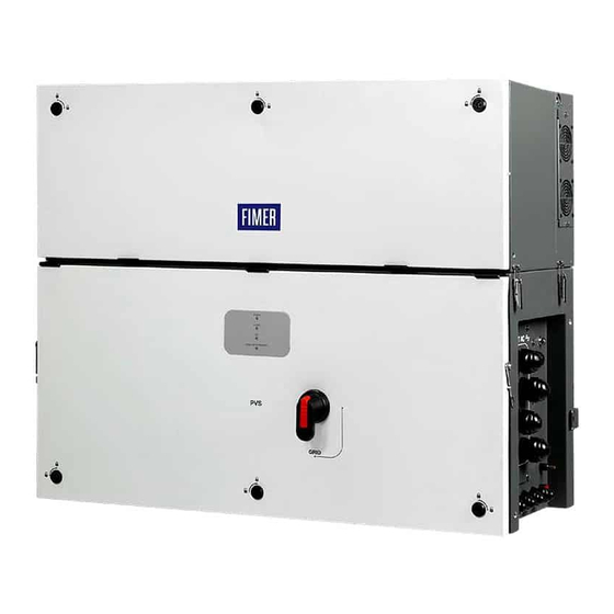
Page 6: Pvs-166/175-Tl-Us - External View
1.1 PVS-166/175-TL-US - External view Version with DC cable tray... -
Page 7: Pvs-166/175-Tl-Us - External Sides View
1.2 PVS-166/175-TL-US - External sides view 1.3 PVS-166/175-TL-US Power module- Internal view Version without protective cover Version with protective cover... -
Page 8: Pvs-166/175-Tl-Us Wiring Box- Internal View
1.4 PVS-166/175-TL-US Wiring box- Internal view... -
Page 9: Communication Board
1.5 Communication board... -
Page 10: Labels And Symbols
D. Powe Week/Year of manufacture E. Main technical data F. Certification marks Fimer S.p.A. Via Tortona, 25 - I 20144 Milano (MI) NOTE – An additional PN and SN label of the full system (power module + wiring box) is applied on the external packaging. This... - Page 11 The Communication Identification label (applied on the wiring box) is divided in two separate parts by a dashed line; take the bottom part and apply it on the plant documentation. (FIMER recommend to create a plant map and apply the Communication Identification label on it).
-
Page 12: Models And Range Of Equipment
Risk of injury due to the heavy weight of the equipment! FIMER usually stores and protects individual components by suitable means to make their transport and subsequent handling easier. Nonetheless, as a rule, it is necessary to turn to the experience of specialised staff to take charge of loading and unloading components. - Page 13 ATTENTION – Handling and installation operations shall be performed only by using the special tools and accessories provided with “PVS-175 Installation Kit” that has to be ordered separately. The use of these equipment are mandatory to safely install the inverter. Refer to “Kit of recommended spare parts” chapter content in the user manual for further information. ATTENTION –...
- Page 14 ATTENTION – Always consider the center of gravity of the enclosures while lifting. Center of gravity (power module) Center of gravity (wiring box) ATTENTION – In case of manual lifting it’s suggested to use a support plan (e.g. a table) to place the equipment during the lifiting operation, to allow the change of hands position.
-
Page 15: List Of Supplied Components
5. List of supplied components Available components for wiring box Multifunction and aux relay (33) connector (pre-installed on communication board (28)) Remote ON/OFF (38) and RS485 (39) connector (pre-installed on communication board (28)) Key tool for front covers quarter cam-lock (05) 1 + 1 Different keys are available based on the cover quarter cam locks (05) installed on the inverter M8 bolt and washers for EGC connection point (10) -
Page 16: Choice Of Installation Location
In case of opening when the unit is wet, avoid any water infiltration inside the unit, either in WB or PM. • All installations over 6500’ (2,000 meters) must be assessed by FIMER Technical Sales to determine the proper datasheet derating. -
Page 17: Distances
7.3 Distances on the right side and 30cm /12” on the left side. • Hardware and software maintenance on device entails removing the front cover. Check that the correct installation safety distances are observed in order to allow routine check and maintenance operations. -
Page 18: Wireless Signal Environmental Checks
7.5 Wireless signal environmental checks To install the protection covers place them over the wiring box openings and fix it using the 8 x M5 screws provided with the The inverter can be commissioned and monitored using the accessory kit. wireless communication channel. -
Page 19: Assembly Of The Inverterto The Bracket
• Use the two M8 screws with flat and spring washers (supplied) to • In case of use of “frame fixing brackets” (see picture below as fix the pieces of the bracket together. example) it will be possible to fix the bracket to the frame structure without drill any additional holes. -
Page 20: Opening The Wiring Box Cover
lifting device. Insert the heads of two rear attachment pins (14) (placed on the rear part of the power module) into the slots on the bracket (03). ATTENTION – Risk of injury due to the heavy weight of the equipment. Always consider the center of gravity of the enclosures while lifting. -
Page 21: Final Fastening Operations
• Open the Wiring box cover (07) and use the cover support • Remove the three M5 screws from the DC surge arrester plate brackets (15) to lock the cover (07) in open position. (21). • Rotate the DC surge arrester plate (21) as shown in the picture below. -
Page 22: Opening The Power Module Box Cover
8.7 Connection of the AC interface power • Close the Wiring box cover. cables (25) The AC interface power cable (32) (RST phases, PE and MID BULK) are situated into the cable housing on the top side of wiring box (02). 8.6 Opening the power module box cover •... -
Page 23: Connection Of The Interface Signal Connectors
8.9 Connection of the DC and AFD interface • Install the protective earth cable lug to the protection earth point interface cable (26) situated on the internal bottom side of power cables module (01), using the bolt with washer supplied in the power The DC interface cables (18) and AFD interface cables (59) are module installation kit, as shown in the following picture: situated into left side of Power module (01). - Page 24 damage. Check polarity before connecting each cable! • Pass the DC interface cables (18) into the same dedicated Always check correspondence of cables and board FASTON opening used for the AFD interface cables. connectors identification! • Close the power module cover (50) and open the wiring box cover (07).
-
Page 25: Routing The Cable To The Inverter
Sensitivity 2.0 A FIMER declares that the FIMER transformerless inverters, in terms of their construction, do not inject continuous earth fault currents and therefore there is no requirement that the differential Support the cables protection installed downstream of the inverter be type B in (e.g. -
Page 26: Characteristics And Sizing Of The Line Cable
11. Grid output connection 10.3 Characteristics and sizing of the line cable (AC side) The cross-section of the AC line conductor cables must be sized in order to prevent unwanted disconnections of the inverter from the grid due to high impedance of the line that connects the inverter to the power supply;... -
Page 27: Checking The Correct Polarity Of The Strings And Input Connection (Dc)
(as indicated on the label), BEFORE CONNECTING ANY PV STRING TO THE INVERTER please contact Fimer Service to receive instructions and specific guidelines for the correct energization and commissioning procedure of the unit!”... -
Page 28: Input Connection With Dc Cable Tray
The input connectors are divided into 12 MPPTs consisting of 2 A. Assembly the 2 tray supports using supplied M5 (Tightening pairs of quick fit connectors (17). torque 3Nm / 2.2ft-lb) Each DC disconnect switch (16) disconnects a group of 3 MPPTs. B. -
Page 29: Input Connection Without Dc Cable Tray
12.2 Input connection without DC cable tray (60) Follow the installation order shown in the figure, to connect the cables neatly. The figure also indicates the right holes on the cable • If the DC cable tray is not supplied proceed to connect all the tray that must be used to block the cables of each MPPT. -
Page 30: Connection Of The Communication And Control Signals
Memory board RS485 line communication board (*) The RS-485 connector (RJ45) (FIMER Service only) (37) and the signal R1 on the Remote ON/OFF terminal block (38) are used to bring the signals on the external connector RS-485&Rem.ON/OFF (Service only) (56). -
Page 31: Connections To The Communication And Control Board
13.2 Connections to the communication and 13.3 Ethernet connection control board The Ethernet connection allows a direct data transfer to the FIMER server for monitoring purpose. When the inverter will be powered The communication and control signals are connected to the on, network parameters are automatically set and the inverter starts communication and control board inside the DC wiring box. -
Page 32: Connection Of Rs-485 Serial Communication Line
(master mode). capability, automatic logger-free transferring of data to This will allow the inverter to serve as a logger for FIMER Aurora Vision Cloud and remote firmware update are accessories. provided over TCP/IP (Ethernet and/or Wi-fi) bus only. -
Page 33: Remote Control Connection
13.6 Remote control connection The connection and disconnection of the inverter to and from the grid can be controlled through an external control. The function must be enabled via web server user interface. If the remote control function is disabled, the switching on of the inverter ALARM is dictated by the presence of the normal parameters that allow the inverter to connect to the grid. -
Page 34: Description Of Led Panel
Indicates that the inverter has detected an anomaly. This type of problem is highlighted in the Web User Interface and FIMER Installer for Solar Inverters APP. The “GFI” (ground fault) LED indicates that the inverter has detected a ground fault in the DC side photovoltaic generator. - Page 35 The buffer battery is low and the inverter does not maintain the time setting Pre-commissioning phase (first start-up of inverter) The commissioning of the inverter must be completed through the Installation wizard steps (Web User Interface) or using the FIMER Installer for Solar Inverters mobile APP Initial configuration failure green:...
-
Page 36: Commissioning
15.1 Commissioning via FIMER Installer for Solar Inverters mobile APP FIMER Installer for Solar Inverters APP is available for Android mobile devices with an Android version of 6.0.1 or greater (for iOS mobile devices will be implemented soon) and may be downloaded and installed from Play Store. -
Page 37: Commissioning Via Web User Interface
This information can be accessed by connecting a remote device such as a smart phone, tablet, or PC to the inverter Web User Interface. In addition it is possible to use the mobile App ‘FIMER ability Energy Viewer for solar plants’ and the FIMER Web portal Aurora Vision (please refer to product manual for further details) to monitor all production data. -
Page 38: Grid Support Functions And Voltage & Frequency Trip Limits
The internal Webserver can be used to adjust grid parameters. A Wi-Fi connection to the inverter is required to modify settings using the internal Webserver. This QIG provides an overview of the available grid support functions. For complete details, refer to the product manual at www.fimer.com 1. Voltage ride-through This inverter provides parameters to respond to undervoltage and overvoltage events. -
Page 39: Characteristics And Technical Data
18. Characteristics and technical data 18.1 Technical data PVS-166-TL US PVS-175-TL US Input Absolute maximum DC input voltage (Vmax,abs) 1500 V Start-up input voltage (Vstart) 750 V (650 - 1000 V) Operating DC input voltage range (Vdcmin...Vdcmax) 0.7 x Vstart…1500 V (min 600 V) Rated DC input voltage (Vdcr) 1100 Vdc 188 000 W @ 30°C... - Page 40 PVS-166-TL US PVS-175-TL US Embedded communication interfaces Dual port Ethernet, WLAN , RS-485 User interface 4 LEDs, Web User Interface, Mobile APP Communication protocol Modbus RTU/TCP (Sunspec compliant) Commissioning tool Web User Interface, Mobile APP/APP for plant level Monitoring Plant Portfolio Manager, Plant Viewer Remote inverter FW upgrade via Ethernet/WLAN interface locally/ FW update remotely...
- Page 42 ENGLISH ITALIANO DEUTSCH ESPAÑOL FRANÇAIS The symbol of the crossed-out wheeled bin Il simbolo del contenitore di spazzatura Mit dem Symbol der ausgekreuzten Mülltonne El símbolo del contenedor de basura tachado Le symbole de poubelle interdite identifie les identifies electrical and electronic equipment su ruote barrato, accompagnato da una werden Elektro-...
- Page 43 ČESKY ΕΛΛΗΝΙΚΆ POLSKI SLOVENČINA SLOVENŠČINA Symbol přeškrtnuté popelnice na kolečkách Το σύμβολο με τον διαγεγραμμένο τροχήλατο Symbol przekreślonego kosza na śmierci Symbol preškrtnutej odpadkovej nádoby na Simbol prečrtanega koša za smeti na kolesih označuje elektrické a elektronické zařízení κάδο προσδιορίζει ηλεκτρικό και ηλεκτρονικό na kółkach na sprzęcie elektrycznym i kolieskach označuje elektrické...
- Page 44 With regard to purchase orders, the therein. Any reproduction, disclosure to third representative or visit: agreed particulars shall prevail. FIMER does parties or utilization of its contents – in whole not accept any responsibility whatsoever for or in parts – is forbidden without prior written fimer.com...
Need help?
Do you have a question about the PVS-166-TL-US and is the answer not in the manual?
Questions and answers