Table of Contents
Advertisement
Quick Links
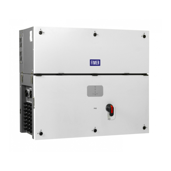
Solar Inverter
PVS-100/120-TL "B2 Version"
Quick Installation Guide
In addition to what is explained in this quick installation guide, the safety and installation information provided in the product manual must be read and
followed. The technical documentation for the product is available at the website.
The device must be used in the manner described in the manual. If this is not the case the safety devices guaranteed by the inverter might be
ineffective.
Advertisement
Table of Contents

Related Manuals for Fimer PVS-100-TL B2


Summary of Contents for Fimer PVS-100-TL B2
- Page 1 Solar Inverter PVS-100/120-TL “B2 Version” Quick Installation Guide In addition to what is explained in this quick installation guide, the safety and installation information provided in the product manual must be read and followed. The technical documentation for the product is available at the website. The device must be used in the manner described in the manual.
- Page 2 For more detailed information regarding proper installation and use of this product, refer to the product manual located at www.fimer.com. ATTENTION –...
-
Page 3: Table Of Contents
Table of Content 1. Reference number index 1.1 Inverter external view 1.2 PVS-100/120-TL ; B2 1.3 PVS-100/120-TL ; B2 ; S2 1.4 PVS-100/120-TL ; B2 ; S(X or Y) 1.5 PVS-100/120-TL ; B2 ; S(X or Y)2 1.6 Communication board 2. - Page 4 11.6 Multifunction Relay connection (ALARM and AUX) 11.7 Demand Response Mode 0 (AS/NZS 4777.2) 12. Description of LED panel 13. Commissioning 13.1 Commissioning via FIMER Installer for Solar Inverters mobile APP 13.2 Commissioning via Web User Interface 14. Technical data 14.1 Technical data table PVS-100-TL 14.2 Technical data table PVS-100-TL (SX, SX2, SY, SY2 Models)
-
Page 5: Reference Number Index
1. Reference number index Inverter external view Inverter external view Power module Multifunction relay connector (ALARM) Wiring box RS-485 120Ohm resistance switch (service only) Mounting bracket RS-485 120Ohm resistance switch Handles RS-485 connector (RJ45) (Service only) Cover quarter cam locks Remote ON/OFF terminal block Wiring box front cover RS-485 line terminal block... -
Page 6: Inverter External View
1.1 Inverter external view... -
Page 7: Pvs-100/120-Tl ; B2
PVS-100_120-TL_B2 1.2 PVS-100/120-TL ; B2 PVS-100_120-TL_B2 PVS-100_120-TL_B2_S2 Power module PVS-100/120-TL ; B2 PVS-100_120-TL_B2 PVS-100_120-TL_B2_S2 Wiring box with internal cover PVS-100/120-TL ; B2 Wiring box without internal cover PVS-100/120-TL ; B2... -
Page 8: Pvs-100/120-Tl ; B2 ; S2
PVS-100_120-TL_B2_S2 1.3 PVS-100/120-TL ; B2 ; S2 PVS-100_120-TL_B2_S2 PVS-100_120-TL_B2_S2 Power module PVS-100/120-TL ; B2 ; S2 PVS-100_120-TL_B2 PVS-100_120-TL_B2_S2 Wiring box with internal cover PVS-100/120-TL ; B2 ; S2 Wiring box without internal cover PVS-100/120-TL ; B2 ; S2... -
Page 9: Pvs-100/120-Tl ; B2 ; S(X Or Y)
PVS-100_120-TL_B2_S(X-Y) 1.4 PVS-100/120-TL ; B2 ; S(X or Y) PVS-100_120-TL_B2 PVS-100_120-TL_B2_S(X-Y) Power module PVS-100/120-TL ; B2 ; S(X or Y) PVS-100_120-TL_B2_S(X-Y) PVS-100_120-TL_B2_S(X-Y) Wiring box with internal cover PVS-100/120-TL ; B2 ; S(X or Y) Wiring box without internal cover PVS-100/120-TL ; B2 ; S(X or Y) -
Page 10: Pvs-100/120-Tl ; B2 ; S(X Or
PVS-100_120-TL_B2_S(X-Y)2 1.5 PVS-100/120-TL ; B2 ; S(X or Y)2 PVS-100_120-TL_B2 PVS-100_120-TL_B2_S(X-Y)2 Power module PVS-100/120-TL ; B2 ; S(X or Y)2 PVS-100_120-TL_B2_S(X-Y)2 PVS-100_120-TL_B2_S(X-Y)2 Wiring box with internal cover PVS-100/120-TL ; B2 ; S(X or Y)2 Wiring box without internal cover PVS-100/120-TL ; B2 ; S(X or Y)2... -
Page 11: Communication Board
1.6 Communication board... -
Page 12: Labels And Symbols
The Communication Identification label (applied on the wiring box) is divided in two separate parts by a dashed line; take the bottom part and apply it on the plant documentation. (FIMER recommend to create a plant map and apply the Communication Identification label on it). - Page 13 In the manual and/or in some cases on the equipment, the danger or hazard zones are indicated with signs, labels, symbols or icons. Always refer to instruction manual ATTENTION- Important safety information WARNING - Hazardous voltage Hot surfaces Risk of electric shock.The discharge time (quantified in the figure by the number XX) of the stored energy after de- energizing of the Inverter from both DC side and AC side.
-
Page 14: Models And Range Of Equipment
3. Models and range of equipment NOTE – The choice of the inverter model must be made by a qualified technician who knows about the installation conditions, the devices that will be installed outside the inverter and possible integration with an existing system. 3.1 Bracket model Model Number Description... - Page 15 P/N’s. Refer to instruction provided together with kits for a proper installation and/or configuration. NOTE – Refer to the “PVS-100_120 GROUNDING KIT” and “PVS-100_120 PRE-CHARGE BOARD KIT“ quick installation guide for further information (available at www.fimer.com).
-
Page 16: Lifting And Transport
Risk of injury due to the heavy weight of the equipment! FIMER usually stores and protects individual components by suitable means to make their transport and subsequent handling easier. Nonetheless, as a rule, it is necessary to turn to the experience of specialised staff to take charge of loading and unloading components. - Page 17 It is required to use one of the following lifting methods to move the equipment during installation or maintenance phases. ATTENTION – Pay attention to completely tight the thread of the handles or eye-bolts. Vertical lifting (handles) Horizontal lifting (handles) Vertical lifting (eyebolts and lifting balancer) Horizontal lifting (eyebolts and lifting balancer)
- Page 18 ATTENTION – Always consider the center of gravity of the enclosures while lifting. Center of gravity (power module) Center of gravity (wiring box) ATTENTION – In case of manual lifting it’s suggested to use a support plan (e.g. a table) to place the equipment during the lifiting operation, to allow the change of hands position.
-
Page 19: List Of Supplied Components
5. List of supplied components Available components for wiring box Q.ty ALARM and AUX relay (33) and RS485 (38) connectors (pre-installed on communication and control board (28)) Remote ON/OFF connector (37) pre-installed on communication board (28) Two-hole gasket for M25 signal cable glands (12) and cap 2 + 2 Key tool for front covers quarter cam-lock (05) M8x16 hex bolt + M8 serrated lock washers to clamp the earth cable on the protective... -
Page 20: Choice Of Installation Location
In case of opening when the unit is wet, avoid any water infiltration inside the unit, either in WB or PM. • All installations over 6500’ (2,000 meters) must be assessed by FIMER Technical Sales to determine the proper datasheet derating. -
Page 21: Installation Of Multiple Units
• Respect minimum distances from objects around the inverter that could prevent the inverter installation and restrict or block the air flow. minimum clearance distances depends from multiple factor: Ventilation flow on the rear side of the inverter. Depending of the support where the inverter is installed it changes the upper (A) required free space: if the inverter is installed on a support without any openings (e.g. -
Page 22: Wireless Signal Environmental Checks
• The installation of two inverters positioned back to back is also permitted on a structure which must be composed of a 2 or 3 frame supports (refer to “Mounting with a support bracket” chapter). In this case the minimum recommended distance between the units in order to avoid the use of an air deflector is 30cm. -
Page 23: Mounting Instructions
ATTENTION – Staff authorized to carry out the installation must be specialized and experienced in PV plant installation and specifically PV inverters installation. FIMER can provide training on the product to provide suitable knowledge for the installation. ATTENTION – The installation must be performed by qualified installers and/or licensed electricians in accordance with the existing regulations in the country of installation. -
Page 24: Assembly The Inverter To The Bracket
• Attach the bracket (03) to the support with at least 6 attachment screws (shown in YELLOW) or at least 6 frame fixing bracket • In case of use of “frame fixing brackets” (see picture below for frame mounting (shown in BLUE). as example) it will be possible to fix the bracket to the frame structure without drill any additional holes. -
Page 25: Opening The Power Module Box Cover
7.3 Opening the power module box cover • Lift the power module up to the bracket (03) and over the wiring box (using the handles (04) or M8 eyebolts) and insert • Using the key tool provided with the PVS installation kit content the heads of two rear attachment pins (13) (placed on the rear in the wiring box package, open the three cover quarter cam part of the power module) into the slots... -
Page 26: Interface Cables Connection
7.5 Interface cables connection Last operation (before proceed with the wiring and connections of external AC and DC sources) is to connect the interface connectors that allow the power and the communication connection between the power module (01) and the wiring box (02). -
Page 27: Routing The Cable To The Inverter
8. Routing the cable to the inverter The cable routing have to be done in order to avoid water dripping to the: • AC panel cable glands (11) (56) • DC input quick fit connectors (16) • DC input cable glands (18) •... -
Page 28: Grid Output Connection (Ac Side)
9.1 Characteristics and sizing of the protective grounding cable FIMER inverters must be earthed via the connection points marked with the protective earth symbol and using a cable with an appropriate conductor cross-section for the maximum ground fault current that the generating system might experience. -
Page 29: Characteristics And Sizing Of The Line Cable
9.3 Characteristics and sizing of the line cable Depending of the type of the AC panel it’s possible to use single conductors cables or a multipolar cable: • Single-core AC panel (11) configuration have 4xM40 cable glands (62) for the ”N” neutral, “R”, “S”, “T” phases and a M25 cable gland (23) for the earth cable. - Page 30 Follow the procedure below to route all the requested cables: ATTENTION – The installation must be performed by qualified installers and/or licensed electricians in accordance with the existing regulations in the country of installation and in accordance of all safety rules for performing electrical works.
- Page 31 AC line connection • Pass the AC cables through the single core cable glands (62) or multicore cable gland (63) on the AC panel. The lenght of phase cables on the internal side of wiring box need to be about 300 mm (cable lug included). •...
-
Page 32: Input Connection (Dc)
10. Input connection (DC) WARNING – Check absence of any leakage to ground in the PV generator. WARNING – If input strings are paralleled, they must have the same installation conditions (number of panel sets, panel type, orientation and tilt). WARNING –... - Page 33 MPPT 1 MPPT 1 MPPT 1 MPPT 1 – – Independent channel configuration (default configuration) MPPT 2 MPPT 2 – MPPT 2 MPPT 2 The independent configuration of the input channels (MPPT) is set by factory. This means that the parallel bar (supplied) must not be installed on the parallel MPPT connection points (31), and that the software setting “Independent channel mode”...
-
Page 34: Connection Of Inputs
10.1.3 Connection of inputs To carry out the connections, the cables must be passed through the DC cable glands (18). Connection of DC cables is made on the DC input connection busbar (17). The bolts on the DC input connection busbar (17) accepts cable lugs as per the following table: DC input cable Cable diameter range 19 - 28 mm... -
Page 35: Input Connection On -S(X Or Y) And S(X Or Y)2 Models
PVS-100_120-TL_B2_S(X-Y) 10.2 Input connection on -S(X or Y) and The correct sizing of the (19) positive side and (20) negative side (-SX2, SY2 wiring box model) string fuses to be used to S(X or Y)2 models protect from “return currents” is very important because it can considerably limit the risk of fire and damage to the PV generator. - Page 36 • Increase in the Isc on the basis of the high temperature of the PV module • Thermal derating of the fuse • Maximum return current of the PV modules installed Fimer can supply fuse kits of different values; these kits could be ordered separately. NOTE – For effective calculation taking real installation conditions into account, refer to the documents supplied by the protection fuse manufacturer.
- Page 37 A configuration program that can help to correctly size the photovoltaic system is available on the Fimer website (http://stringsizer. fimer.com). • Re-install the DC protective shield (60) by using the M5 screws NOTE –...
- Page 38 the selected MPPTs ( 4 MPPTs with 3 strings + 2 MPPT with 4 stings). Connect all the strings required by the system, always checking the seal of the connectors.
-
Page 39: Connection Of The Communication And Control Signals
Terminal Name Terminal Reference Description Multifunction relay connector (ALARM terminal block) RS-485 FIMER service 120Ohm termination resistance switch (FIMER service only) RS-485 line 120Ohm termination resistance switch RS-485 connector (RJ45) (FIMER Service only) (*) Remote ON/OFF terminal block (*) RS-485 line terminal block... -
Page 40: Connections To The Communication And Control Board
Please refer to Aurora Vision documents can be used for the input or for the output of the line connecting available on FIMER website for further information how to multiple inverters in a daisy-chain. get an Aurora Vision account for remotely monitoring and managing the installed solar assets. -
Page 41: Serial Communication Connection (Rs485)
(Modbus/RTU SUNSPEC compliant). inverter itself (master mode). This will allow the inverter to serve as a logger for FIMER The RS-485 serial communication line is available on the accessories. communication and control board (28) with two terminal blocks •... -
Page 42: Multifunction Relay Connection (Alarm And Aux)
(being connected between the NC NOTE – AS4777: If DRM0 support is specified, the inverter terminal and the common contact C). may only be used in conjunction with a the FIMER DRM0 Interface. NOTE – Visit http://solar.fimer.com for more information on the DRM0 interface. -
Page 43: Description Of Led Panel
Indicates that the inverter has detected an anomaly. This type of problem is highlighted in the Web User Interface and FIMER Installer for Solar Inverters APP. The “GFI” (ground fault) LED indicates that the inverter has detected a ground fault in the DC side photovoltaic generator. - Page 44 Pre-commissioning phase (first start-up of inverter) The commissioning of the inverter must be completed through the Installation wizard steps (Web User Interface) or using the FIMER Installer for Solar Inverters mobile APP Initial configuration failure The inverter is in locked state due to a failure in the initial configuration of the equipment, such as the standard...
-
Page 45: Commissioning
13.1 Commissioning via FIMER Installer for Solar Inverters mobile APP FIMER Installer for Solar Inverters APP is available for Android mobile devices with an Android version of 6.0.1 or greater (for iOS mobile devices will be implemented soon) and could be downloaded and installed from Play Store. -
Page 46: Commissioning Via Web User Interface
To address any problems that may occur during the initial stages of operation of the system and to ensure the inverter remains fully functional, you are advised to check for any firmware updates in the download area of the website at https://registration.solar.fimer.com (instructions for registering on the website and updating the firmware are given on the product manual). -
Page 47: Technical Data
14. Technical data 14.1 Technical data table PVS-100-TL (Standard, S2) PVS-100 Wiring Box version Standard, S2 Input side Absolute maximum input voltage (Vmax,abs) 1000 V Start-up input voltage (Vstart) 420 V (400…500 V) Operating input voltage range (Vdcmin...Vdcmax) 360…1000 V Rated input voltage (Vdcr) 620 V Rated input power (Pdcr) - Page 48 7. Only in IT-system (an AC SPD reconfiguration is needed) 8. Hereby, Power-One Italy S.p.A. (A Member of the FIMER Group) declares that the radio equipments (radio module combined with the inverter), to which this user manual refers, are in compliance with the Directive 2014/53/EU. The full text of the EU Declaration of Conformity is available at the following internet address: www.fimer.com...
-
Page 49: Technical Data Table Pvs-100-Tl (Sx, Sx2, Sy, Sy2 Models)
14.2 Technical data table PVS-100-TL (SX, SX2, SY, SY2 Models) PVS-100 Wiring Box version SX, SX2, SY, SY2 Input side Absolute maximum input voltage (Vmax,abs) 1000 V Start-up input voltage (Vstart) 420 V (400…500 V) Operating input voltage range (Vdcmin...Vdcmax) 360…1000 V Rated input voltage (Vdcr) 620 V... - Page 50 Allow to connect the negative input pole to ground 1. Maximum number of opening 5 under overloading 2. Please refer to the document “String inverters – Product manual appendix” available at www.fimer.com for information on the quick-fit connector brand and model used in the inverter 3.
-
Page 51: Technical Data Table Pvs-120-Tl
14.3 Technical data table PVS-120-TL (Standard, S2) PVS-120 Wiring Box version Standard, S2 Input side Absolute maximum input voltage (Vmax,abs) 1000 V Start-up input voltage (Vstart) 420 V (400…500 V) Operating input voltage range (Vdcmin...Vdcmax) 360…1000 V Rated input voltage (Vdcr) 620 V Rated input power (Pdcr) 123000 W... - Page 52 7. Only in IT-system (an AC SPD reconfiguration is needed) 8. Hereby, Power-One Italy S.p.A. (A Member of the FIMER Group) declares that the radio equipments (radio module combined with the inverter), to which this user manual refers, are in compliance with the Directive 2014/53/EU. The full text of the EU Declaration of Conformity is available at the following internet address: www.fimer.com...
-
Page 53: Technical Data Table Pvs-120-Tl (Sx, Sx2, Sy, Sy2 Models)
14.4 Technical data table PVS-120-TL (SX, SX2, SY, SY2 Models) PVS-120 Wiring Box version SX, SX2, SY, SY2 Input side Absolute maximum input voltage (Vmax,abs) 1000 V Start-up input voltage (Vstart) 420 V (400…500 V) Operating input voltage range (Vdcmin...Vdcmax) 360…1000 V Rated input voltage (Vdcr) 620 V... - Page 54 7. Only in IT-system (an AC SPD reconfiguration is needed) 8. Hereby, Power-One Italy S.p.A. (A Member of the FIMER Group) declares that the radio equipments (radio module combined with the inverter), to which this user manual refers, are in compliance with the Directive 2014/53/EU. The full text of the EU Declaration of Conformity is available at the following internet address: www.fimer.com...
-
Page 55: Tightening Torques
14.5 Tightening torques Component Single core AC cable gland (62) M40 8 Nm Multi core AC cable gland (63) M63 100 Nm PE cable gland (23) M25 7.5 Nm Signal cable gland (12) M25 7.5 Nm AC connection busbar (21) M10 bolts 25 Nm DC input connection busbar (17) M10 bolts 25 Nm... - Page 56 ENGLISH ITALIANO DEUTSCH ESPAÑOL FRANÇAIS The symbol of the crossed-out wheeled bin Il simbolo del contenitore di spazzatura Mit dem Symbol der ausgekreuzten Mülltonne El símbolo del contenedor de basura tachado Le symbole de poubelle interdite identifie les identifies electrical and electronic equipment su ruote barrato, accompagnato da una werden Elektro-...
- Page 57 ČESKY ΕΛΛΗΝΙΚΆ POLSKI SLOVENČINA SLOVENŠČINA Symbol přeškrtnuté popelnice na kolečkách Το σύμβολο με τον διαγεγραμμένο τροχήλατο Symbol przekreślonego kosza na śmierci Symbol preškrtnutej odpadkovej nádoby na Simbol prečrtanega koša za smeti na kolesih označuje elektrické a elektronické zařízení κάδο προσδιορίζει ηλεκτρικό και ηλεκτρονικό na kółkach na sprzęcie elektrycznym i kolieskach označuje elektrické...
- Page 58 With regard to purchase orders, the therein. Any reproduction, disclosure to third representative or visit: agreed particulars shall prevail. FIMER does parties or utilization of its contents – in whole not accept any responsibility whatsoever for or in parts – is forbidden without prior written fimer.com...
Need help?
Do you have a question about the PVS-100-TL B2 and is the answer not in the manual?
Questions and answers