Table of Contents
Advertisement
Quick Links
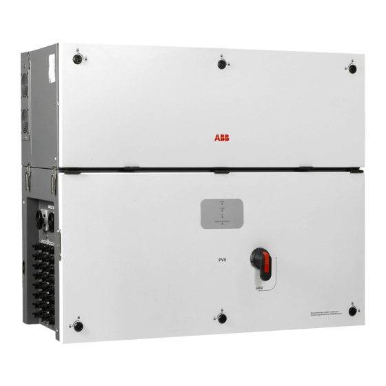
Solar Inverter
PVS-175-TL "A.2 Version"
Quick Installation Guide
In addition to what is explained in this quick installation guide, the safety and installation information provided in the product manual must be read and
followed. The technical documentation for the product is available at the website.
The device must be used in the manner described in the manual. If this is not the case the safety devices guaranteed by the inverter might be
ineffective.
Advertisement
Table of Contents

Related Manuals for Fimer PVS-175-TL


Summary of Contents for Fimer PVS-175-TL
- Page 1 Solar Inverter PVS-175-TL “A.2 Version” Quick Installation Guide In addition to what is explained in this quick installation guide, the safety and installation information provided in the product manual must be read and followed. The technical documentation for the product is available at the website.
- Page 2 For more detailed information regarding proper installation and use of this product, refer to the product manual located at www.fimer.com. ATTENTION –...
-
Page 3: Table Of Contents
Table of Content 1. Reference number index 1.1 Inverter external view 1.2 PVS-175-TL - External sides view 1.3 PVS-175-TL - Power module Internal view 1.4 PVS-175-TL - Wiring box Internal view 1.5 Communication board 2. Labels and Symbols 3. Models and range of equipment 3.1 Bracket model... - Page 4 11.6 Multifunction Relay connection (ALARM and AUX) 11.7 Demand Response Mode 0 (AS/NZS 4777.2) 12. Description of LED panel 13. Commissioning 13.1 Commissioning via FIMER Installer for Solar Inverters mobile APP 13.2 Commissioning via Web User Interface 14. Characteristics and technical data 14.1 Technical data 14.2 Tightening torques...
-
Page 5: Reference Number Index
AC interface connection point Phases cable glands Interface signal connectors (male) Protective earth cable gland Interface protective earth point FIMER RS485 service Ethernet connector (RJ45) (service Signal cable glands only) RS485 FIMER service 120Ohm termination res. (service RS485 Service connector... -
Page 6: Inverter External View
1.1 Inverter external view... -
Page 7: Pvs-175-Tl - External Sides View
1.2 PVS-175-TL - External sides view 1.3 PVS-175-TL - Power module Internal view... -
Page 8: Pvs-175-Tl - Wiring Box Internal View
1.4 PVS-175-TL - Wiring box Internal view... -
Page 9: Communication Board
1.5 Communication board... -
Page 10: Labels And Symbols
The Communication Identification label (applied on the wiring box) is divided in two separate parts by a dashed line; take the bottom part and apply it on the plant documentation. (FIMER recommend to create a plant map and apply the Communication Identification label on it). - Page 11 In the manual and/or in some cases on the equipment, the danger or hazard zones are indicated with signs, labels, symbols or icons. Always refer to instruction manual ATTENTION- Important safety information WARNING - Hazardous voltage Hot surfaces Risk of electric shock.The discharge time (quantified in the figure by the number XX) of the stored energy after de- energizing of the Inverter from both DC side and AC side.
-
Page 12: Models And Range Of Equipment
The choice of the inverter model must be made by a qualified technician who knows about the installation conditions, the devices that will be installed outside the inverter and possible integration with an existing system. 3.1 Bracket model Model Number Description PVS-175-TL-BRACKET Bracket allowing both vertical and horizontal installation. 3.2 Power Module models Model Number Description... -
Page 13: Lifting And Transport
Risk of injury due to the heavy weight of the equipment! FIMER usually stores and protects individual components by suitable means to make their transport and subsequent handling easier. Nonetheless, as a rule, it is necessary to turn to the experience of specialised staff to take charge of loading and unloading components. - Page 14 It is required to use one of the following lifting methods to move the equipment during installation or maintenance phases. ATTENTION – Pay attention to completely tight the thread of the handles or eye-bolts. Vertical lifting (handles) Horizontal lifting (handles) Vertical lifting (eyebolts and lifting balancer) Horizontal lifting (eyebolts and lifting balancer)
- Page 15 ATTENTION – Always consider the center of gravity of the enclosures while lifting. Center of gravity (power module) Center of gravity (wiring box) ATTENTION – In case of manual lifting it’s suggested to use a support plan (e.g. a table) to place the equipment during the lifiting operation, to allow the change of hands position.
-
Page 16: List Of Supplied Components
5. List of supplied components Available components for wiring box Connector for connection of the configurable relay (41) and aux relay (41) (pre-installed on communication board (26)) Connector for connecting the Remote ON/OFF (42) signal and RS485 (43) (pre-installed on communication board (26)) Two-hole gasket (6mm Ø) for PG21 service cable glands (13) and cap 2 + 2... -
Page 17: Choice Of Installation Location
(for example: the type of surface around the inverter, the general properties of the room, etc.) and the quality of the electricity supply. • All installations over 6500’ (2,000 meters) must be assessed by FIMER Technical Sales to determine the proper datasheet derating. -
Page 18: Installation Of Multiple Units
The minimum clearance distances depends from multiple factor: • Ventilation flow on the top side of the inverter. The upper (A) minimum required free space must be 25 • Possible flooding or damage during grass cutting. It changes the bottom (B) required free space: If the inverter is installed in a place where there are risks of flooding or there is need to cut the grass growing underneath the unit, the bottom (B) minimum... -
Page 19: Wireless Signal Environmental Checks
• The installation of two inverters positioned back to back is also permitted on a structure which must be composed of a 2 or 3 frame supports (refer to “Mounting with a support bracket” chapter). In this case the minimum recommended distance between the units in order to avoid the use of an air deflector is 30cm. -
Page 20: Mounting Instructions
ATTENTION – Staff authorized to carry out the installation must be specialized and experienced in PV plant installation and specifically PV inverters installation. FIMER can provide training on the product to provide suitable knowledge for the installation. ATTENTION – The installation must be performed by qualified installers and/or licensed electricians in accordance with the existing regulations in the country of installation. -
Page 21: Assembly The Inverter To The Bracket
7.2 Assembly the Inverter to the bracket • Attach the bracket (03) to the support with at least 6 attachment screws (shown in YELLOW) or at least 6 frame fixing bracket ATTENTION – Handling installation operations for frame mounting (shown in BLUE). shall be performed only by using the special tools and Wall mounting minimum fixing points accessories provided with “PVS-175 Installation Kit”... -
Page 22: Opening The Wiring Box Cover
• Lift the power module up to the bracket (03) and over the • Fasten all of the four side closures (latches) (16) as shown in wiring box (using the handles (04) or M8 eyebolts) and insert the pictures. the heads of two rear attachment pins (17) (placed on the rear part of the power module) into the slots on the bracket (03). -
Page 23: Final Fastening Operations
• Open the Wiring box cover (07) and use the cover support • Remove the three M5 screws from the DC surge arrester plate brackets (15) to lock the cover (07) in open position. (21). • Rotate the DC surge arrester plate (21) as shown in the picture below. -
Page 24: Opening The Power Module Box Cover
7.6 Connection of the AC interface cables • Insert the DC cable duct (22) previously removed to the DC surge arrester plate (21).Tighten the two side screws The AC interface cable lugs (31) (RST phases, PE and MID (supplied) with a tightening torque of 5 Nm, to avoid the tilting BULK) are situated into his cable housing on the top side of of the bottom part of the inverter. -
Page 25: Connection Of The Interface Signal Connectors
7.8 Connection of the DC interface cables The DC interface cables (33) are situated into left side of Power module and they are divided in two group. ATTENTION – The cable lug must be installed with a tightening torque of 3 Nm. ATTENTION –... -
Page 26: Routing The Cable To The Inverter
• Pass the DC interface cables (33) into the wiring box using the • Connect all DC interface cables (33) to the related DC dedicated opening for DC cables (30) as shown in the picture interface faston connectors (29) located in the DC surge arrester plate (21). -
Page 27: Grid Output Connection (Ac Side)
9.1 Characteristics and sizing of the protective grounding cable FIMER inverters must be earthed via the connection points marked with the protective earth symbol and using a cable with an appropriate conductor cross-section for the maximum ground fault current that the generating system might experience. -
Page 28: Characteristics And Sizing Of The Line Cable
The ground connection can be made using the Protective integrated in FIMER inverters, it is not necessary to install earth point (int.) (28), Protective earth point (ext.) (10) or both a type B ground fault switch. - Page 29 AC line connection • Pass the AC cables through the cable glands (11) on the AC panel. The lenght of phase cables on the internal side of wiring box need to be about 300 mm (cable lug included). • Fix the R, S and T cable lugs to the AC connection busbars (27), paying attention to the correspondence of the phases with the labels, using the washers and the M10 nuts pre- installed on the busbar as shown in the following diagram:...
-
Page 30: Input Connection (Dc)
10. Input connection (DC) WARNING – Comply with the maximum input current relating to the quick-fit connectors as indicated in the technical data. WARNING – The reverse polarity can cause severe damage and electric arc hazards! In case of reverse input strings do not disconnect them while under load and do not turn the DC disconnect switches (19) to OFF position. - Page 31 A configuration program that can help to correctly size the photovoltaic system is available on the FIMER website (http://stringsizer.fimer.com/).
-
Page 32: Connection Of The Communication And Control Signals
Ethernet connector 1 (RJ45) USB connector CR2032 Backup battery (*) The RS-485 connector (RJ45) (FIMER Service only) (37) and the signal R1 on the Remote ON/OFF terminal block (42) are used to bring the signals on the external RS-485 Service connector (14). -
Page 33: Connections To The Communication And Control Board
Aurora Vision remote functionalities. ATTENTION – Please refer to Aurora Vision documents available on FIMER website for further information how to get an Aurora Vision account for remotely monitoring and managing the installed solar assets. -
Page 34: Serial Communication Connection (Rs485)
The RS485 port can either be used for connecting supported accessories (like weather station): in this case data from accessories will be logged and transferred to the cloud by inverter itself (master mode). This will allow the inverter to serve as a logger for FIMER accessories. -
Page 35: Remote Control Connection
11.5 Remote control connection Different types of devices (light, sound, etc.) can be connected to the relay, provided they comply with the following requirements: The connection and disconnection of the inverter to and from the grid can be controlled through an external control. The function must be enabled via web server user interface. -
Page 36: Description Of Led Panel
Indicates that the inverter has detected an anomaly. This type of problem is highlighted in the Web User Interface and FIMER Installer for Solar Inverters APP. The “GFI” (ground fault) LED indicates that the inverter has detected a ground fault in the DC side photovoltaic generator. - Page 37 Pre-commissioning phase (first start-up of inverter) The commissioning of the inverter must be completed through the Installation wizard steps (Web User Interface) or using the FIMER Installer for Solar Inverters mobile APP Initial configuration failure The inverter is in locked state due to a failure in the initial configuration of the equipment, such as the standard...
-
Page 38: Commissioning
13.1 Commissioning via FIMER Installer for Solar Inverters mobile APP FIMER Installer for Solar Inverters APP is available for Android mobile devices with an Android version of 6.0.1 or greater (for iOS mobile devices will be implemented soon) and could be downloaded and installed from Play Store. -
Page 39: Commissioning Via Web User Interface
NOTE – For more details about commissioning and any other functionalities of the Installer for Solar Inverters mobile APP please contact FIMER customer support. 13.2 Commissioning via Web User Interface Commissioning could be carried out via wireless connection to the inverter’s Web User Interface. Initial setup of the system must therefore be carried out via a tablet, notebook or smartphone with a wireless connection. -
Page 40: Characteristics And Technical Data
14. Characteristics and technical data 14.1 Technical data PVS-175-TL Input Absolute maximum DC input voltage (Vmax,abs) 1500 V Start-up input voltage (Vstart) 750 V (650 - 1000 V) Input operating interval (Vdcmin...Vdcmax) 600 - 1500V Rated DC input voltage (Vdcr) - Page 41 The AC voltage and frequency range may vary depending on specific country grid standard Hereby, Power-One Italy S.p.A. (A Member of the FIMER Group) declares that the radio equipments (radio module combined with the inverter), to which this user manual refers, are in compliance with the Directive 2014/53/EU. The full text of the EU Declaration of Conformity is available at the following internet address: www.fimer.com.
-
Page 42: Tightening Torques
14.2 Tightening torques Component Single core AC cable gland (11) M40 5 Nm PE cable gland (12) M32 5 Nm Multi core AC cable gland (11) M63 100 Nm Signal cable gland (13) PG16 5 Nm Signal cable gland (13) PG21 7.5 Nm AC connection busbar (27) M10 bolts 25 Nm... - Page 44 ENGLISH ITALIANO DEUTSCH ESPAÑOL FRANÇAIS The symbol of the crossed-out wheeled bin Il simbolo del contenitore di spazzatura Mit dem Symbol der ausgekreuzten Mülltonne El símbolo del contenedor de basura tachado Le symbole de poubelle interdite identifie les identifies electrical and electronic equipment su ruote barrato, accompagnato da una werden Elektro-...
- Page 45 ČESKY ΕΛΛΗΝΙΚΆ POLSKI SLOVENČINA SLOVENŠČINA Symbol přeškrtnuté popelnice na kolečkách Το σύμβολο με τον διαγεγραμμένο τροχήλατο Symbol przekreślonego kosza na śmierci Symbol preškrtnutej odpadkovej nádoby na Simbol prečrtanega koša za smeti na kolesih označuje elektrické a elektronické zařízení κάδο προσδιορίζει ηλεκτρικό και ηλεκτρονικό na kółkach na sprzęcie elektrycznym i kolieskach označuje elektrické...
- Page 46 With regard to purchase orders, the therein. Any reproduction, disclosure to third representative or visit: agreed particulars shall prevail. FIMER does parties or utilization of its contents – in whole not accept any responsibility whatsoever for or in parts – is forbidden without prior written fimer.com...
Need help?
Do you have a question about the PVS-175-TL and is the answer not in the manual?
Questions and answers