Table of Contents
Advertisement
Quick Links
Advertisement
Table of Contents

Related Manuals for Fimer PVS-166-TL US


Summary of Contents for Fimer PVS-166-TL US
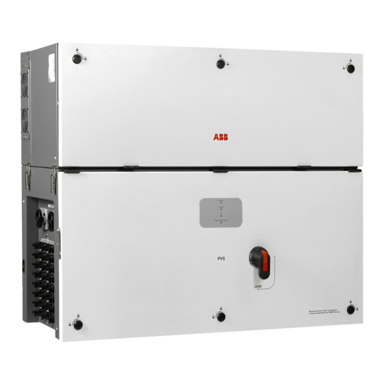
- Page 1 Product Manual PVS-166/175-TL-US (166.5 to 185 kW)
- Page 2 The installer must read this document in its entirety before installing this equipment. Operators are required to read this manual and scrupulously follow the instructions given in it, since FIMER cannot be held responsible for damage caused to people and/or things, or the equipment, if the conditions described below are not observed.
- Page 3 Note: This equipment has been tested and found to comply with the limits for a Class A digital device, pursuant to part 15 of the FCC Rules. These limits are designed to provide reasonable protection against harmful interference when the equipment is operated in a commercial environment. This equipment generates, uses, and can radiate radio frequency energy and, if not installed and used in accordance with the instruction manual, may cause harmful interference to radio communications.
-
Page 4: Table Of Contents
Table of contents 1. Safety and accident prevention 1.1 Safety information and instructions ..................1.2 Symbols and signs ........................1.3 Installation and maintenance safety ..................1.3.1 General safety information ....................1.3.2 Environmental conditions and risks ................. 1.3.3 Electrical and thermal safety .................... 1.3.4 Clothing and protection of personnel ................ - Page 5 3.8 P-Q Capability ........................3.9 Characteristics of a photovoltaic generator ................ 3.10 Description of the equipment ....................3.10.1 Operating diagram (example) ..................3.10.2 Mutual connection of multiple inverters ................3.10.3 Notes on the system sizing..................... 3.11 Functionality and components of the equipment ............. 3.11.1 Highlights .........................
- Page 6 6.1 General conditions ......................... 6.2 Description of the LED panel ....................6.3 User interface .......................... 6.3.1 FIMER Installer for Solar Inverters ..................... 6.3.2 Embedded Web User Interface ..................6.3.3 Aurora Vision Plant Management Platform ..............6.4 Arc fault reset button ......................
- Page 7 7.6.1 Access to the Web User Interface .................. 7.6.2 Web UI - Login page ....................... 7.7 Web User Interface menu structure ..................7.7.1 MAIN menu ........................7.7.2 SETTINGS menu ......................7.7.3 INVERTER LOG menu ..................... 7.7.4 USER menu ........................7.7.5 CONNECTIVITY menu ..................... 7.7.6 SERVICE TOOLS menu ....................
-
Page 8: Safety And Accident Prevention
The operators must read and comply with the technical information and instruction provided in the manual and in the attached documentation. FIMER accepts no liability for failure to comply with the instructions for correct installation and cannot be held responsible for the upstream or downstream equipment. -
Page 9: Symbols And Signs
1.2 Symbols and signs In the manual and/or in some cases on the equipment, the danger or hazard zones are indicated with signs, labels, symbols or icons. Symbol Description Note - General information about product General warning - Important safety information. Indicates a potentially hazardous situation which, if not avoided, could result in death or serious injury. -
Page 10: Installation And Maintenance Safety
1.3 Installation and maintenance safety 1.3.1 General safety information ATTENTION – Do not proceed with installation if the integrity of the equipment is compromised. Do not use the equipment if you find any operating anomalies. ATTENTION – Avoid temporary repairs. All repairs should be carried out using only genuine spare parts, which must be installed in accordance with their intended use. -
Page 11: Electrical And Thermal Safety
ATTENTION – Do not perform insulation or voltage withstand tests on the inverter. WARNING – FIMER inverters must be earthed via the connection points marked with the protective earth symbol and using a cable with an appropriate conductor cross-section for the maximum ground fault current that the generating system might experience. -
Page 12: Residual Risks
1.4 Residual risks ATTENTION – Despite the warnings and safety systems, there are still some residual risks that cannot be eliminated. These risks are listed in the following table with some suggestions to prevent them: Risk analysis and description Suggested remedy Noise pollution due to installation in unsuitable environments or where Reassess the environment or the place of installation. -
Page 13: Introduction And General Information
• use or installation by unqualified persons. FIMER is not responsible for any loss of the equipment, or part of it, which does not take place on the basis of the regulations and laws in force in the country of installation. -
Page 14: Scope And Target Audience
This document contains only the information considered necessary for the use and routine maintenance of the equipment. NOTE – The FIMER solar inverter help desk may be reached at 1-877-261-1374, 6am - 6pm ( Arizona time) Monday-Friday. Excluding major holidays. 2.2.3 Operator and maintenance personnel skills/prerequisites NOTE –... -
Page 15: Application Area, General Conditions
2.3 Application area, general conditions FIMER shall not be liable for any damages whatsoever that may result from incorrect or careless operations. FORBIDDEN – You may not use the equipment for a use that does not conform to that provided for in the field of use. The equipment MUST NOT be used by inexperienced staff, or even experienced staff if carrying out operations on the equipment that fail to comply with the indications in this manual and enclosed documentation. -
Page 16: Characteristics
3. Characteristics 3.1 General conditions A description of the equipment characteristics is provided to identify its main components and specify the technical terminology used in the manual. This chapter contains information about the models, details of the equipment, characteristics and technical data, overall dimensions and equipment identification. -
Page 17: Equipment Identification And Manufacturer
3.2 Equipment identification and manufacturer The labels on the power module and on the wiring box have the Agency marking, main technical data and identification of the equipment and manufacture. The technical data provided in this manual does not substitute the data supplied on the labels affixed to the equipment. -
Page 18: Inverter Identification Label
The “communication identification label” (applied on the wiring box) is divided in two separate parts by a dashed line; take the bottom part and apply it on the plant documentation. FIMER recommend to create a plant map and apply the “communication identification label” on it. -
Page 19: Models And Range Of Equipment
3.3 Models and range of equipment NOTE – The choice of the inverter model must be made by a qualified technician who knows about the installation conditions, the devices that will be installed outside the inverter and possible integration with an existing system. The pieces of equipment which make up the inverter to which this manual is dedicated are: Three-phase power module: •... -
Page 20: Component Reference Designators
Interface signal connector Handles AC interface power cable Cover quarter cam locks Alarm terminal block Side latch RS485 FIMER service 120Ohm termination res. Wiring box front cover DRM0 activation switch LEDs panel RS485 line 120Ohm termination res. AC disconnect switch (-SX2 only) - Page 21 PVS-166/175-TL-US - External sides view PVS-166/175-TL-US Power module- Internal view...
- Page 22 PVS-166/175-TL-US Wiring box- Internal view...
-
Page 23: Characteristics And Technical Data
PVS-166/175-TL-US - Communication board (28) 3.5 Characteristics and technical data 3.5.1 Technical data and types PVS-166-TL US PVS-175-TL US Input side Absolute maximum DC input voltage 1500 V (Vmax,abs) Start-up DC input voltage 750 V (650…1000 V) (Vstart) Operating DC input voltage range (Vdcmin... - Page 24 PVS-166-TL US PVS-175-TL US Maximum input short circuit current for 30 A each MPPT (ISCmax) Number of DC input pairs for each MPPT 2 DC inputs per MPPT DC connection type PV quick fit connector Input protection Type I acc. to UL 1699B with single-MPPT sensing...
-
Page 25: Tightening Torques
PVS-166-TL US PVS-175-TL US Remote inverter FW upgrade via Ethernet/WLAN FW update interface locally/remotely Remote inverter parameter upgrade via Ethernet/ Parameter upgrade WLAN according to SunSpec Modbus protocol Environmental -13...+140°F (-25...+60°C) Operating ambient temperature range with derating above 104°F (40°C) Relative humidity 0...100% condensing... -
Page 26: Overall Dimensions Of The Inverter
3.5.3 Overall dimensions of the inverter The overall dimensions, not including the mounting bracket 03, are expressed in millimeters and inches. 1060 / 41.7 387 / 14.4 1086 / 42.7 419 / 16.5 458 / 18 3.5.4 Overall dimensions of the mounting bracket The dimensions of the wall mounting bracket 03 are expressed in millimeters and inches. -
Page 27: Efficiency Curves
3.6 Efficiency curves Graphs of the efficiency curves of all models of inverter described in this manual are shown below. NOTE – The efficiency curves are linked to technical parameters that are continually being developed and improved and should therefore be considered approximate. 3.6.1 PVS-175-TL-US - Efficiency Vs Nominal Power Rated Output Power (%) 850 Vdc... -
Page 28: Power Derating
3.7 Power derating In order to allow inverter operation in safe thermal and electrical conditions, the unit automatically reduces the value of the power fed into the grid. Power derating may occur due to: • Adverse environmental conditions (thermal derating) •... -
Page 29: P-Q Capability
3.8 P-Q Capability The following represents the maximum P-Q capability of the unit under the specified operating conditions. Q (kVAR) PVS-166 PVS-166-TL-US Ambient temperature up to 40 °C Maximum Active Power 166.5 kW (Pac_max) Maximum Apparent Power 166.5 kVA (Smax) Maximum Reactive Power 111 kVAR (Qmax) -
Page 30: Characteristics Of A Photovoltaic Generator
3.9 Characteristics of a photovoltaic generator A PV generator consists of an assembly of photovoltaic modules that transform solar radiation into DC electrical energy and can be made up of: • Strings: number (X) of PV modules connected in series •... -
Page 31: Description Of The Equipment
PV generator); in order to use it, it is transformed into “AC” alternate current. This conversion, known as inversion from DC to AC, is done in an efficient way by the FIMER inverters, without using any rotary elements, rather only via static electronic systems. -
Page 32: Notes On The System Sizing
IN 10 NOTE – A configuration program that can help to correctly size the photovoltaic system is available on the FIMER website (http://stringsizer.fimer.com). IN 11 ATTENTION – When configuring DC input and during the installation it’s needed to follow... -
Page 33: Functionality And Components Of The Equipment
PV plants by using smart phones, tablets and iPod Touch with IOS and Android operating systems. 4. FIMER Ability™ for solar plants - Energy Viewer is an easy to use mobile application allowing solar plant owners to remotely monitor all the energy flows and the performance of their own pv plants, with and without an energy storage system installed. -
Page 34: Configurable Relays
NOTE – Please contact the FIMER tecnichal support for getting your own Plant Portfolio Manager account (mainly for installers and plant administrators). Please get your Plant Viewer, Plant Viewer for Mobile or Energy Viewer by accessing the website www. auroravision.net and click on “Register with Plant Viewer” button (mainly for site owners). -
Page 35: Overvoltage Surge Arrester Monitoring(-Sx/Sx2 Models Only)
Aurora Vision Plant Management platform is the FIMER cloud solution allowing customer to remotely monitor and manage its own solar plants. Please refer to http://www.fimer. com or contact FIMER technical support for further information on how getting an Aurora Vision account... -
Page 36: Topographic Diagram Of The Equipment
With the inverters connected over Ethernet daisy chain and with an available internet connection it will be always possible, via Aurora Vision Cloud, to upgrade remotely the firmware of the inverters. In order to improve the communication services and allow reaching of all the inverters in the chain also in presence of fault it is recommended to create a ring shape layout by connecting both the first and the last inverters of the chain to the local Ethernet switch (as shown in the picture). -
Page 38: Safety Devices
3.14 Safety devices 3.14.1 Anti-Islanding In the event of a local grid outage by the electricity company, or when the equipment is switched off for maintenance operations, the inverter must be physically disconnected to ensure the protection of the people working on the grid, in accordance with the relevant national laws and regulations. To prevent possible islanding, the inverter is equipped with an automatic safety disconnection system called “Anti-Islanding”. -
Page 39: Lifting And Transport
4. Lifting and transport 4.1 General conditions NOTE – Some recommendation apply only to large size product or multiple small size product packaging. 4.1.1 Transport and handling Transport of the equipment, especially by road, must be carried out with means for protecting the components (in particular, the electronic components) from violent shocks, humidity, vibration, etc. -
Page 40: Unpacking And Checking
Risk of injury due to the heavy weight of the equipment! FIMER usually stores and protects individual components by suitable means to make their transport and subsequent handling easier. Nonetheless, as a rule, it is necessary to turn to the experience of specialised staff to take charge of loading and unloading components. - Page 41 M8. Hole for Eyebolts UNI2947 (not supplied) M8. Kit of handles (04) (to be ordered) *lifting balancer must be 20 cm longer (per side) than the lifted device. ATTENTION – Always consider the center of gravity of the enclosures while lifting. Center of gravity (wiring box) Center of gravity (power module)
-
Page 42: List Of Supplied Components
ATTENTION – In case of manual lifting it’s suggested to use a support plan (e.g. a table) to place the equipment during the lifiting operation, to allow the change of hands position. 4.1.6 List of supplied components Available component on the wiring box (02) package: Component Quantity Multifunction and aux relay (33) connector (pre-installed on... -
Page 43: Kit Of Recommended Spare Parts
Available component on the bracket 03 package: Component Quantity M8 screws with washers for mechanically securing the half-brackets M6 screws for mechanically securing the wiring box to the bracket 4.1.7 Kit of recommended spare parts Code Description Quantity Kit of handles (04) Key tool for front cover quarter cam- lock PVS-175 INSTALLATION KIT... -
Page 44: Installation
5. Installation 5.1 Installation warnings ATTENTION – The inverter must be correctly installed, in a suitable location, to operate properly and safely. ATTENTION – Staff authorised to carry out the installation must be specialised and experienced in this job. They must also have received suitable training on equipment of this type and must know and understand applicable NEC requirements and any local codes for photovoltaic systems. -
Page 45: Installation Planning
2.0 A Sensitivity FIMER declares that the FIMER transformerless inverters, in terms of their construction, do not inject continuous earth fault currents and therefore there is no requirement that the differential protection installed downstream of the inverter be type B in accordance with IEC 60755 / A 2. -
Page 46: Characteristics And Sizing Of The Line Cable
The model of connectors installed on your inverter must be matched by the same model of the respective corresponding parts to be used (check the corresponding part on the manufacturer’s website or with FIMER). ATTENTION – Using mating parts that are not compliant with the quick fit connector models on the inverter could cause serious damage to the unit and lead to invalidation of the warranty. - Page 47 Type Manufacturer Model and PN Conductor cross section Ø cable gland PV-KBT4-EVO 2 32.0087P0001-UR 4mm² (11AWG) - 6mm² (9AWG) 4.7-6.4 mm / 0,18-0.25” Male Stäubli 32.0089P0001-UR 4mm² (11AWG) - 6mm² (9AWG) 6.4 - 8.4 mm / 0.25-0.33” 32.0093P0001-UR 10mm² (7AWG) 6.4 - 8.4 mm / 0.25-0.33”...
-
Page 48: Installation Site And Position
5.3 Installation site and position 5.3.1 General recommendation on installation position • See characteristics and technical data paragraph to check the required environmental conditions (protection rating, temperature, humidity, altitude, etc.). • The installation location shall be easily accessible. • Installation of the unit in a location exposed to direct sunlight is NOT acceptable (add awning in case of direct sunlight installation). - Page 49 • Do not install any object (e.g. AC or DC cables) that could be damaged by overheating from outgoing hot air flow from top and side fan sections (ΔT= +15 °C compared to ambient temperature). In case of this kind of installation needs, please evaluate the installation of a proper air deflector. Always respect the minimum distances required.
-
Page 50: Installation Of Multiple Units
• 3. Cables bending radius. The minimum required free space for proper ventilation of the unit (near side fans) cannot be under 15 cm on the right side and 30cm on the left side. Sides (C) minimum required free space may depends from conduit or cable type (cable dimension, bending radius, etc..). -
Page 51: Wireless Signal Environmental Checks
5.3.5 Wireless signal environmental checks The inverter can be commissioned and monitored using the wireless communication channel. The WLAN board of the inverter uses radio waves to transmit and receive data, it is therefore important to assess this factor in order to have optimal installation. Walls in reinforced concrete and surfaces covered with metal (doors, shutters, etc.) might significantly reduce the reach of the device which even in optimal conditions, is approximately 40 metres in free space. -
Page 52: Installations Of Ip65 Protection Covers For Wiring Box Openings (Long Term Installation)
5.4 Installations of IP65 protection covers for wiring box openings (long term installation) Never leave the power module 01 or the wiring box 02 disassembled on the field. In case is necessary to install the wiring box 02 only, protection covers for wiring box openings (long term installation) kit is available as accessory options. -
Page 53: Mounting Instruction
5.5 Mounting Instruction • Position the bracket (03) perfectly level on the support and use it as drilling template. Consider the overall dimensions of the 5.5.1 Bracket (03) assembly power module (01) and the wiring box (02). • Assemble the two side bracket pieces •... -
Page 54: Assembly Of Inverter To The Bracket
NOTE – In case of use of “frame fixing brackets” (see picture example) it will be possible to fix the bracket to the frame structure without drilling any additional holes. • Remove handle or other lifting device (if used) • Lift the power module (01) up to the bracket (03) and over the wiring box (02), using the handles (04) or the M8 eyebolts. -
Page 55: Opening The Wiring Box Cover
ATTENTION – During this 5.5.3 Opening the Wiring box installation phase special cover attention to not damage the gaskets on the AC and DC coupling system. • Using the key tool (provided with the kit DC gaskets contained in the wiring box package), open the three cover quarter cam locks (05) following the proper rotation as shown in the related silkscreens on the Wiring box cover... -
Page 56: Final Fastening Operations
5.5.4 Final fastening operations To reach the two junction screws (20) and complete the power module (01) and wiring box (02) mating, the DC surge arrester plate (21) have to be opened as follow: • Remove the cable duct (54) from the DC surge arrester plate (21). -
Page 57: Connection Of The Ac Interface Power Cables
5.5.6 Connection of the AC interface power cables The AC interface power cable (32) (RST phases, PE and MID BULK) are situated into the cable housing on the top side of wiring box (02). • Open the power module cover (50). •... -
Page 58: Connection Of The Interface Signal Connectors
The DC interface cables (18) and AFD • Install the protective earth cable lug to the protection earth point interface cable (26) interface cables (59) are situated into left side situated on the internal bottom side of of Power module (01). power module (01). - Page 59 • Pass the DC interface cables (18) into the • Connect the two AFD interface cables to same dedicated opening used for the AFD the related ARC fault connectors (19) interface cables. located in the DC surge arrester plate. • Connect all DC interface cables (18) to the related DC interface connection point connectors located in the DC surge arrester plate (21).
-
Page 60: Routing The Cable To Th E Inverter
PVS-175 5.6 Routing the cable to th e inverter Cables should be routed in a manner which prevents water from dripping on the DC input connectors (16). 20-30 cm Min. of Especially when coming from the top, the DC cables must be routed in order to create a loop: in this straight way the water that flows on the cables will be drained. -
Page 61: Grid Output Connection (Ac Side)
5.7 Grid output connection (AC side) WARNING – To avoid risks of electrical shock, all wiring operations must be carried out with the disconnect switch downstream of the inverter (grid side) opened and applying LOTO procedure on it. Be careful not to change round one of the phases with neutral! ATTENTION –... - Page 62 • Attach the protective earth cable lug to the protection earth connection point (55) using the washers and bolt pre-installed on the M10 stud: 1 = cable lug 2 = flat washer 3 = spring washer 4 = M10 nut •...
-
Page 63: Checking The Correct Polarity Of The Strings And Input Connection (Dc)
5.8 Checking the correct polarity of the strings and Input connection (DC) HOT SURFACE – Do not place objects of any kind on the inverter during operation! HOT SURFACE – Do not touch the heatsink while the inverter is operating!Some parts may be very hot and cause burns. - Page 64 The input connectors are divided into 12 • Connect all the strings required by the MPPTs consisting of 2 pairs of quick fit system, always checking the seal of the connectors (17). connectors. Each DC disconnect switch (16) disconnects a group of 3 MPPTs. •...
-
Page 65: Connection Of The Communication And Control Signals
Memory board RS485 line communication board (*) The RS-485 connector (RJ45) (FIMER Service only) (37) and the signal R1 on the Remote ON/ OFF terminal block (38) are used to bring the signals on the external connector RS-485&Rem.ON/ OFF (Service only) (56). -
Page 66: Connections To The Communication And Control Board
5.9.3 Ethernet connection The Ethernet connection allows a direct data transfer to the FIMER server for monitoring purpose. When the inverter will be powered on, network parameters are automatically set and the inverter starts the transmission of telemetry data to the Aurora Vision® CLOUD platform. - Page 67 Internet connection is required to use all the Aurora Vision remote functionalities. NOTE – Please refer to Aurora Vision documents available on FIMER website for further information how to get an Aurora Vision account for remotely monitoring and managing the...
-
Page 68: Serial Communication Connection (Rs485 - Slave Mode)
5.9.4 Serial communication connection (RS485 - Slave mode) ATTENTION – Please note that automatic settings of network parameters at turning on, embedded logging capability, automatic logger-free transferring of data to Aurora Vision Cloud and remote firmware update are provided over TCP/IP (Ethernet and/or Wi-fi) bus only. - Page 69 The RS485 line can be used to set up a line of communication which, when connected to a monitoring device, enables the operation of the photovoltaic system to be kept under control. Depending on the device used monitoring can be local or remote. TO MONITORING SYSTEM 485+...
- Page 70 (36) in the OFF position. RS485 RJ45 external connector for FIMER Service operation The inverter has an second RS485 communication lines (that could be access using the external RJ45 connector (56)) working as Slave to be used by FIMER Service personnel only. This communication...
-
Page 71: Serial Communication Connection (Rs485 - Master Mode)
(master mode). This will allow the inverter to serve as a logger for FIMER accessories. For more information on connecting the accessories to the RS485 terminal block, refer to the accessory product manual or contact FIMER customer support. -
Page 72: Multifunction Relay Connection (Alarm And Aux)
5.9.7 Multifunction Relay connection (ALARM and AUX) The inverter is equipped with 2 multifunction relay terminal blocks (33) with configurable activation. It can be connected with normally open contact (being connected between the NO terminal and the common ALARM contact C) and with normally closed contact (being connected between the NC terminal and the common N.C. -
Page 73: Instruments
- there are doubts or contradictions between your experience, the manual and/or other operators. FIMER cannot be held responsible for damage to the equipment or the operator if it is the result of lack of knowledge, insufficient qualifications or lack of training. -
Page 74: User Interface
• Plant Viewer: single web page for casual user. • Plant Viewer for Mobile: mobile application for plant monitoring. • FIMER Ability™ for solar plants - Energy Viewer: mobile application for plant monitoring. • Kiosk view: single HTML5 page for public visualization of plant data. -
Page 75: Monitoring And Data Transmission
• Mobile app and webserver • Data transmission on the dedicated RS-485 serial line. The data can be collected by a PC or a data logger equipped with an RS-485 port. Contact the FIMER support service with any queries about device compatibility. -
Page 76: Operation
7. Operation 7.1 General conditions Before checking the operation of the equipment, it is necessary to have a thorough knowledge of the Instruments chapter 6 and the functions that have been enabled in the installation process. The equipment operates automatically without the aid of an operator; the operating state should be controlled through the equipment’s instrumentation. -
Page 77: Commissioning Via Installer For Solar Inverters Mobile App
Recommended as alternative method for performing single inverter commissioning. 7.2.1 Commissioning via Installer for Solar Inverters mobile APP “Installer for Solar Inverters” is the new advanced FIMER mobile APP allows to simplify commissioning, parameter settings and troubleshooting of FIMER string multi-inverters in large scale solar plants. - Page 78 same inverters family; no more than 40 • Enter the “Product Key” and “Enter” to inverters by time can be configured confirm. together. As an alternative of QR code scanning, claiming process can be executed by selecting manually the SSIDs associated to the Wi-Fi networks generated by each inverter to commission and inserting Product key when requested:...
- Page 79 • Tap the “Commissioning” button. • Select the country standard and the configuration of the input channels and confirm the setting by clicking “DONE”. • Enter the IP Settings(DHCP or Static), Network SSID and password. • The image shows successful Tap on “Connect”...
- Page 80 For any other specific settings of parameters of single inverters please refer to “Description of the Web User Interface” chapter. • After the commissioning via FIMER Installer for Solar Inverters APP is completed, the inverter changes the behaviour of the “Power” and “Alarm” LEDs , in relation of the input voltage value:...
-
Page 81: Commissioning Via Web Ui - Wireless Connection
NOTE – In case of need, product key can be recovered by Aurora Vision Cloud of by calling FIMER technical support. COMMISSIONING PROCEDURE - WIRELESS CONNECTED • Open an internet browser (recommended browser: Chrome versions from v.55, Firefox versions from v.50) and enter the pre-set IP address 192.168.117.1 to access the Web User Interface. - Page 82 The required information during the procedure are: STEP 1 - Administrator/User login credentials • Set the Administrator account user and password (minimum 8 character for password): Administrator account can open and view the contents of photovoltaic site. Additionally, they can make changes to inverter settings.
- Page 83 NOTE – Host Name associated each FIMER inverter is structured as indicated below: FIMER-logger ID.LOCAL where logger ID stands for the MAC address indicated on the “Communication identification lable” applied on the inverter. The parameters related to the customer wireless network (set on the router) that must be known and set during this step are: •...
- Page 84 Once the inverter is connected to the customer wireless network, a new message will confirm that the connection is acquired. The message provides the IP Address assigned by the home wireless network router to the inverter that can be used each time you want to access the Web User Interface, with the inverter connected to the home wireless network.
- Page 85 A notification will confirm that the wizard is completed. • After the commissioning via FIMER Installer for Solar Inverters APP is completed, the inverter changes the behaviour of the “Power” and “Alarm” LEDs , in relation of the input voltage value:...
-
Page 86: Leds Behaviour
In addition it is possible to use the mobile App ‘FIMER ability Energy Viewer for solar plants’ and the FIMER Web portal Aurora Vision (please refer to product manual for further details) to monitor all production data. - Page 87 The buffer battery is low and the inverter does not maintain the time setting Pre-commissioning phase (first start-up of inverter) The commissioning of the inverter must be completed through the Installation wizard steps (Web User Interface) or using the FIMER Installer for Solar Inverters mobile APP Initial configuration failure...
-
Page 88: Arc Fault Detection
7.4 Arc fault detection The Arc Fault Circuit Protection required by NFPA 70 Article 690.11 is provided by the inverter. The AFD performs a self-test when the system is started: • If the self-test results are OK, the inverter will continue to AC grid connection. •... - Page 89 in the inverter. - Power factor as function of output power (Watt/Cosφ Settings: Cosφ(P)): In this mode, the inverter reduces the power factor (cos-phi) as a function of the output power at a given operating point. The 4 points of the default curve, where you can set the % of Pmax values and related cos- phi, can be modified using the internal Webserver.
-
Page 90: Connection To Web User Interface
NOTE – In case of need, product key can be recovered by Aurora Vision Cloud of by calling FIMER technical support. • Open an internet browser (reccomended browser: Chrome versions from v.55, Firefox versions from v.50) and enter the pre-set IP address 192.168.117.1 to access the login page. -
Page 91: Web Ui - Login Page
7.6.2 Web UI - Login page After you have connected the device to the inverter and you access to the login page, login with the username and password created during the commissioning phase. NOTE – User and password are CASE SENSITIVE. NOTE –... -
Page 92: Main Menu
7.7.1 MAIN menu In the MAIN section it’s possible to access the following sub-menus: DASHBOARD STATUS SUMMARY DASHBOARD In the Dashboard sub-menu you can view the main information related the status and the production information of the inverter and photovoltaic plant and alarm/warning active events. STATUS SUMMARY In the Status Summary sub-menu you can view the detailed information related the status and the production information of the system. - Page 93 Change the activation voltage only if really necessary and to set it to the correct value: the photovoltaic generator sizing tool available on the FIMER website will indicate whether Vstart needs to be changed and what value have to be set.
- Page 94 NOTE – Do not change these parameters if not requested by the grid operator. INVERTER PARAMETERS > Ramp Control (Only visible and editable with Admin Plus privileges) In the Ramp Control sub-menu you can config the parameter related to the active power ramp up at the start-up and after a grid fault event.
- Page 95 - Alarm ALL - no-latch The relay is activated (status: switched) whenever an error (code INVERTER RUN Exxx) or warnings related to grid parameters out of range (Warning N.C. – codes W003, W004, W005, W006, W007) are present on the Relay State: Idle N.O.
- Page 96 Vin > Vstart - Crepuscular N.C. The relay is activated (status: switched) as soon as the inverter input Relay State: Switched N.O. voltage exceeds the activation voltage set. The relay is in its rest position when the input voltage drops below 70% Vin <...
-
Page 97: Inverter Log Menu
To access on the Web User Interface with the “Admin Plus” user privileges it’s required to enter a security token that can be obtained by registering on the website https://registration.solar.fimer.com. Refer to the dedicated section on this topic in the manual. -
Page 98: Connectivity Menu
7.7.5 CONNECTIVITY menu In the CONNECTIVITY section it’s possible to access the following sub-menus: WLAN RS485 DEBUG SETTINGS MODBUS In the LAN sub-menu it’s possible to view the status and change the daisy chain configuration of the two ethernet ports (40) (41) of the inverter. - Daisy chain configuration: DHCP or Static: By selecting the DHCP function (default setup) the router will automatically assign a dynamic IP address to the... - Page 99 In case of connection to channel 2 (“Station Mode”), it will be required to enter the wireless network parameters (set on the router) and follow the subsequent procedure: - IP Selection Mode: DHCP or Static: By selecting the DHCP function (default setup) the router will automatically assign a dynamic IP address to the inverter whenever it tries to connect to the user network.
- Page 100 - “Device Acquisition”: Enables polling and logging of data from FIMER supported accessories directly connected with the RS485 port like VSN800 Weather Station, digital environmental sensors, meters (MASTER operating mode). DEBUG SETTINGS In the Debug Settings sub-menu it’s possible to enable or disable the Debugging access for FIMER Service purposes.
- Page 101 Select device type in the “Add device” field. It’s possible to choose between “Generic SunSpec Device” and “FIMER B23/24 Power Meter”, then click the [+] button to add the new device. Change the SLAVE ID / “NAME” if necessary and save...
-
Page 102: Service Tools Menu
By updating in local mode, the firmware have to be selected and uploaded from local folder of the devices used to access to the web server. The latest firmware version is available from the download area of the website www.fimer.com or from https://registration.solar.fimer.com Click on “FW SELECT”... - Page 103 CONNECTIVITY CHECK In the Connectivity Check sub-menu it’s possible to carry out connectivity tests of the wireless network connection, ethernet connection, connection to Aurora Vision and firmware upgrade servers. At the end of the test it will be reported the detail of the results. COUNTRY STANDARD By accessing to the Country Standard sub-menu you can modify the grid standard within 24 hours while the...
-
Page 104: Information Menu
DATE AND TIME In the Date and Time sub-menu it’s possible to sets the date, time and time zone. The inverter will propose these fields when the time protocol is available). When it’s not possible for the inverter to detect the time protocol, these fields have to be manually entered. -
Page 105: Maintenance
8. Maintenance 8.1 General conditions Routine and periodic maintenance operations must only be carried out by specialized staff with knowledge of how to perform these tasks. WARNING – Some inverter parts may be subject to voltages that could be hazardous for the operator. -
Page 106: Operator And Maintenance Personnel Skills/Prerequisites
8.2.1 Operator and maintenance personnel skills/prerequisites NOTE – Personnel in charge of using and maintaining the equipment must be skilled for the described tasks and must reliably demonstrate their capacity to correctly interpret what is described in the manual. ATTENTION – For safety reasons, the installation must be performed by qualified installers and/or licensed electricians in accordance with the existing regulations in the country of installation and in accordance of all safety rules for performing electrical works. -
Page 107: Inverter Total De-Energization And Safe Access Procedure
8.2.4 Inverter total de-energization and safe access procedure... - Page 108 HOT SURFACE – When the device has just been switched off, it may have hot parts as a result of overheating of the heated surfaces (e.g.: transformers, accumulators, coils, etc.) so be careful where you touch. WARNING – Some inverter parts may be subject to voltages that could be hazardous for the operator.
- Page 109 Function Remote OFF 1, 2, 4, 6, 8 Not used RS485 for FIMER 3, 5 Service operation • Connect the modified RJ45 cable to the external RJ45 connector (56) to perform a soft shut-down of the inverter. The connection of the cable will causes the interruption of the operation of the inverter, i.e.
- Page 110 5. Operations on External AC switches The diagram below represents a possible arrangement of the PV plant. Depending on the design choices made by the developer of the plant some of the devices could not be present. Identify the external AC switch(es) in the plant with the support of the plant manager. PVS-175-TL-US Unit under service Power module...
- Page 111 switch (if present) PVS-175-TL-US Power module Wiring box PV Arrays Internal Internal DC switch AC switch (if present) 6. Operations on External DC switches (if present) External AC External DC switch switch (if present) NOTE – In case of absence of External DC disconnect device skip this step. The diagram below represents a possible arrangement of the PV plant.
- Page 112 Internal Internal DC switch AC switch Wiring box (if present) PV Arrays Internal Internal DC switch AC switch External AC External DC switch (if present) switch (if present) External AC External DC switch switch (if present) Operations on internal AC disconnect Switch (09) (only -SX2 models) NOTE –...
- Page 113 DC switch AC switch (if present) External AC External DC switch switch (if present) PVS-175-TL-US Power module Wiring box • Affix designated lock preventing operation onto all DC disconnect switches (16), affixing designated PV Arrays Internal Internal tags (LOTO procedure). DC switch AC switch (if present)
- Page 114 WARNING – The discharge time of the stored energy is indicated on the regulatory label. 11. Voltage absence test on DC side (wiring box) ATTENTION – Before to approach the below operations all the steps from1 to 9 included must be successfully completed. •...
- Page 115 Check sequence: Check sequence: Check sequence: Positive to ground (PE) Negative to ground (PE) Positive to negative First point Second point First point Second point First point Second point CH1(+) CH1(-) CH1(+) CH1(-) CH2(+) CH2(-) CH2(+) CH2(-) CH3(+) CH3(-) CH3(+) CH3(-) CH4(+) CH4(-)
- Page 116 R (L1) Check First Second sequence point point S (L2) Check #1 R (L1) Check #2 S (L2) Check #3 T (L3) Check #4 R (L1) S (L2) T (L3) Check #5 S (L2) T (L3) Check #6 T (L3) R (L1) 13.
- Page 117 14. Voltage absence test on bulk capacitors (Power Module) ATTENTION – Before to approach the below operations all the steps from 1 to 12 included must be successfully completed. • Access to the power module box (01) by opening the power module front cover (50). •...
- Page 118 BULK 16. Check list to be filled prior the access to the inverter • Purpose of the checklist is to verify that all the operations mentioned in the procedure have been carried out. The checklist below must be attached to the intervention report. Check STATUS (√...
-
Page 119: Routine Maintenance
ATTENTION – Maintenance operations shall be performed only by qualified personnel or FIMER personnel (under a servicing contract). The maintenance schedule may vary depending on the environmental conditions of the installation. Routine maintenance Annual visual •... -
Page 120: Replacing Of The Side Fan Section
WARNING – The following operation must be carried out wearing the appropriate insulating composite gloves class 0 EN60903 (1000Vac-1500Vdc) resistant to electric arc class 2 (7kA) EN61482-1-2 in combination with protective overglove in leather EN420 – EN388. ATTENTION – When replacing the external fan sections it’s strictly recommended to clean the fins of internal heatsink using compressed air (blowing air from top and the side to the rear of the inverter). -
Page 121: Replacing Of The Top Fan Section
8.4.2 Replacing of the top fan section Procedure for replacing the side fan sections: • Open the DC disconnect switches (16). • Open any AC disconnect switch downstream of the inverter or the AC disconnect switch (09) (only on -SX2 model). ATTENTION –... -
Page 122: Replacing The Internal Fan Section
8.4.3 Replacing the internal fan section WARNING – Some inverter parts may be subject to voltages that could be hazardous for the operator. Before performing any work on the inverter, refer to “Inverter total de- energization and safe access” chapter on this manual to know all the necessary step to safely operate on the inverter. -
Page 123: Replacing The Dc Surge Arrester Cartridge
8.5 Replacing the DC surge arrester cartridge WARNING – Some inverter parts may be subject to voltages that could be hazardous for the operator. Before performing any work on the inverter, refer to “Inverter total de- energization and safe access” chapter on this manual to know all the necessary step to safely operate on the inverter. -
Page 124: Replacing The Ac Surge Arrester Cartridge
8.6 Replacing the AC surge arrester cartridge WARNING – Some inverter parts may be subject to voltages that could be hazardous for the operator. Before performing any work on the inverter, refer to “Inverter total de- energization and safe access” chapter on this manual to know all the necessary step to safely operate on the inverter. -
Page 125: Replacement Of The Memory Board
8.7 Replacement of the MEMORY board WARNING – Some inverter parts may be subject to voltages that could be hazardous for the operator. Before performing any work on the inverter, refer to “Inverter total de- energization and safe access” chapter on this manual to know all the necessary step to safely operate on the inverter. -
Page 126: Replacement Of The Comm Rs485 Board
8.8 Replacement of the COMM RS485 board WARNING – Some inverter parts may be subject to voltages that could be hazardous for the operator. Before performing any work on the inverter, refer to “Inverter total de- energization and safe access” chapter on this manual to know all the necessary step to safely operate on the inverter. -
Page 127: Replacement Of The Buffer Battery
8.9 Replacement of the buffer battery WARNING – Some inverter parts may be subject to voltages that could be hazardous for the operator. Before performing any work on the inverter, refer to “Inverter total de- energization and safe access” chapter on this manual to know all the necessary step to safely operate on the inverter. -
Page 128: Procedure For Dismantling The Equipment
8.10 Procedure for dismantling the equipment WARNING – The dismantling operations must be carried out with the equipment disconnected from any voltage sources. Refer to “Inverter total de-energization and safe access” chapter on this manual to know all the necessary step to safely operate on the inverter. - Page 129 • Remove the power module (01) following the indications for the mounting procedure in the “Mounting with a support bracket - Assembly the Inverter to the bracket” chapter in the reverse order and the indication for lifting methods in “Type of lifting” chapter. ATTENTION –...
-
Page 130: Troubleshooting
8.11 Troubleshooting ATTENTION – Operations on the inverter to identify and address any faults may only be performed by the installer or by qualified personnel. 8.11.1 Web User Interface and wireless communication troubleshooting The following table gives a list of main and most common errors or problems relating to the wireless communication between inverter and user devices. - Page 131 Problem Possible causes Solution The inverter might not be correctly powered (for example, if the Access to the Web User Interface only when the inverter is switched off at night, inverter is correctly powered. the Web User Interface cannot be accessed).
-
Page 132: Alarm Messages Of The Inverter
8.11.2 Alarm Messages of the Inverter In order to understand and resolve warning (Wxxx) or error (Exxx) signals that appear in the Event or Dashboard section of the Web User Interface follow the table given in the following paragraph. The equipment can notify errors/warnings in the Event or Dashboard section of the Web User Interface only if the input voltage is greater than the Vdcmin voltage (POWER Led flashing or lit;... - Page 133 - Error code - Error message Name of Alarm and Cause Solution - LED status • Check the grid voltage on the inverter. - Should it be absent, check for absence of grid voltage on the supply point. - If, on the other hand, the voltage tends to rise (when the inverter is connected) there is high line or grid Parameters of grid voltage outside range: impedance.
- Page 134 - Error code - Error message Name of Alarm and Cause Solution - LED status • Check that the date/time are set correctly and, if they are not, set them. Subsequently arrange to completely switch off the - W012 Battery Low: inverter (on both AC and DC) and wait a few minutes.
- Page 135 - Error code - Error message Name of Alarm and Cause Solution - LED status • Once the error occurs, the inverter tries to return to normal operation. Connection to the grid unsuccessful If the problem persists after a number of attempts to - W046 The alarm is logged when a Missing grid or Input UV error connect the inverter, switch the inverter off and then on...
- Page 136 - Error code - Error message Name of Alarm and Cause Solution - LED status • Error inside the inverter and cannot be checked - E005 Communication error inside the inverter: externally. - Internal error The alarm occurs when there are communication problems - If the problem persists (once the inverter has been between the control devices inside the inverter.
- Page 137 - Error code - Error message Name of Alarm and Cause Solution - LED status Long wait for “Inverter” regime to start up: - If the error signal occurs sporadically, it may be due Error internal to inverter relating to start-up time for the to causes external to the inverter (limited irradiation DC-AC circuit regime (Inverter) and so limited power availability from the PV...
- Page 138 - Error code - Error message Name of Alarm and Cause Solution - LED status • Error inside the inverter and cannot be checked - E024 externally. Error inside the inverter: - Internal error - If the problem persists (once the inverter has been Error inside the inverter switched off and back on again), contact customer Yellow LED...
- Page 139 - Error code - Error message Name of Alarm and Cause Solution - LED status • Error inside the inverter and cannot be checked - E034 externally. “IGBT” circuitry not ready: - IGBT not ready - If the problem persists (once the inverter has been Error inside the inverter switched off and back on again), contact customer Yellow LED...
-
Page 140: Power Limitation Messages
- Error code - Error message Name of Alarm and Cause Solution - LED status • Error inside the inverter and cannot be checked - E054 Arc Fault board communication error: externally. - AFDD comm. Error on the RS485 serial communication detected - If the problem persists (once the inverter has been Fault between the inverter and the AFDD board. -
Page 141: Registration Website" And "Admin Plus Token
The security token obtained enables access also to the advanced “Installer” mode present on the configuration software for inverters. The configuration software can be downloaded in a specific section of the website https://registration.solar.fimer.com Stage 3 - Request for the security token •... - Page 142 • Access section dedicated to requesting the security token • Choose the inverter model from the drop-down list and insert Serial Number and Week of Production of the inverter which were obtained previously (Stage • Click on icon to request the security token.
-
Page 143: Verification Of Ground Leakage
8.13 Verification of ground leakage In the presence of anomalies or report of ground fault (where provided), there may be a ground leakage from the PV generator (DC side). To check this, measure the voltage between the positive pole and ground and between the negative pole (of the PV generator) and ground using a voltmeter whose input accepts a voltage sufficient for the dimensions of the photovoltaic generator. -
Page 144: Behaviour Of A System With Leakage
8.13.2 Behaviour of a system with leakage If the voltage measured between one of the two poles and ground does not tend to 0V and stabilizes on a value, there is a ground leakage from the PV generator. Example: When the measurement is made between positive pole and ground, a voltage of 200V is measured. -
Page 145: Measuring The Isolation Resistance Of The Pv Generator
8.14 Measuring the isolation resistance of the PV generator WARNING – The operator must always use the personal protective equipment (PPE) required by the laws of the country of destination and whatever is provided by their employer. To measure the isolation resistance of the PV generator compared to ground , the two poles of the PV generator must be short-circuited (using a suitable sized switch). -
Page 146: Storage And Dismantling
8.15.2 Dismantling, decommissioning and disposal FIMER is not responsible for any loss of the equipment, or part of it, which does not take place on the basis of the regulations and laws in force in the country of installation. -
Page 147: Attachments
(if present) must allow responses to the inverter over existing TCP connections. Direction Service/Port Protocol Description For local debugging by FIMER service personnel, the inverter utilizes encrypted ssh/22 SSH. To allow service personnel local access to the inverter. The inverter must be able to resolve domain names, to... -
Page 148: Network Hosts
9.1.2 Network Hosts The inverter will connect to the following hosts. Some servers owned by FIMER, and others are customer or ISP servers. Servers listed as owned by “Customer IT/ISP” must be configured in the inverter using either DHCP or as static network information. - Page 150 With regard to purchase orders, the agreed Any reproduction, disclosure to third parties or representative or visit: particulars shall prevail. FIMER does not accept utilization of its contents – in whole or in parts – is any responsibility whatsoever for potential errors or forbidden without prior written consent of FIMER.
Need help?
Do you have a question about the PVS-166-TL US and is the answer not in the manual?
Questions and answers