Table of Contents
Advertisement
Quick Links
This user's guide describes the operation, use, features, and characteristics of the TLV320AIC3212EVM-
U. This small form factor evaluation module (EVM) is a programmable USB audio device that features the
TLV320AIC3212 Audio Codec.
1
1.1
1.2
2
2.1
2.2
3
3.1
3.2
4
5
6
7
8
9
9.1
9.2
10
1
2
3
4
5
6
7
8
9
10
11
12
13
14
15
16
17
18
Windows is a trademark of Microsoft Corporation.
SLAU435 - March 2012
Submit Documentation Feedback
TLV320AIC3212EVM-U Evaluation Module
...............................................................................................................
.............................................................................................................
.........................................................................................................
....................................................................................
.....................................................................................................
.................................................................................................
...........................................................................................
...................................................................................
.......................................................................................................
.....................................................................................
...............................................................................
.................................................................................................
..............................................................................................................
...........................................................................................................
.....................................................................................
.....................................................................................
...................................................................................................
............................................................................................................
........................................................................................................
.........................................................................................
...........................................................................................................
...............................................................................................
.........................................................................................
.....................................................................................
.....................................................................................
.....................................................................................
................................................................................
..................................................................................................
..................................................................................................
..................................................................................................
..................................................................................................
Copyright © 2012, Texas Instruments Incorporated
Contents
................................................................
List of Figures
.............................................................................
....................................................................
..........................................................
...............................................................
TLV320AIC3212EVM-U Evaluation Module
User's Guide
SLAU435 - March 2012
2
2
2
3
3
4
6
6
7
12
15
23
28
30
32
32
33
35
2
4
5
7
8
9
10
11
12
12
13
13
14
14
15
16
17
18
1
Advertisement
Table of Contents

Related Manuals for Texas Instruments TLV320AIC3212EVM-U


Summary of Contents for Texas Instruments TLV320AIC3212EVM-U
-
Page 1: Table Of Contents
Example Scripts ..................Headphone playback script ..................Microphone recording script ....................Related Documentation List of Figures ................Top view of TLV320AIC3212EVM-U board ......................USB Connection ..............Using Example Configurations in Control Software ......................Main Panel Window ..................Example Configurations Window ............ -
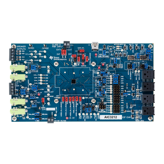
Page 2: Evm Overview
The TLV320AIC3212EVM-U is compatible with Windows™ XP-based personal computers. Introduction The TLV320AIC3212EVM-U is a USB audio device with programmable inputs and outputs, effects, and extensive routing capabilities. It is a simple platform to evaluate the TLV320AIC3212 Audio Codec. Figure 1. Top view of TLV320AIC3212EVM-U board TLV320AIC3212EVM-U Evaluation Module SLAU435 –... -
Page 3: Evm Description And Getting Started
RESET RESET switch Cycles through the applications loaded in the onboard EEPROM. PATCH Cycles through the patches loaded in the onboard EEPROM. USB_RESET USB_RESET SLAU435 – March 2012 TLV320AIC3212EVM-U Evaluation Module Submit Documentation Feedback Copyright © 2012, Texas Instruments Incorporated... -
Page 4: Getting Started
Section 7 for default jumper settings) 2. Download and install the TLV320AIC3212EVM-U Control Software from the EVM product folder. The password for installation is "CC". 3. Connect the TLV320AIC3212EVM to an available USB port. LED lights D1 and D2 should illuminate once the EVM is detected by PC. -
Page 5: Using Example Configurations In Control Software
5. Open AIC3212 Control Software and select a typical headphone playback script, as shown in Figure Figure 3. Using Example Configurations in Control Software SLAU435 – March 2012 TLV320AIC3212EVM-U Evaluation Module Submit Documentation Feedback Copyright © 2012, Texas Instruments Incorporated... -
Page 6: Aic3212 Control Software
3. In that folder, install the Software by double-clicking the “CC.exe” and follow the directions. The installation password is “CC”. 4. Connect TLV320AIC3212EVM-U to PC through USB cable and open up TLV320AIC3212 Control Software. The software will then pop up a window called select EVM to prompt the user to choose the... -
Page 7: Using The Aic3212Evm-U Cs
“EVM status” on the bottom part of the main panel reflects the hardware connection of the EVM. “USB Fs” indicates the current sample rate of the EVM board. SLAU435 – March 2012 TLV320AIC3212EVM-U Evaluation Module Submit Documentation Feedback Copyright © 2012, Texas Instruments Incorporated... -
Page 8: Example Configurations Window
“Example Configuration…” under View. Once the typical configuration is selected, click “ProgramCodec” to download the script into EVM. Figure 5. Example Configurations Window TLV320AIC3212EVM-U Evaluation Module SLAU435 – March 2012 Submit Documentation Feedback Copyright © 2012, Texas Instruments Incorporated... -
Page 9: Tlv320Aic3212 Control Software Command-Line Window
A panel is open • The “Run” button in the command-line interface is pressed • The “Refresh” button on the main panel window is pressed SLAU435 – March 2012 TLV320AIC3212EVM-U Evaluation Module Submit Documentation Feedback Copyright © 2012, Texas Instruments Incorporated... -
Page 10: Decode Window
“Decode” tab on the command-line interface window. The content of the command buffer can be cleared by clicking “Clear” button. TLV320AIC3212EVM-U Evaluation Module SLAU435 – March 2012 Submit Documentation Feedback Copyright © 2012, Texas Instruments Incorporated... -
Page 11: Register Inspector Window
SLAU435 – March 2012 TLV320AIC3212EVM-U Evaluation Module Submit Documentation Feedback Copyright © 2012, Texas Instruments Incorporated... -
Page 12: Pc Board Drawings
The working dimensions of the PCB as shown below are 165mm × 91.4mm (6.5 × 3.6 inches). Figure 9. TLV320AIC3212EVM PCB Top Figure 10. TLV320AIC3212EVM PCB Layer 2 TLV320AIC3212EVM-U Evaluation Module SLAU435 – March 2012 Submit Documentation Feedback Copyright © 2012, Texas Instruments Incorporated... -
Page 13: Tlv320Aic3212Evm Pcb Layer 3
PC Board Drawings www.ti.com Figure 11. TLV320AIC3212EVM PCB Layer 3 Figure 12. TLV320AIC3212EVM PCB Bottom Copper, Reversed SLAU435 – March 2012 TLV320AIC3212EVM-U Evaluation Module Submit Documentation Feedback Copyright © 2012, Texas Instruments Incorporated... -
Page 14: Tlv320Aic3212Evm Pcb Bottom
PC Board Drawings www.ti.com Figure 13. TLV320AIC3212EVM PCB Bottom Figure 14. TLV320AIC3212EVM PCB Drill Pattern TLV320AIC3212EVM-U Evaluation Module SLAU435 – March 2012 Submit Documentation Feedback Copyright © 2012, Texas Instruments Incorporated... -
Page 15: Tlv320Aic3212Evm-U Schematic
TLV320AIC3212EVM-U Schematic www.ti.com TLV320AIC3212EVM-U Schematic The schematic diagram and the top-assembly drawing for the TLV320AIC3212EVM-U is provided as a reference. U2 - TAS1020B USB CONTROLLER AUDIO CONTROL U17 - TLV320AIC3212YZFEVM-U TLV320AIC3212IYZF I2C & SPI CONTROL INTERFACE BALL ASSIGNMENTS I2C & SPI... -
Page 16: Schematic, Sheet 2 Of 8
100K 0.1uF 0.1uF USB RESET PATCH# +3.3VD +3.3VD IOVD 0.1uF 0.1uF RESET~ +3.3VD RESET RESET SN74LVC1G126DBVR 0.1uF Figure 16. Schematic, Sheet 2 of 8 TLV320AIC3212EVM-U Evaluation Module SLAU435 – March 2012 Submit Documentation Feedback Copyright © 2012, Texas Instruments Incorporated... -
Page 17: Schematic, Sheet 3 Of 8
TP57 CURRENT MEASUREMENT VARVD VBAT_ext NO CONNECT TLV320AIC3212YZF +3.3VD +1.8V_CP IOVDD 0.1uF IOVD VARVD 0.1uF 10uF TLV320AIC3212YZF Figure 17. Schematic, Sheet 3 of 8 SLAU435 – March 2012 TLV320AIC3212EVM-U Evaluation Module Submit Documentation Feedback Copyright © 2012, Texas Instruments Incorporated... -
Page 18: Schematic, Sheet 4 Of 8
REC OUT RECM RECR 0.47uF RIGHT IN3R 47uF IN3R_TP 0.47uF IN4L IN4L_TP 0.47uF IN4R IN4R_TP TLV320AIC3212YZF 0.47uF TLV320AIC3212IYZF Figure 18. Schematic, Sheet 4 of 8 TLV320AIC3212EVM-U Evaluation Module SLAU435 – March 2012 Submit Documentation Feedback Copyright © 2012, Texas Instruments Incorporated... - Page 19 SCLK SIDE A GPIO2_BCLK I2S_4 & GPO1_DOUT SPI_SELECT BREAKOUT GPIO1_WCLK CONNECTOR TP21 TLV320AIC3212YZF RESET~ SCL_IOVD SDA_IOVD RESET~ Figure 19. Schematic, Sheet 5 of 8 SLAU435 – March 2012 TLV320AIC3212EVM-U Evaluation Module Submit Documentation Feedback Copyright © 2012, Texas Instruments Incorporated...
- Page 20 Installed Installed Power Down ALL Installed Removed Input/6 Input/12 Removed Installed Input/8 Input/16 Removed Removed Input/2 Input/4 Figure 20. Schematic, Sheet 6 of 8 TLV320AIC3212EVM-U Evaluation Module SLAU435 – March 2012 Submit Documentation Feedback Copyright © 2012, Texas Instruments Incorporated...
- Page 21 +1.8V SRC2_MCLK IOVD IOVD IOVD SRC1_MCLK 0.1uF U15 - 15 0.1uF U16 - 15 SCL_IOVD SDA_IOVD RESET~ Figure 21. Schematic, Sheet 7 of 8 SLAU435 – March 2012 TLV320AIC3212EVM-U Evaluation Module Submit Documentation Feedback Copyright © 2012, Texas Instruments Incorporated...
- Page 22 Empty para to force the bill of materials to a new landscape page Empty para to force the bill of materials to a new landscape page TLV320AIC3212EVM-U Evaluation Module SLAU435 – March 2012 Submit Documentation Feedback Copyright © 2012, Texas Instruments Incorporated...
-
Page 23: Tlv320Aic3212Evm-U Bill Of Materials
OSCILLATOR SMT 3.3V SM77H SERIES 22.5792MHz NU HORIZONS SM7745HSV- PLETRONICS SM7745HSV-22.5792M ROHS 22.5792M OSCILLATOR SMT 3.3V SM77H SERIES 24.576MHz NU HORIZONS SM7745HSV- PLETRONICS SM7745HSV-24.576M ROHS 24.576M SLAU435 – March 2012 TLV320AIC3212EVM-U Evaluation Module Submit Documentation Feedback Copyright © 2012, Texas Instruments Incorporated... - Page 24 CAP SMD1206 CERM 0.047ufd 50V COG 5% ROHS DIGI-KEY 490-1764-1-ND MURATA GRM31M5C1H473JA01L C4, C5 CAP SMD0603 CERM 47PFD 50V 5% COG ROHS DIGI-KEY 490-1419-1 MURATA GRM1885C1H470JA01D TLV320AIC3212EVM-U Evaluation Module SLAU435 – March 2012 Submit Documentation Feedback Copyright © 2012, Texas Instruments Incorporated...
- Page 25 Item REF DES Description Vendor Vendor Part NO. MANU MANU Part NO. FERRITE CHIP, 220 OHMS 2A 100MHZ SMD 0603 ROHS DIGI-KEY 445-1565-1 MPZ1608S221A SLAU435 – March 2012 TLV320AIC3212EVM-U Evaluation Module Submit Documentation Feedback Copyright © 2012, Texas Instruments Incorporated...
- Page 26 ED1516 ON SHORE TECHNOLOGY ED555/4DS 16-28AWG ROHS J6, J11 TERMINAL BLOCK 2PIN 6A/125V GRAY 3.5mm PITCH DIGI-KEY ED1514 ON SHORE TECHNOLOGY ED555/2DS 16-28AWG ROHS TLV320AIC3212EVM-U Evaluation Module SLAU435 – March 2012 Submit Documentation Feedback Copyright © 2012, Texas Instruments Incorporated...
- Page 27 REF DES Description Vendor Vendor Part NO. MANU MANU Part NO. 1001 AS NEEDED SHUNT STANDARD 2POS .200 TIN DIGI-KEY A31698-ND TE CONNECTIVITY 531230-4 SLAU435 – March 2012 TLV320AIC3212EVM-U Evaluation Module Submit Documentation Feedback Copyright © 2012, Texas Instruments Incorporated...
-
Page 28: Default Jumper Positions
Default Jumper Positions www.ti.com Default Jumper Positions Table 3. TLV320AIC3212EVM-U Default Jumper Positions Reference Default Position Description Designator Supply for SRVDD Supply for SLVDD Selection between Record to USB and SRC Record Installed AVDD3_33 Current Measurement Installed HVDD Current Measurement... - Page 29 Default Jumper Positions www.ti.com Table 3. TLV320AIC3212EVM-U Default Jumper Positions (continued) Reference Default Position Description Designator Clock selection for SRC1_MCLK Clock selection for SRC2_MCLK Installed Jumper for MICBIAS_EXT Selection for MCLK1 Open Selection for MCLK2 6 wire I S enable on GPI3...
-
Page 30: Writing Scripts
For example, to write the values 0xAA 0x55 to an I C device with a slave address of 0x30, starting at a register address of 0x03, the user writes: TLV320AIC3212EVM-U Evaluation Module SLAU435 – March 2012 Submit Documentation Feedback Copyright © 2012, Texas Instruments Incorporated... - Page 31 When ready to proceed, the user pushes that button and the script continues. SLAU435 – March 2012 TLV320AIC3212EVM-U Evaluation Module Submit Documentation Feedback Copyright © 2012, Texas Instruments Incorporated...
-
Page 32: Example Scripts
# select page 4 w 30 00 04 # set ASI#1 16 bits, I2S mode w 30 01 00 w 30 0A 00 ######################################### TLV320AIC3212EVM-U Evaluation Module SLAU435 – March 2012 Submit Documentation Feedback Copyright © 2012, Texas Instruments Incorporated... -
Page 33: Microphone Recording Script
PLL Disabled, AOSR = 128, PRB_R1 Primary I2S interface used with WCLK & BCLK as inputs to the device ############################################## ########################################### # Software Reset SLAU435 – March 2012 TLV320AIC3212EVM-U Evaluation Module Submit Documentation Feedback Copyright © 2012, Texas Instruments Incorporated... - Page 34 # Signal processing ########################################### # Select Page 0 w 30 00 00 # Set the ADC PRB Mode to PRB_R1 w 30 3D 01 ########################################### TLV320AIC3212EVM-U Evaluation Module SLAU435 – March 2012 Submit Documentation Feedback Copyright © 2012, Texas Instruments Incorporated...
-
Page 35: Related Documentation
# Power-up ADC Channel w 30 51 C0 # Unmute ADC channel and Fine Gain = 0dB w 30 52 00 ################################################## Related Documentation 1. TLV320AIC3212EVM-U Software SLAU435 – March 2012 TLV320AIC3212EVM-U Evaluation Module Submit Documentation Feedback Copyright © 2012, Texas Instruments Incorporated... - Page 36 Evaluation Board/Kit Important Notice Texas Instruments (TI) provides the enclosed product(s) under the following conditions: This evaluation board/kit is intended for use for ENGINEERING DEVELOPMENT, DEMONSTRATION, OR EVALUATION PURPOSES ONLY and is not considered by TI to be a finished end-product fit for general consumer use. Persons handling the product(s) must have electronics training and observe good engineering practice standards.
- Page 37 IMPORTANT NOTICE Texas Instruments Incorporated and its subsidiaries (TI) reserve the right to make corrections, modifications, enhancements, improvements, and other changes to its products and services at any time and to discontinue any product or service without notice. Customers should obtain the latest relevant information before placing orders and should verify that such information is current and complete.
Need help?
Do you have a question about the TLV320AIC3212EVM-U and is the answer not in the manual?
Questions and answers