Table of Contents
Advertisement
Quick Links
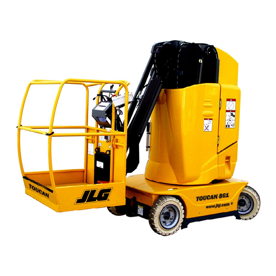
M ODELS
TOUCAN 861
U.S.A.
JLG INDUSTRIES, INC
1 JLG Drive
M cConnellsburg
PA 17 2 3 3 -9 5 3 3
Tél : (171 ) 4 8 5 -5161
Fax : (717 ) 4 8 5 -6 417
Updated : 04-2006
C.E.
JLG Industries,
Kilmartin Place,
Tannochside Park
Uddingston, Scotland G71 5PH
Tel : +4 4 (0 )16 9 8 81 10 0 5
Fax : +4 4 (0 )1 6 9 8 8 1 1 0 5 5
FRANCE
JLG France SAS
Z.I. de Fauillet
BP 2 0 - 474 0 0 TONNEINS
France
Tel : +3 3 5 5 3 8 4 8 5 1 1
Fax : +3 3 5 5 3 7 9 0 6 8 7
English - Service
M A0280-01
Advertisement
Table of Contents

Related Manuals for JLG TOUCAN 861


Summary of Contents for JLG TOUCAN 861
- Page 1 M ODELS TOUCAN 861 U.S.A. C.E. FRANCE JLG INDUSTRIES, INC JLG Industries, JLG France SAS 1 JLG Drive Kilmartin Place, Z.I. de Fauillet M cConnellsburg Tannochside Park BP 2 0 - 474 0 0 TONNEINS PA 17 2 3 3 -9 5 3 3...
- Page 3 Models English Version Toucan 861 N° ___________ MA0280-01 Models Toucan 861 Updated 04-06...
-
Page 4: Table Of Contents
Adjustment of slack chain sensors ----------------------------------------------- 4.5 Adjustment of battery discharge indicator ------------------------------------- 4.6 Adjustment of flashing light pressure sw itches------------------------------- 4.7 Hydraulic adjustments ---------------------------------------------------------------- 4.8 Upper control valve ------------------------------------------------------------------------ 4.8.1 Drive manifold ------------------------------------------------------------------------------- 4.8.2 REMOVAL - INSTALLATION Suit e -------------------------------------------------------------------------------------------- Models Toucan 861 Updated 04-06... - Page 5 Low er control valve ------------------------------------------------------------------- 5.9 Release control valve ----------------------------------------------------------------5.10 Drive manifold -------------------------------------------------------------------------5.11 Upper auxillary manifold ------------------------------------------------------------5.12 Cylinder supply manifolds ----------------------------------------------------------5.13 Mast cylinder -------------------------------------------------------------------------------- 5.13.1 Jib cylinder ----------------------------------------------------------------------------------- 5.13.2 Safety manifold ---------------------------------------------------------------------------- 5.13.3 CONTROLS - MAINTENANCE Models Toucan 861 Updated 04-06...
- Page 6 This page intentionally left blank.
- Page 7 CHAPTER 1 INTRODUCTION Models Toucan 861 Updated 04-06...
- Page 8 We therefore recommend that these repair and maintenance procedures are carried out only by authorized and qualified personnel. Constant improvement make it necessary that JLG reserve the right to make specification and equipment changes without notice. If you have any questions on operating, maintenance procedures, contact your authorized JLG distributor.
- Page 9 Safety instructions contained in the operator's procedure or condition. and safety handbook apply also during operating controls, maintenance and repairs. They do not replace national, state or local work regulations, industry standards or employer's work rules. Models Toucan 861 Updated 04-06...
- Page 10 This page intentionally left blank.
- Page 11 : Safety, Operation Correctness, and Technical Content. All SMCAR's will be reviewed by the responsible Department at JLG. Approved SMCAR's will be distributed in a Service Bulletin immediately and then incorporated in the next scheduled change to the manual. An answer to the SMCAR's, approved or disapproved, will be sent directly to the one submitting the SMCAR.
- Page 12 This page intentionally left blank.
-
Page 13: Platform Characteristics
CHAPTER 2 WORK PLATFORM CHARACTERISTICS Models Toucan 861 Updated 04-06... - Page 14 This page intentionally left blank.
-
Page 15: Description
(left hand side of the mast) is supplied by the hand pump. The energy for the control and power circuits of the work platform is supplied by a 24 Vdc battery. Models Toucan 861 Updated 04-06... -
Page 16: Characteristics - Dimensions - Performances
Pressure 20 µm absolute Ret urn M ast PRESSURES Overall Steering Slew ing raising raising Hydraulic circuit max. pressure (MPa) ELECTRICAL COMPONENTS Pow er of pow er unit mot or 3 kW - 24 Vdc Models Toucan 861 Updated 04-06... - Page 17 (**) times measured with the maximum rated load in the platform (200 kg), the movements were performed from the control panel in the platform. Constant product improvement make it necessary that JLG reserve the right to make specification and equipment changes without notice.
-
Page 18: Identification Of Components
Dump valve manifold Circuit breaker Mast cylinder 5-13-1 Tilt sensor Jib cylinder 5-13-2 Mast switch Steering cylinder Incline sensor Power unit Driving wheel Pressure filter Steering wheel See OP = see Operator's and safety handbook Models Toucan 861 Updated 04-06... - Page 19 HORN MOTOR Supply BATTERY GHARGER BATTERY Battery Filling Pump DISCON- -NECTION FUSE 325A TILT SENSOR 24V DC BATTERY PACK SLOPE SENSORS Flashing Lights PRESSURE SW CHAIN [SW11 ] [SW13] DESCENT ENABLES SLACK [SW12 ] [SW14] Models Toucan 861 Updated 04-06...
- Page 20 This page intentionally left blank.
-
Page 21: Breakdown
CHAPTER 3 BREAKDOWN Models Toucan 861 Updated 04-06... - Page 22 This page intentionally left blank.
-
Page 23: General Procedure
The safety of persons working on and around the work platform must be your prime concern. After repairs, the work platform can only return to service after a thorough functional check. All covers and protections must be installed. Models Toucan 861 Updated 04-06... - Page 24 - a temporisation on start up (to absorb the acceleration at the start of the drive movement): (K3). - memorisation of the sensors opening: (K4). Suppression of 3rd gear availability is signalled by an orange light indicator on the platform control panel. Models Toucan 861 Updated 04-06...
-
Page 25: Troubleshooting
Drive problems. Diag VI : Mast raising problems. Diag VII : Mast lowering problems. Diag VIII : Jib raising problems. Diag IX : Jib lowering problems. Diag X : Slewing problems. Diag XI : Steering problems. Models Toucan 861 Updated 04-06... - Page 26 See page "Diag I-2" Discharge indicator condition Green See page "Diag I-3" Tilt signaled Press on reset sw itch then on enable Pump turns Pump does not turn See page "Diag I-4" See page "Diag I-5" Models Toucan 861 Updated 04-06...
- Page 27 Check the coupling between Broken the motor and the pump. Replace. correct Contact JLG Product Support. Condition Pump contactor Does not stick Check / repair the connection terminal block upper control box - wire # 10 - Measure the voltage at input <...
- Page 28 < 24V Check / repair the cable on battery indicator connector. - wire # 3 - Check position and absence of Incorrect See § 3.3.2. oxydation of contact (see § 3.3.2). correct Replace the battery indicator. Models Toucan 861 Updated 04-06...
-
Page 29: Settings
Check / repair the connector CR1 -see §3.3.2 - Check / Repair the cable - wire # 8 - Check / repair the connections. terminal block and emergency stop switch Check mechanical working order. Replace the emergency stop switch contact. Models Toucan 861 Updated 04-06... - Page 30 / terminal block. Check / repair the connector. See § 3-3-2. Check / repair the cable rep.28, the battery indicator and contact of SW6. Check / repair the connections. Pump does not turn See folowing page Models Toucan 861 Updated 04-06...
- Page 31 < 24V relay K2 / terminal block. coil of K2 - wire # 26 & 11 - Check / repair the wire # 11 relay K2 / terminal block. Check / repair connections. Replace relay K2. Models Toucan 861 Updated 04-06...
- Page 32 Measure the voltage at terminal block < 24V Check / repair the link cable LCB - wire rep.17 - LCB / tilt. Check / repair the block connections. Check / repair the connections of diode D9 or replace D9. Models Toucan 861 Updated 04-06...
- Page 33 Measure voltage at the terminals of one < 24V coils / LCB. of the coils for lowering autorisation. Check / repair the connectors CR1 and CR3 - see § 3.3.2 - See JLG Product Support. Models Toucan 861 Updated 04-06...
- Page 34 Measure the general pressure < 22 Mpa Adjust the general pressure relief valve while the jib is being lowered. or clean the system and/or replace the seals and/or replace the relief valve. 22 Mpa See JLG Product Support. Models Toucan 861 Updated 04-06...
- Page 35 No 3rd gear or 3rd gear does not hold See page "Diag V-1" See page "Diag V-1" State of indicator for sw itching to 2nd gear (during drive). See page "Diag V-2" See page "Diag V-3" Models Toucan 861 Updated 04-06...
- Page 36 Motor brakes stuck and/or not functionning. Important internal leak in the drive manifold, Remove / repair or Contact JLG Product Support. Contact JLG Product Support. 3rd gear ≈ 2nd gear = 1st gear Measure the voltage at coil terminals '' Low speed disable"...
- Page 37 Check / repair CR7 -see § 3.3.2- Check continuity wire # 37 / PC0194 between LCB term. block and CR7. Correct < 20V Measure the voltage at wire # 37 on CR7(2) Replace tilt sensor Contact JLG Product Support. Models Toucan 861 Updated 04-06...
- Page 38 Check the control valve Incorrect (operation). Clean and / or replace the control valve. Correct Contact JLG Product Support. < 24V Check / repair wire # 10 between Measure the voltage at wire # 10 < 24V terminal block & reset.
- Page 39 Remove and inspect the shuttle valve Incorrect Clean and / or located under the emergency control replace the shuttle valve. valve. Correct Check / replace the flow regulator. Check / replace the load holding valve. contact JLG Product Support. Models Toucan 861 Updated 04-06...
- Page 40 Clean and / or replace the seals Check the load holding valve (operation). and/or replace the valve. Correct Contact JLG Product Support. Lowering only if enable is kept depressed Check the check valve on pump outlet for leaks. Incorrect Clean and/or replace the valve.
- Page 41 Battery connections in good condition. The machine is on flat and horizontal ground. Measure the pressure during the movement Low pressure (<8MPa) Normal pressure (8-14MPa) Contact JLG Product Support. Adjust the jib elevation pressure relief valve. Impossible Incorrect Clean and/or replace the seals Remove and inspect the relief valve.
- Page 42 Clean / replace the seals Check the load holding valve (operation). and/or replace the valve. Correct Contact JLG Product Support. Lowering only if enable kept depressed Incorrect Check the check valve on pump outlet for leaks. Clean and/or replace the valve.
- Page 43 Correct Check the emergency control valve Incorrect Replace the control valve and/or for leaks. contact JLG Product Support. Correct Check / repair / replace the slewing motor or contact JLG Product Support. Normal pressure (4-8MPa)
- Page 44 Check / repair / replace the steering cylinder. Normal pressure (6-12MPa) Check for the presence of mechanical Blocages Repair and/or contact jamming in the steering system. JLG product support. Correct Check / repair / replace the steering cylinder. Models Toucan 861 Updated 04-06...
- Page 45 CHAPTER 4 ADJUSTMENTS Models Toucan 861 Updated 04-06...
- Page 46 If you have any queries concerning operating, control and maintenance procedures, please contact your approved JLG distributor. Certain operations require removal of covers or protection housings. All covers or protection housings must be installed before resuming operation.
- Page 47 2- Lower the mast by 50 cm approximately. B: Chain n° 2 stage (mast sections 2 to 4) 1- Raise the mast by a few meters, 2- Lower the mast, stop at approximately 50 cm from the lowered position. Models Toucan 861 Updated 04-06...
- Page 48 - Check the torque value of all roller pin locknuts. 2- Loosen the locknuts on the roller pins. 3- Reduce the transversal play by tightening the Do not hesitate to contact your approved JLG roller pins in succession. distributor for more information.
- Page 49 9- Using a jack of sufficient capacity, lift the left hand side of the chassis in (4) . Stop as soon as Indicator light switches off: value (d). NOTE Ensure the tilt sensor rests correctly on the support cap nuts. Models Toucan 861 Updated 04-06...
-
Page 50: Control - Incline Sensor Adjustment
Same behaviour / same values as previously. Adjustment : - The setting of the tilt sensor must respect the tolerances of the "inclination detection" indicated above. - Should it not be the case : replace the tilt sensor. Models Toucan 861 Updated 04-06... -
Page 51: Adjustment Of Slack Chain Sensors
Presentation : Chain Split pin Clevis pin Chain anchor Mast NOTE Ensure the sensors are correctly installed. Sensor holder Spring Actuator Sensor Adjustment size of the chain anchor free length : Mast Mast section section Models Toucan 861 Updated 04-06... - Page 52 (leading to a faster or slower discharge). NOTE The setting can only be modified on a battery that was submitted to a minimum of 15 charge - discharge cycles. Models Toucan 861 Updated 04-06...
-
Page 53: Adjustment Of Flashing Light Pressure Sw Itches
Tighten the setting screw until the lights switch off. 2- The flashing lights do not work or stop during mast or jib lowering: Loosen the setting screw on the corresponding pressure switch until normal operation. Models Toucan 861 Updated 04-06... -
Page 54: Hydraulic Adjustments
- Adjustment allowed with: Jib elevation. - Pressure required: 14 MPa (140 bar). Slewing pressure relief valve (e1), (e2): - Adjustment allowed with: right slewing movement (e1), left slewing movement (e2). - Pressure required: 8 MPa (80 bar). Models Toucan 861 Updated 04-06... -
Page 55: Drive Manifold
- Flutec Hydac manifold : In no way should the low speed exeed Valve (c1) and (c2) : loosen the setting screws 0.72km/h. by 7 and 1/2 turn. Models Toucan 861 Updated 04-06... - Page 56 This page intentionally left blank.
-
Page 57: Removal - Installation
CHAPITRE 5 REMOVAL - INSTALLATION Models Toucan 861 Updated 04-06... - Page 58 This page intentionally left blank.
-
Page 59: Removal - Installation
Oil spray can damage the skin or cause burns. Any tissue damage, however small, must be treated by a specialist doctor. To prevent injury: - Never attempt to find an leak with your hand (use a piece of cardboard for example). Models Toucan 861 Updated 04-06... -
Page 60: Cleanliness
Spare Parts Manual for proper - The electrical motors, replacement parts. - The cylinder rods and seals, When a structural component has been replaced, the - The lifting chains. machine must be submitted to an overload test. Models Toucan 861 Updated 04-06... -
Page 61: Electrical Wires And Cables
To ensure a correct service life for the battery, part of the body during filling or any maintenance work on the battery. discharge depth should not exceed 80%. NOTE Battery cells must be filled at ambiant temperatures of between 10 and 40° C. Models Toucan 861 Updated 04-06... -
Page 62: Torque Values
Grease on installation. Install the key and lockpin on the nut. Wheel motors : 80 N.m. Hubs : 200 N.m (± 10 N.m). Wheel nuts : 150 N.m. Models Toucan 861 Updated 04-06... -
Page 63: Lubrication
1- Remove the protection cover. 8. Inner teeth of the Every 1000 hours 2- Apply a thick coat of grease with a Coat the teeth turntable bearing operation brush turning the bearing to reach all the teeth. Models Toucan 861 Updated 04-06... - Page 64 MOBILTAC 81 LOW TEMPERATURE STANDARD UP TO -35°C MOBIL DTE 16M HYDRELF XV 32 FREE FLOWING CHAIN STANDARD MOBILUX EP2 COMPLEX EP2 Reservoir Masts / Wheel hub / Telescope Turntable Lifting chains Swing bearing race Models Toucan 861 Updated 04-06...
-
Page 65: Maintenance And Installation Of Guide Rings
-0.2 mm Dia. nominal -0.25 mm bush. A : Normal condition of the bearing surface. B : Bearing surface damaged, pin to be replaced. +1 mm Out. Dia. flange. Bush height ± 0.25 mm +0 mm Models Toucan 861 Updated 04-06... -
Page 66: Mast Roller Removal
Roller pin washer Flange bushing CAUTION Hold on to the bronze spacer and the washer to prevent them from falling to the bottom of the mast profile. CAUTION Install the roller before removing another one. Models Toucan 861 Updated 04-06... - Page 67 Mast profiles must be clean before replacing on the pin until the roller and the spacer are the bronze spacers. Mast profiles must be separated. greased after the spacers h ave b een replaced. The telescopic mast alignement must be ajusted. Models Toucan 861 Updated 04-06...
-
Page 68: Slewing Ring
NOTE Turn the bearing so that the ball insertion hole is located in one of the following CAUTION positions: After replacement of the turntable, the platform must be tested in accordance with regulations in force. Models Toucan 861 Updated 04-06... -
Page 69: Hand Pump
- Oil supply to the hydraulic circuit of the work platform when using the breakdown controls : raising / lowering mast (1) and jib (2), slewing (3). - Oil supply to the brake pilot circuit (See § 5.10). Split pin Seals Suction cartridge Models Toucan 861 Updated 04-06... -
Page 70: Hydraulic Pow Er Unit
3- Pull on the drive pinion shaft to extract the pinion and the bearings. Remove the second pinion. A thorough inspection of all pump components allows, depending on parts wear, to determine operating faults or pollution problems in the hydraulic circuit. Models Toucan 861 Updated 04-06... - Page 71 If erosion on the suction side of the pump is evident on the gear tracks, the cause is either air bubbles in the oil or a restricted suction. Models Toucan 861 Updated 04-06...
- Page 72 6- Clean t he pump components with an appropriate solvent and dry with compressed air. Replace the seals. If components are damaged, replace the pump. CAUTION Avoid scratching the grooves and gland surfaces. Models Toucan 861 Updated 04-06...
-
Page 73: Wheel Motors
- Max. operating pressure: 25 MPa (250 bar). Frein : - Complete brake release pressure: 2,47 MPa (24,7 bar). The integrated brakes are used to keep the machine stopped in normal operation, not to slow the machine down. Models Toucan 861 Updated 04-06... - Page 74 REMOVAL - INSTALLATION Preliminary remarks: - Disassembly of the motor entails replacement of the seals. - Competences and specific tooling are required: If any doubt, contact Product Support (see p11). Models Toucan 861 Updated 04-06...
-
Page 75: Disassembly
Hold the seal (37) with grease. - Press the bearing (42) inside the brake body (2). - Install the brake body on the motor - Torque value of the screws (50) : 34N.m. Models Toucan 861 Updated 04-06... -
Page 76: Upper Control Valve
REMOVAL - INSTALLATION 5.8. Upper c ontrol va lve Schema Slewing Drive Mast Steering Translation Mât Bras Orientation Direction Exploded view Models Toucan 861 Updated 04-06... - Page 77 ( A) : Spool extraction direction. Install and remove the spool without the seal (a) to prevent damages to the seal. - Torque value: 3,5 N.m. - Grease the ball joint of the manoeuvre system during assembly. Models Toucan 861 Updated 04-06...
-
Page 78: Low Er Control Valve
REMOVAL - INSTALLATION 5.9. Lower c ontrol va lve Schema Exploded view Models Toucan 861 Updated 04-06... -
Page 79: Release Control Valve
- Respect the directions of assembly and disassembly for the spool to prevent damage to the seals. - Grease the bushing and joints during assembly. - Lubricate seals and bearing surfaces during assembly (hydraulic oil). Models Toucan 861 Updated 04-06... -
Page 80: Drive Manifold
Bloc FP hydraulique 85 N.m Flutec Hydac manifold 33 N.m Bloc Flutec Hydac 2 speeds manifold 50 N.m Bloc 2 vitesses 30 N.m Additionnal manifold 15 N.m Bloc additionnel 28 N.m 30 N.m 28 N.m Models Toucan 861 Updated 04-06... - Page 81 Brake management. valve. Free flow : immediate supply to release the brakes (3) : Return forward drive. at beginning of drive movement. (4) : Return reverse drive. Models Toucan 861 Updated 04-06...
-
Page 82: Upper Auxillary Manifold
Dumping of flow resulting from the "drive and steering" part from the upper control valve. - Torque value 37 N.m. (3) : Flow regulator. Regulation of the flow taken from the jib cylinder supply. - Torque value 4 N.m. Models Toucan 861 Updated 04-06... -
Page 83: Cylinder Supply Manifolds
It must be inserted in the banjo bolt. setting). - Torque value 45 N.m. DANGER NOTE Respect the alignment of the supply manifold The locknut must be tight to prevent any with the cylinder. Install the hose fixation external leak. clamp (A). Models Toucan 861 Updated 04-06... -
Page 84: Safety Manifold
Coils supplied by slack chain sensors. Torque value: - Cartridge: 27 N.m. - Coil nut: 4.5 N.m. CAUTION Coils supplied permanently in normal opération. Wait for 10 minutes, key selector on "O" before working on this manifold. Models Toucan 861 Updated 04-06... - Page 85 CHAPTER 6 CONTROLS - MAINTENANCE Models Toucan 861 Updated 04-06...
-
Page 86: Controls - Maintenance
5.1.2 Battery cleaning After the first 50 hours of operation. 5.1.8 Control of wheel nut torque. More often if the platform is frequently transported by road or rail. Models Toucan 861 Updated 04-06... - Page 87 5.1.9 Hydraulic oil change. 1000 At least every 2 years. Control of the work platform by an In accordance with regulations in force. approved body. Pressure in the extinguisher (optional In accordance with regulations in force. equipment). Models Toucan 861 Updated 04-06...
- Page 88 NOTES Models Toucan 861 Updated 04-06...
Need help?
Do you have a question about the TOUCAN 861 and is the answer not in the manual?
Questions and answers