
Related Manuals for All American Scoreboards MP-4299


Summary of Contents for All American Scoreboards MP-4299
- Page 1 OPERATING INSTRUCTIONS AND SERVICE MANUAL BASKETBALL SHOTCLOCK MODEL MP-4299 EFFECTIVE S.N. 13121, March 26, 1998...
-
Page 2: Table Of Contents
TABLE OF CONTENTS 1. General Information Description Identification Damage Damage Claim procedure Care of Equipment 2. Installation General Information Inspection Pre-Test Data Cable Installation Electrical Connection 3. Control Console Operation Shotclock Power Control Console Display Control Console Power To Use Shotclock Time Setting and Control Horn Shotclock Goal Light Operation (OPTIONAL) -
Page 3: General Information
1. GENERAL INFORMATION 1.1 Description Your All-American Scoreboard has been carefully inspected and tested before leaving the factory. It is possible, however, that components may be loosened or forced out of adjustment in transit. If this occurs, follow the troubleshooting guide (section 4). If equipment then fails to operate, contact immediately: ALL-AMERICAN Service Department EVERBRITE Corporation... -
Page 4: Care Of Equipment
If damage is noted at time of delivery, Consignee must obtain an Inspection of Bad Order from the delivering carrier. In order to process your claim, this must be properly filled out with a complete statement of all damage and signed by the carrier. If damage is discovered after delivery, you should call the delivery company. -
Page 5: Installation
2 ea Mounting Brackets (If Ordered) ft Control Cable (If Ordered) IMPORTANT! The MP-41 cable supplied by ALL AMERICAN SCOREBOARDS for use on the Microprocessor based scoreboards is specifically designed for this system. Use of a substitute cable may void the warranty on the scoreboard! 2.2 Inspection... -
Page 6: Control Console Operation
IMPORTANT !!! To protect the MP-4002 control from damage, it is advisable to disconnect the control and store in a dry secure area when not in use. NOTE This equipment is CSA and NRTL approved and complies with the requirements in part 15 of the FCC rules for a class A computing device. -
Page 7: Time Setting And Control
When the proper code has been entered, the console display will show :00 . 3.5 Time Setting and Control The control console can store 2 preset time periods. One or both of these time periods must be set each time the console is turned on. To set reset #1 to a 45 second period and reset #2 to a 5 second period;... -
Page 8: Test Equipment
WARNING !!! 120 VAC wires are exposed whenever the cover over the controller assembly is removed from the scoreboard. Use extreme caution during troubleshooting or repair. To avoid possible damage to equipment or personal injury, always turn off the main power before removing the cover or replacing assemblies. - Page 9 If the control works from the top of the scoreboard, recheck all cable connections and check continuity again. If the control still does not work, check the cable connections to the receiver board (white and green wires). If the voltage is less than 8 VAC consult the wiring instructions for long cable compensation.
- Page 10 (e) Check if LED D7 on the receiver board is on. If D7 is on, check if D5 and D6 are flashing and call customer service department. If D7 is not on, check that the receiver board is plugged into the power supply and call the customer service department.
-
Page 11: Replacement Parts List
5. REPLACEMENT PARTS LIST 5.1 Shotclock Display Parts... - Page 12 1 DISPLAY ASSEMBLY REPLACEMENT PARTS LIST (MP-4299) fig.& MFG PART VENDOR index NUMBER DESCRIPTION PART # 150836 Display Assembly 150836 EL00431P Digit, 4 X 7 Red 1048-9205RI EL00351P Receiver Board Assembly 1048-9102 BL00032P Power Supply, 50 Watt BL00032P 703667...
-
Page 13: Diagrams
6. DIAGRAMS 6.1 Control Console Keyboard and Slipsheet Layout... -
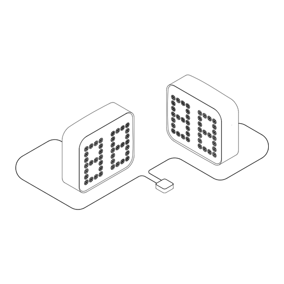
Page 14: Shotclock System Layout
CONSOLE KEYBOARD 6.2 Shotclock System Layout... - Page 15 SYSTEM LAYOUT 6.3 Wall Junction Box Wiring...
-
Page 16: Wall Junction Box Wiring
WALL JUNCTION BOX WIRING 6.4 Display Wiring and Layout... -
Page 17: Display Wiring
DISPLAY WIRING 6.5 Wiring Order Diagram... -
Page 18: Power Supply Diagram
WIRING ORDER 6.6 Power Supply Diagram... -
Page 19: Receiver Board Diagram
POWER SUPPLY 6.7 Receiver Board Diagram... - Page 20 DIP SWITCH SETTINGS: LED FUNCTIONS: 1 - On only when Rx is in SCBD D4 - Flashes very dimly with power up. 2 - On only when Rx is in shotclock (Indicates clock output on P1/channel 1.) 3 - Off (saved for future use) D5 - Flashes very dimly with power up.
-
Page 21: Microprocessor 4X7 Led Pattern (8 Bit)
6.8 Microprocessor 4X7 LED Pattern (8 Bit) LED PATTERN... - Page 22 6.9 Installation Diagram INSTALLATION DIAGRAM...
Need help?
Do you have a question about the MP-4299 and is the answer not in the manual?
Questions and answers