Table of Contents
Advertisement
Quick Links
Advertisement
Table of Contents

Related Manuals for Crestron CAGE3


Summary of Contents for Crestron CAGE3
- Page 1 Crestron CAGE3 Control Card Expansion Cage for AV3 Installation Guide...
-
Page 2: Table Of Contents
Electronics, Inc. in the United State and/or other countries. Other trademarks, registered trademarks and trade names may be used in this document to refer to either the entities claiming the marks and names or their products. Crestron disclaims any proprietary interest in the marks and names of others. -
Page 3: Control Card Expansion Cage For Av3: Cage3
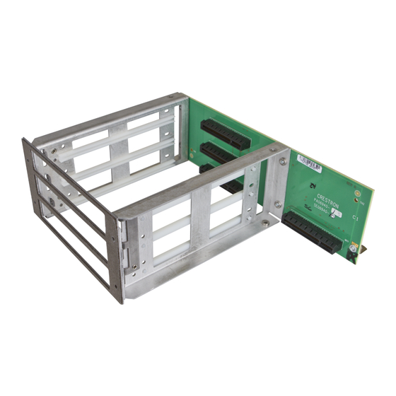
CAGE3 and the AV3 processor board. Two blank faceplates are attached to the CAGE3 when shipped. If more than one plug-in expansion card is to be utilized in the AV3, additional faceplate(s) must be removed. The expansion cards contain two thumbscrews that secure the card faceplate through the CAGE3 faceplate mounting brackets. - Page 4 Control Card Expansion Cage for AV3 Crestron CAGE3 CAGE3 Physical View CAGE3 Overall Dimensions (Rear View, As Installed) 3.18 in 2. 93 in (81 mm) (75 mm) 2 • Control Card Expansion Cage for AV3: CAGE3 Installation Guide – DOC. 7331A...
- Page 5 2 Mounting Nuts for Blank Faceplates to Attaching Cage to Chassis Cover Unused Card Slots (1 each side) 4 Mounting Holes for Card Panel Grounding Gasket Assembly to AV3 Installation Guide – DOC. 7331A Control Card Expansion Cage for AV3: CAGE3 • 3...
-
Page 6: Installation
Refer to the diagram below. Using a #2 Phillips screwdriver, remove eight cover top screws. CAGE3 Installation (1 of 13) - Remove Cover Top Screws 4 • Control Card Expansion Cage for AV3: CAGE3 Installation Guide – DOC. 7331A... - Page 7 Lift and remove AV3 cover. NOTE: During the next step, the four SEM (attached washer) screws must be retained to install the CAGE3. However, the blank plate is not reused. Refer to the diagram below. Use a #2 Phillips screwdriver to remove four rear-mounting SEM screws that secure the AV3 blank plate and remove the plate.
- Page 8 Then remove the long standoff mounting screw from under the chassis. Save the #6 flat head screw from the bottom of the chassis. CAGE3 Installation (4 of 13) - Remove Bottom-Mounting Screws & Nut Refer to the diagram below. Remove the #6 screw from the top of the long standoff and discard the standoff.
- Page 9 CAGE3 Installation (6 of 13) - Remove #4 Screw from Small Standoff Refer to the diagram below. Remove the top bracket from the vertical circuit board.
- Page 10 10. Refer to the diagram below. Reinstall the top bracket to the vertical circuit board using the two #4 screws saved from step 8. Attach the circuit board to the top bracket of the CAGE3 using the #6 screw saved from step 6. CAGE3 Installation (9 of 13) – Reinstall Circuit Board Bracket 8 •...
- Page 11 5 to finger-tight. Then, using a #2 Phillips tip screwdriver, tighten the screws an additional 1/8-turn. CAGE3 Installation (10 of 13) - Reinstall Bottom-Mounting Screws 12. Refer to the diagram below. Use a #2 Phillips tip screwdriver to reinstall and tighten the four rear-mounting screws that were removed in step 4.
- Page 12 16. Refer to the installation guide supplied with the expansion card for card installation instructions. If more than one plug-in expansion card is to be utilized in the AV3, additional faceplate(s) of the CAGE3 must be removed. 10 • Control Card Expansion Cage for AV3: CAGE3...
-
Page 13: Problem Solving
Crestron worldwide offices on the Crestron Web site (www.crestron.com/offices) for assistance within a particular geographic region. To post a question about Crestron products, log onto the Online Help section of the Crestron Web site (www.crestron.com/onlinehelp). First-time users must establish a user account to fully benefit from all available features. -
Page 14: Return And Warranty Policies
(property or economic damages inclusive) arising from the sale or use of this equipment. Crestron is not liable for any claim made by a third party or made by the purchaser for a third party. - Page 15 Crestron CAGE3 Control Card Expansion Cage for AV3 This page is intentionally left blank. This page is intentionally left blank. Installation Guide – DOC. 7331A Control Card Expansion Cage for AV3: CAGE3 • 13...
- Page 16 Crestron Electronics, Inc. Installation Guide – DOC. 7331A (2033001) 15 Volvo Drive Rockleigh, NJ 07647 Tel: 888.CRESTRON 11.12 Fax: 201.767.7576 Specifications subject to www.crestron.com change without notice.
Need help?
Do you have a question about the CAGE3 and is the answer not in the manual?
Questions and answers