Advertisement
Table of Contents
MPC3/MPB3-TTK-SQR
Tabletop Kit for MPC3-201
Installation Guide
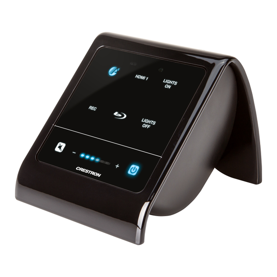
Description
The Crestron
MPC3/MPB3-TTK-SQR tabletop kit provides a tabletop enclosure for the
®
Crestron MPC3-201 3-Series
media presentation controller. The MPC3-201's front
®
panel is angled at a xed tilt of 45 degrees when installed in the enclosure. The complete
assembly may be placed on any at, level surface.
Additional Resources
Visit the product page on the Crestron website (www.crestron.com)
for additional information and the latest rmware updates. Use a QR
reader application on your mobile device to scan the QR image.
Installation
To install the MPC3/MPB3-TTK-SQR:
1. Prepare the MPC3-201 for installation into the MPC3/MPB3-TTK-SQR enclosure.
a. Insert the desired MPC3-201 icon chips into the appropriate label holders on the
rear of the MPC3-201 assembly. Icon chips are used as button labels for the
MPC3-201's backlit capacitive buttons.
b. Attach the MPC3-201 bezel to the assembly.
NOTE: For detailed instructions, refer to the MPC3-201 DO Guide (Doc. 7876) at
www.crestron.com/manuals.
2. Route the included Ethernet cable through the rear of the MPC3/MPB3-TTK-SQR
enclosure and out of the enclosure's front opening.
3. Connect the Ethernet cable to the LAN PoE port on the MPC3-201 assembly.
NOTE: The grounding cable included with the MPC3-201 may not be used when
the MPC3-201 is installed into the MPC3/MPB3-TTK-SQR enclosure.
4. Insert the MPC3-201 into the front opening of the MPC3/MPB3-TTK-SQR enclosure
as shown in the following illustration. The magnetic rear of the MPC3-201 assembly
snaps into place securely against the enclosure.
MPC3-201
Front opening
MPC3/MPB3-TTK-SQR
enclosure
5. Install the rubber cable grommet.
NOTE: Ensure that the side of the cable grommet labeled "INSIDE" is facing
toward the MPC3/MPB3-TTK-SQR enclosure during installation.
a. Push the Ethernet cable down into the opening in the cable grommet.
b. Push the cable grommet, top side rst, into its slot above the rear hole in the
MPC3/MPB3-TTK-SQR enclosure until it is secured in place.
MPC3/MPB3-TTK-SQR
Rubber cable
enclosure
grommet
6. Complete the MPC3-201 installation and con guration as described in the
MPC3-201 DO Guide (Doc. 7876).
NOTE: To remove the MPC3-201 from the MPC3/MPB3-TTK-SQR enclosure after
installation, use the bottom opening in the enclosure to push against the rear of the
MPC3-201 assembly until the magnetic hold between the MPC3-201 and the
enclosure is broken.
Ethernet
cable
Advertisement
Table of Contents

Related Manuals for Crestron MPB3-TTK-SQR


Summary of Contents for Crestron MPB3-TTK-SQR
- Page 1 2. Route the included Ethernet cable through the rear of the MPC3/MPB3-TTK-SQR enclosure and out of the enclosure’s front opening. 6. Complete the MPC3-201 installation and con guration as described in the MPC3-201 DO Guide (Doc. 7876).
- Page 2 Fax: 201.767.7576 Speci cations subject to names or their products. Crestron disclaims any proprietary interest in the marks and names of others. www.crestron.com change without notice.
Need help?
Do you have a question about the MPB3-TTK-SQR and is the answer not in the manual?
Questions and answers