
Related Manuals for ASROCK Rack 4U36L6E Series


Summary of Contents for ASROCK Rack 4U36L6E Series
- Page 1 4U36L6E Series User Manual Version 1.0 Published July 2022 Copyright©2022 ASRock Rack INC. All rights reserved.
- Page 2 In no event shall ASRock Rack, its directors, officers, employees, or agents be liable for any indirect, special, incidental, or consequential damages (including damages for loss of...
- Page 3 Setting up the Server in a Restricted Access Location • Access can only be gained by service persons or by users who have been instructed about the reasons for the restrictions applied to the location and about any precautions that shall be taken. •...
-
Page 4: Table Of Contents
Contents Chapter 1 Introduction Shipping Box Contents Specifications Chapter 2 Server System Overview System Components Internal Features System Front Panel System Rear Panel Front Control Panel Buttons and LEDs PSU LED Drive Tray LEDs & Lock Chapter 3 Hardware Installation and Maintenance Server Top Cover Hard Drive Power Supply... -
Page 5: Chapter 1 Introduction
4U36L6E Series Chapter 1 Introduction Thank you for purchasing 4U36L6E Series, a reliable barebone system produced under ASRock Rack’s consistently stringent quality control. It delivers excellent performance with robust design conforming to ASRock Rack’s commitment to quality and endurance. Because the hardware specifications might be updated, the content of this documentation will be subject to change without notice. -
Page 6: Shipping Box Contents
1.1 Shipping Box Contents Quantity Item 4U36L6E-MILAN2/2T 4U36L6E-ICX2/2T 4U36L6E Series Barebone System Boards (MB) Power Supply Units System Fans 3.5"/2.5" HDD Backplane (24-port BPB) 3.5" HDD Backplane (12-port BPB) 2.5" HDD Backplane (2-port BPB) Front Panel Boards Riser Card Power Distribution Boards (PDB) -
Page 7: Specifications
4U36L6E Series 1.2 Specifications 4U36L6E Series System Physical Status Form Factor 4U Rackmount Dimension 699 mm x 432 mm x 176 mm, 27.52” x 17.01” x 6.93” (D x W x H) Support MB Size • EEB, 12'' x 13" (ROME2D16-2T) •... -
Page 8: Chapter 2 Server System Overview
Chapter 2 Server System Overview This chapter provides diagrams showing the location of important components of the server system. 2.1 System Components Power Supply Units 2 x 2.5” Hot-Swap NVME Trays 7 x Hot-Swap System Fans (Upper 4 + Lower 3) 8 x PCIE Card Slots 12 x 3.5”... -
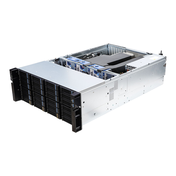
Page 9: Internal Features
4U36L6E Series 2.2 Internal Features From Add-on Card Slots Rear I/O Panel (depends on the specification of the server board) 12 x 3.5" SAS/SATA Drive Trays 2 x 2.5" NVME Drive Trays 2 x Power Supply Units Serverboard 7 x System Fans (upper 3 + lower 4) 20 x 3.5"... -
Page 10: System Front Panel
2.3 System Front Panel Description Control Panel Buttons and LEDs 20 x 3.5" SATA/SAS HDD Trays 4 x 3.5" SATA/SAS HDD or 2.5" NVMe HDD Trays 2 x USB 3.2 Gen1 Ports Rack mount screws hole The HDD trays marked with blue color at the front side of the chassis are for 3.5" SATA/ SAS drives only. -
Page 11: System Rear Panel
4U36L6E Series 2.4 System Rear Panel Redundant PSU 1+1: Only one PSU is allowed to be removed while the server is running. WARNING! Do NOT open the tray if the server is not powered down or while it is still running. -
Page 12: Front Control Panel Buttons And Leds
2.5 Front Control Panel Buttons and LEDs Description Reset Button Power Button Power LED System Alarm LED* LAN1 Activity LED* LAN2 Activity LED* *Please be noted that the functions are supported depending on the type of the server board. Power Button Press the power switch button to toggle the system power on and standby/sleep modes. - Page 13 4U36L6E Series Status LED Definitions Power LED Status Description Green Power on Power off ID LED Status Description Blue System identification is active. System identification is disabled. LAN Activity LED Status Description Green Link between system and network or no access...
-
Page 14: Psu Led
2.6 PSU LED PSU LED PSU Status LED Status Description Green Normal work; output ON and OK Amber Module fault/protection in operating mode (failure, OCP, OVP, Fan Fail, OTP, UVP) AC cord unplugged Amber blinking at 0.5Hz Warning (high temp, high power, high current, slow fan) Green blinking at 0.5Hz AC Present Only 12VSB on (PS off) or PS in Smart Redundant state... -
Page 15: Drive Tray Leds & Lock
4U36L6E Series 2.7 Drive Tray LEDs & Lock Description HDD Power LED HDD Activity LED Status LED Definitions HDD Power LED Status Description Blue HDD powered-on No power to HDD HDD Activity LED Status Description Solid Green HDD active Blinking Green... -
Page 16: Chapter 3 Hardware Installation And Maintenance
Chapter 3 Hardware Installation and Maintenance This chapter helps you assemble the chassis and install components. Before You Begin Before you work with the server, pay close attention to the “Important Safety Instructions” at the beginning of this manual. 1. Make sure the server is powered off. Power down the server if it is still running. -
Page 17: Server Top Cover
4U36L6E Series 3.1 Server Top Cover Removing the Server Top Cover 1. Before removing the top covers, power off the server and unplug the power cord. 2. The system must be operated with all the chassis top covers installed to ensure proper cooling. - Page 18 Installing the Server Top Cover 1. Lower the top cover on the chassis, making sure the side latches align with the cutouts. 2. Slide the top cover toward the FRONT of the chassis. 3. Secure the top cover with the screw.
-
Page 19: Hard Drive
4U36L6E Series 3.2 Hard Drive 3.2.1 Installing a Hard Disk Drive into 2.5" Hard Drive Tray The system supports hot-swappable 2.5" hard drives. The 2.5" hard drive trays are located on the rear side of the chassis. Removing 2.5” Hard Drive Trays from the Chassis 1. - Page 20 Installing a 2.5” Hard Drive to the Hard Drive Tray 1. Place a 2.5" HDD into the tray with the printed circuit board side facing down. Carefully align the mounting holes in the hard drive and the tray. 2. Secure the hard drive using the screws. 3.
- Page 21 4U36L6E Series 3.2.2 Installing a Hard Disk Drive into 3.5" Hard Drive Tray The system supports hot-swappable 3.5" hard drives. The 3.5" hard drive trays are located on both the front and rear sides of the chassis. Removing 3.5” Hard Drive Trays from the Chassis 1.
- Page 22 Installing a 3.5” Hard Drive to the Hard Drive Tray 1. Place a 3.5" HDD into the tray with the printed circuit board side facing down. 2. Directly place a HDD into the tool-less HDD tray untli it snaps. 3. Slide the drive tray into the HDD bay until the drive is fully seated. 4.
- Page 23 4U36L6E Series Installing a 2.5” Hard Drive to the 3.5” Hard Drive Tray The HDD trays marked with orange color at the front side of the chassis can support both 3.5" SATA/SAS drives and 2.5" NVMe drives. 1. Place a 2.5" HDD into the 3.5" HDD tray with the printed circuit board side facing down.
-
Page 24: Power Supply
3.3 Power Supply Installing and Removing the Power Supply Before replacing the power supply, power off the server, unplug the power cord, and discon- nect all wiring from the power supply. Installing the Power Supply Unit The 4U36L2S / 4U36L2E Series can accommodate two AC or two DC power supplies in the bay at the rear of the chassis. - Page 25 4U36L6E Series Removing the Power Supply Unit To remove a failed power supply, identify the failed power supply by checking the power supply LED on the PSU. 1. Hold onto the power supply handle while pressing the locking lever towards the power supply handle.
-
Page 26: System Fan
3.4 System Fan This system supports hot-swappable system fans. Replacing the System Fan 1. Squeeze the fan handles together, and then lift the failed fan out of the server. 2. Before installing a new fan, make sure the fan connector on the fan module is on the left, when you are facing the rear side of the chassis. -
Page 27: Pci Express Card (Low-Profile)
4U36L6E Series 3.5 PCI Express Card (Low-Profile) Installing and Removing the PCIE Card 1. Release the screw that secures the slot cover to the chassis. 2. Remove the slot cover. - Page 28 3. Install a PCIE card into the slot. 4. Make sure that the card is well seated and tighten the screw on the face plate.
-
Page 29: Serverboard Tray
4U36L6E Series 3.6 Serverboard Tray Installing and Removing the Serverboard Tray Please remove the fan bar before removing the serverboard tray. 1. Remove eight screws that secure the serverboard tray to the chassis. 2. Pull to remove the power supply from the chassis. -
Page 30: Air Duct
3.7 Air Duct Install the Air Duct on the Rear HDDs 1. Align the tab on the front edge of the air duct with the fan bar on the fan assembly. 2. Lower the air duct into the chassis ensuring the tab is securely installed between the fan bar and the fan module. - Page 31 4U36L6E Series Install the Air Duct on the Heatsink 1. Align the tab on the front edge of the air duct with the fan bar on the fan assembly. 2. Lower the air duct into the chassis ensuring the tab is securely installed between the...
- Page 32 Make sure both air ducts are well installed.
-
Page 33: Installing The Cpu (4U36L6E-Milan2/2T)
4U36L6E Series Appendix A Please refer to the user's manual of the serverboard for more information of the serverboard components. Installing the CPU (4U36L6E-MILAN2/2T) 1. Before you insert the CPU into the socket, please check if the PnP cap is on the socket, if the CPU surface is unclean, or if there are any bent pins in the socket. - Page 35 4U36L6E Series Carr ier Frame with CPU Rail Frame Please make sure that the carrier frame with CPU is closely attached to the rail frame while inserting it. Install the carrier frame with CPU. Don’t separate them.
-
Page 37: Installing The Cpu (4U36L6E-Icx2/2T)
4U36L6E Series Installing the CPU (4U36L6E-ICX2/2T) 1. Before you insert the CPU into the socket, please check if the PnP cap is on the socket, if the CPU surface is unclean, or if there are any bent pins in the socket. Do not force to insert the CPU into the socket if above situation is found. - Page 38 1. Before you installed the heatsink, you need to spray thermal interface material between the CPU and the heatsink to improve heat dissipation. 2. Illustration in this documentation are examples only. Heatsink or fan cooler type may differ. CPU Carrier...
- Page 39 4U36L6E Series...
- Page 40 CPU Carrier...
- Page 41 4U36L6E Series Heatsink CPU Carrier Socket...
-
Page 43: Installation Of Memory Modules (Dimm)
4U36L6E Series Installation of Memory Modules (DIMM)
Need help?
Do you have a question about the 4U36L6E Series and is the answer not in the manual?
Questions and answers