
Related Manuals for ASROCK Rack 4U10G-GENOA2


Summary of Contents for ASROCK Rack 4U10G-GENOA2
- Page 2 In no event shall ASRock Rack, its directors, officers, employees, or agents be liable for any indirect, special, incidental, or consequential damages (including damages for loss of profits, loss of business, loss of data, interruption of business and the like), even if ASRock Rack has been advised of the possibility of such damages arising from any defect or error in the documentation or product.
- Page 3 “Perchlorate Material-special handling may apply, see www.dtsc.ca.gov/hazardouswaste/ perchlorate” ASRock Rack’s Website: www.ASRockRack.com Setting up the Server in a Restricted Access Location/Restricted Access Area • Access can only be gained by service persons or by users who have been instructed about the reasons for the restrictions applied to the location and about any precautions that shall be taken.
- Page 4 Replaceable Batteries CAUTION RISK OF EXPLOSION IF BATTERY IS REPLACED BY AN INCORRECT TYPE. DISPOSE OF USED BATTERIES ACCORDING TO THE INSTRUCTIONS Warning When removal of the chassis lid required for servicing: - Turn off power and unplug any power cords/cables, and - Reinstall the chassis lid before restoring power.
- Page 5 Contents Chapter 1 Introduction Shipping Box Contents Specifications Chapter 2 Server System Overview System Components Internal Features System Front Panel System Rear Panel Control Panel Buttons and LEDs PSU LED Drive Tray LEDs & Lock Chapter 3 Hardware Installation and Maintenance Server Top Cover Hard Drive Power Supply...
- Page 7 4U10G-GENOA2 Chapter 1 Introduction Thank you for purchasing 4U10G-GENOA2, a reliable barebone system produced under ASRock Rack’s consistently stringent quality control. It delivers excellent performance with robust design conforming to ASRock Rack’s commitment to quality and endurance. This guide provides the instructions of insertion and extraction of chassis components, such as chassis covers, system fans, power supplies, hard disk drive trays, and other main components this system supports.
- Page 8 1.1 Shipping Box Contents Item Quantity 4U Series Barebone System Boards (MB) Power Supply Unit (PSU) Rear System Fans Middle System Fans Hard Drive Backplane (BPB) Rear Panel Board Power Distribution Board (PDB) Rear Fan Board Middle Fan Board Switch Board (SWB) Accessory Box Quick Installation Guide Rail Assembly Kit...
- Page 9 4U10G-GENOA2 1.2 Specifications 4U10G-GENOA2 System Physical Status Form Factor 4U Rackmount Dimensions 786 x 438 x 176.5 mm (30.9'' x 17.2'' x 6.9'') Support MB GENOA2D24G-2L+ Front Panel • Power button w/ LED • Reset button Buttons • NMI button •...
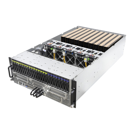
- Page 10 Chapter 2 Server System Overview This chapter provides diagrams showing the location of important components of the server system. 2.1 System Components 10 GPU Card Slots Server Board 16 Hot-swap 2.5" NVMe (PCIe5.0 x4) drive bays 24 Hot-swap 2.5" SATA/SAS* 5 x Middle Hot-Swap drive bays 80x80 mm Fans...
- Page 11 4U10G-GENOA2 2.2 Internal Features...
- Page 12 From Common Redundant Power Supply 1 Common Redundant Power Supply 2 Common Redundant Power Supply 3 Common Redundant Power Supply 4 Switch Board (SWB) Power Distribution Board (PDB) System Fan 1 System Fan 2 System Fan 3 System Fan 4 System Fan 5 Serverboard Hard Drive Backplane Board (BPB)
- Page 13 4U10G-GENOA2 2.3 System Front Panel Description 16 x Hot-swap 2.5" NVMe (PCIe5.0 x4) drive bays 24 x Hot-swap 2.5" SATA/SAS* drive bays *Additional RAID/HBA card required to support the 24 x 2.5” SATA/SAS drive bays. 1 x Add-in Card Slots (PCIe FHHL) I/O Shield (depends on the specification of the server board) 1 x OCP NIC 3.0 (PCIe5.0 x8)
- Page 14 2.5 Control Panel Buttons and LEDs Front Control Panel Rear Control Panel Description UID Button and LED Power Button and LED System Reset Button NMI (Nonmaskable Interrupt) Button System Event LED Hard Drive Activity LED *Please be noted that certain functions are supported depending on the type of the server board.
- Page 15 4U10G-GENOA2 Power Button Press the power switch button to toggle the system power on and standby/sleep modes. To remove all power from the system completely, disconnect the power cord from the server. UID Button Press the ID button to toggle the front panel UID LED and the baseboard UID LED on and off.
- Page 16 2.6 PSU LED PSU LED PSU Status LED Status Description Green Normal work; output ON and OK Amber Module fault/protection in operating mode (failure, OCP, OVP, Fan Fail, OTP, UVP) AC cord unplugged Amber blinking at 0.5Hz Warning (high temp, high power, high current, slow fan) Green blinking at 0.5Hz AC Present Only 12VSB on (PS off) or PS in Smart Redundant state...
- Page 17 4U10G-GENOA2 2.7 Drive Tray LEDs Description Hard Drive Trays Power LED Hard Drive Trays Activity LED Status LED Definitions Hard Drive Trays Power LED Status Description Blue Hard Drive Trays powered-on No power to Hard Drive Trays Hard Drive Trays Activity LED...
- Page 18 Chapter 3 Hardware Installation and Maintenance This chapter helps you assemble the chassis and install components. Before You Begin Before you work with the server, pay close attention to the “Important Safety Instructions” at the beginning of this manual. 1. Make sure the server is powered off. Power down the server if it is still running.
- Page 19 4U10G-GENOA2 3.1 Server Top Cover Removing the Server Top Covers 1. Before removing the top covers, power off the server and unplug the power cord. 2. The system must be operated with all the chassis top covers installed to ensure proper cooling.
- Page 20 Removing the Server Top Front Cover 1. Remove the screw that secures the top rear cover to the chassis 2. Push straight back to remove the cover from the locked position. Then lift up and remove the cover.
- Page 21 4U10G-GENOA2 Installing the Server Top Rear Cover 1. Lower the top front cover on the chassis, making sure the side latches align with the cutouts. 2. Hand-tighten the thumbscrew on the rear side of the chassis. 3. Slide the top cover toward the FRONT of the chassis. Then secure the top cover with...
- Page 22 Installing the Server Top Front Cover 1. Lower the top front cover on the chassis, making sure the side latches align with the cutouts. Slide the top front cover toward the FRONT of the chassis. 2. Slide the top cover toward the FRONT of the chassis. Then secure the top cover with the screws.
- Page 23 4U10G-GENOA2 3.2 Hard Drive 3.2.1 Installing a Hard Disk Drive into 2.5" or 3.5" Hard Drive Tray The system supports hot-swappable 3.5" or 2.5" hard drives. The hard drive trays are located on the front of the chassis. Removing Hard Drive Trays from the Chassis 1.
- Page 24 Installing a Hard Drive to the Hard Drive Tray 1. Engage two embossed pins into the side dimples on the tray. 2. Carefully push down the other side of the tray until the other two embossed pins and side dimples lock into place. 3.
- Page 25 4U10G-GENOA2 3.3 Power Supply The system can accommodate four AC or two DC power supplies in the bay at the rear of the chassis. Each unit provides up to 1600 Watts (200V AC) of power. Three power supplies are required for full load operation, with the fourth power supply purely as a redundant, load-sharing backup.
- Page 26 Removing the Power Supply Unit To remove a failed power supply, identify the failed power supply by checking the power supply LEDs on the PSU. 1. Hold onto the power supply handle while pressing the locking lever towards the power supply handle.
- Page 27 4U10G-GENOA2 3.4 System Fan The system supports hot-swappable system fans. Replacing the System Fan (Middle) 1. Lift to remove the failed fan. 2. Align the mounting holes on the replacement fan corners with the fan mounts on the fan bracket.
- Page 28 3.5 Add-in Card Removing the PCIe Riser Card Assembly from the Chassis 1. Loosen the screws that secure the add-in card bracket to the chassis. 2. Lift up the Hard Disk Drive bracket. 3. Loosen the screws on the riser card assembly. 4.
- Page 29 4U10G-GENOA2 Installing the PCIe Add-in Card 1. Install a PCIe add-on card in the riser card assembly. Make sure that the PCIe card is correctly seated. 2. Tighten the screw to secure the PCIe card to the riser card assembly.
- Page 30 Appendix A Installing the CPU (LGA 6096 Socket) 1. Before inserting the CPU into the socket, please check if the PnP cap is on the socket, if the CPU surface is unclean, or if there are any bent pins in the socket. Do not force to insert the CPU into the socket if above situation is found.
- Page 31 4U10G-GENOA2...
- Page 32 Carr ier Frame with CPU Rail Frame Please make sure that the carrier frame with CPU is closely attached to the rail frame while inserting it. Install the carrier frame with CPU. Don’t separate them.
- Page 33 4U10G-GENOA2...
- Page 34 Set your torque wrench to 1.54 in-lb. One fourth a turn each time. Tighten the screws in a sequential order 1 > 2 > 3 > 4 > 5 > 6. Loosen the screws in a reverse order. 10-4 10-2 10-5 10-6 10-1...
- Page 35 4U10G-GENOA2 Installation of Memory Modules (DIMM) The DIMM only fits in one correct orientation. It will cause permanent damage to the motherboard and the DIMM if you force the DIMM into the slot at incorrect orientation. For more information about DIMM installation, please refer to the User Manual that comes with the server board used.
- Page 36 Type B (Two Clips)
- Page 37 4U10G-GENOA2 Appendix B Block Diagram (GENOA2D24G-2L+)
- Page 38 Contact Information Contact ASRock Rack or want to know more about ASRock Rack, you’re welcome to visit ASRock Rack’s website at http://www.asrockrack.com; or contact the dealer for further information. For technical questions, please submit a support request form at https://event.
Need help?
Do you have a question about the 4U10G-GENOA2 and is the answer not in the manual?
Questions and answers