
Related Manuals for Supermicro SUPERSERVER 6018U-TR4+


Summary of Contents for Supermicro SUPERSERVER 6018U-TR4+
- Page 1 UPER ERVER ® 6018U-TR4+ 6018U-TRT+ 6018U-TR4T+ 6018U-TRTP+ USER’S MANUAL Revision 1.0e...
- Page 2 This product, including software and documentation, is the property of Supermicro and/or its licensors, and is supplied only under a license. Any use or reproduction of this product is not allowed, except as expressly permitted by the terms of said license.
- Page 3 This manual may be periodically updated without notice. Please check the Supermicro Web site for possible updates to the manual revision level. Secure Data Deletion A secure data deletion tool designed to fully erase all data from storage devices can be found on our website: https://www.supermicro.com/about/policies/disclaimer.
-
Page 4: Table Of Contents
System Power ....................1-3 Drives ......................1-3 PCI Expansion Slots ..................1-3 Front Control Panel ..................1-3 Cooling System ....................1-3 Contacting Supermicro ..................1-5 Chapter 2 Server Installation Overview ......................2-1 Unpacking the System ..................2-1 Preparing for Setup ..................2-1 Choosing a Setup Location ................ - Page 5 Preface Drive Carrier LEDs ..................3-4 Power Supply LEDs ..................3-4 Chapter 4 Standardized Warning Statements for AC Systems About Standardized Warning Statements ............4-1 Warning Definition ................... 4-1 Installation Instructions ..................4-4 Circuit Breaker ....................4-5 Power Disconnection Warning ................ 4-6 Equipment Installation ..................
- Page 6 UPER ERVER 6018U-T Series Manual 5-10 Onboard Indicators ..................5-20 5-11 SATA Ports ....................5-21 5.12 Microsoft Windows OS Installation ............... 5-22 5-13 Installing Software ..................5-24 SuperDoctor 5 ..................... 5-25 ® 5.14 IPMI ....................... 5-26 BMC ADMIN User Password ................ 5-26 5-15 Onboard Battery ....................
-
Page 7: Chapter 1 Introduction
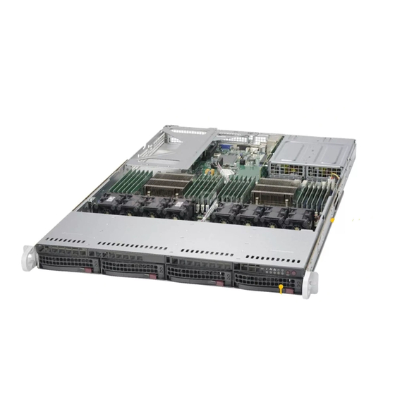
The SuperServer 6018U-T Series is a high-end server comprised of the SC819UTQ-R750 1U server chassis and the X10DRU-i+ dual processor serverboard. Refer to the Supermicro web site (www.supermicro.com) for information on operating systems that have been certified for use with the system. -
Page 8: Serverboard Features
Figure 1-1 shows a block diagram of the chipset. Processors The server supports single or dual E5-2600 v3/v4 series processors in R3 LGA 2011 sockets (Socket R3). Refer to the Supermicro web site for a complete listing of supported processors. Memory... -
Page 9: Server Chassis Features
Chapter 1: Introduction Server Chassis Features The 6018U-T Series is built upon the SC819UTQ-R750 chassis. Details on the chassis and on servicing procedures can be found in Chapter 6. The following is a general outline of the main features of the chassis. System Power The chassis features a redundant 750W power supply consisting of two power modules, so one may be replaced without powering down the system. - Page 10 UPER ERVER 6018U-T Series User's Manual DDR3 NCSI UART Port A Port B Port B Onboard TPM (Optional) 8~15 Port C 0~10 Port 3 Port 0, 1 Port C Type A 11~15 Rear PE1 PE2 PE3 QPI1 QPI0 QPI1 QPI0 PE1 PE2 PE3 Processor Processor...
-
Page 11: Contacting Supermicro
Super Micro Computer, Inc. 980 Rock Ave. San Jose, CA 95131 U.S.A. Tel: +1 (408) 503-8000 Fax: +1 (408) 503-8008 Email: marketing@supermicro.com (General Information) support@supermicro.com (Technical Support) Web Site: www.supermicro.com Europe Address: Super Micro Computer B.V. Het Sterrenbeeld 28, 5215 ML... - Page 12 UPER ERVER 6018U-T Series User's Manual Notes...
-
Page 13: Chapter 2 Server Installation
Chapter 2: Server Installation Chapter 2 Server Installation Overview This chapter provides a quick setup checklist to get your system up and running. This quick setup assumes that your system has come to you with the processors and memory preinstalled. If your system is not already fully integrated with a serverboard, processors, system memory etc., please turn to the chapter or section noted in each step for details on installing specific components. -
Page 14: Warnings And Precautions
SUPERSERVER 6018U-T Series User's Manual Warnings and Precautions Rack Precautions • Ensure that the leveling jacks on the bottom of the rack are fully extended to the floor with the full weight of the rack resting on them. • In single rack installation, stabilizers should be attached to the rack. In multiple rack installations, the racks should be coupled together. -
Page 15: Rack Mounting Considerations
Chapter 2: Server Installation Rack Mounting Considerations Ambient Operating Temperature If installed in a closed or multi-unit rack assembly, the ambient operating temperature of the rack environment may be greater than the ambient temperature of the room. Therefore, consideration should be given to installing the equipment in an environment compatible with the manufacturer’s maximum rated ambient temperature (Tmra). -
Page 16: Installing The System Into A Rack
SUPERSERVER 6018U-T Series User's Manual Installing the System into a Rack This section provides information on installing the chassis into a rack unit with the rails provided. There are a variety of rack units on the market, which may mean that the assembly procedure differs slightly. -
Page 17: Installing The Optional Inner Rail Extensions
Chapter 2: Server Installation Installing the Optional Inner Rail Extensions Attaching the optional inner rail extensions allows you to pull the server farther out of the rack. Do not put downward force on the chassis when it is fully extended. Installing the Inner Rail Extensions 1. -
Page 18: Assembling The Outer Rails
SUPERSERVER 6018U-T Series User's Manual Assembling the Outer Rails Each outer rail comes in two sections that must be assembled before mounting onto the rack. Assembling the Outer Rails 1. Identify the left and right outer rails by examining the ends, which bend outward. Match the left front outer rail with the left rear outer rail and the same for the right rails. -
Page 19: Installing The Outer Rails Onto The Rack
Chapter 2: Server Installation Installing the Outer Rails onto the Rack Each end of the assembled outer rail includes a bracket with square pegs to fit into your rack holes. If you have an older rack with round holes, these brackets must be removed, and you must use screws to secure the rail to the rack. -
Page 20: Installing And Removing The Chassis From A Rack
SUPERSERVER 6018U-T Series User's Manual Installing and Removing the Chassis From a Rack Installation into a Rack 1. Slide the inner rail extensions into the front of the outer rails. 2. Push the chassis backward into the rack until it clicks into the locked postion. Removing the Chassis From a Rack Press the outer rail latch to release the chassis. -
Page 21: Installing The Server Into A Telco Rack
Chapter 2: Server Installation Installing the Server into a Telco Rack Optional brackets are needed to install the server to a telco (open type) rack. To install the server into a Telco type rack, use the two L-shaped brackets on either side of the chassis (four total). - Page 22 SUPERSERVER 6018U-T Series User's Manual Notes 2-10...
-
Page 23: Chapter 3 System Interface
Chapter 3: System Interface Chapter 3 System Interface Overview The chassis includes: • A control panel on the front that houses power buttons and status monitoring lights • Status lights on externally accessible hard drives • Status lights for the power supply visible from the back of the chassis These elements are described in this chapter with possible responses. -
Page 24: Control Panel Buttons
SUPERSERVER 6018U-T Series User's Manual Control Panel Buttons The chassis includes three push-buttons. Power: The main power switch applies or removes power from the power supply to the server system. Turning off system power with this button removes the main power but standby power is still supplied to the system. -
Page 25: Overheating
Some backplanes allow the overheat temperature to be set at 45, 50, or 55 by changing a jumper setting. For more information, consult the backplane user manual at www.supermicro.com. (Click Support, then the Manuals link.) Responses If the server overheats: 1. -
Page 26: Drive Carrier Leds
Blinking Amber: When blinking, indicates that the power supply has a warning condition and continues to operate. • Solid Amber: When illuminated, indicates that the power supply is plugged in and in an abnormal state. The server system might need service. Please contact Supermicro technical support. -
Page 27: Chapter 4 Standardized Warning Statements For Ac Systems
Only certified technicians should attempt to install or configure components. Read this chapter in its entirety before installing or configuring components in the Supermicro chassis. Some warnings may not apply for your system. These warnings may also be found on our web site at www.supermicro.com/about/ policies/safety_information.cfm. - Page 28 SUPERSERVER 6018U-T Series User's Manual Warnung WICHTIGE SICHERHEITSHINWEISE Dieses Warnsymbol bedeutet Gefahr. Sie befinden sich in einer Situation, die zu Verletzungen führen kann. Machen Sie sich vor der Arbeit mit Geräten mit den Gefahren elektrischer Schaltungen und den üblichen Verfahren zur Vorbeugung vor Unfällen vertraut.
- Page 29 Chapter 4: Warning Statements for AC Systems !تحذٌز جسذٌة اصابة ًتتسبب ف حالة ٌوكي أى ًاًك ف خطز ًٌٌع هذا الزهز الذوائز بالوخاطز الٌاجوة عي ي على علن ، ك هعذات تعول على أي قبل أى الكهزبائٍة حىادث أي وقىع وٌع...
-
Page 30: Installation Instructions
SUPERSERVER 6018U-T Series User's Manual Installation Instructions Warning! Read the installation instructions before connecting the system to the power source. 設置手順書 システムを電源に接続する前に、 設置手順書をお読み下さい。 警告 将此系统连接电源前,请先阅读安装说明。 警告 將系統與電源連接前,請先閱讀安裝說明。 Warnung Vor dem Anschließen des Systems an die Stromquelle die Installationsanweisungen lesen. ¡Advertencia! Lea las instrucciones de instalación antes de conectar el sistema a la red de alimentación. -
Page 31: Circuit Breaker
Chapter 4: Warning Statements for AC Systems Circuit Breaker Warning! This product relies on the building's installation for short-circuit (overcurrent) protection. Ensure that the protective device is rated not greater than: 250 V, 20 A. サーキッ ト ・ ブレーカー この製品は、 短絡 (過電流) 保護装置がある建物での設置を前提としています。 保護装置の定格が250 V、... -
Page 32: Power Disconnection Warning
SUPERSERVER 6018U-T Series User's Manual 경고! 이 제품은 전원의 단락(과전류)방지에 대해서 전적으로 건물의 관련 설비에 의존합니다. 보호장치의 정격이 반드시 250V(볼트), 20A(암페어)를 초과하지 않도록 해야 합니다. Waarschuwing Dit product is afhankelijk van de kortsluitbeveiliging (overspanning) van uw electrische installatie. Controleer of het beveiligde aparaat niet groter gedimensioneerd is dan 220V, 20A. - Page 33 Chapter 4: Warning Statements for AC Systems ¡Advertencia! El sistema debe ser disconnected de todas las fuentes de energía y del cable eléctrico quitado de los módulos de fuente de alimentación antes de tener acceso el interior del chasis para instalar o para quitar componentes de sistema. Attention Le système doit être débranché...
-
Page 34: Equipment Installation
SUPERSERVER 6018U-T Series User's Manual Equipment Installation Warning! Only trained and qualified personnel should be allowed to install, replace, or service this equipment. 機器の設置 トレーニングを受け認定された人だけがこの装置の設置、 交換、 またはサービスを許可 されています。 警告 只有经过培训且具有资格的人员才能进行此设备的安装、更换和维修。 警告 只有經過受訓且具資格人員才可安裝、更換與維修此設備。 Warnung Das Installieren, Ersetzen oder Bedienen dieser Ausrüstung sollte nur geschultem, qualifiziertem Personal gestattet werden. -
Page 35: Restricted Area
Chapter 4: Warning Statements for AC Systems Waarschuwing Deze apparatuur mag alleen worden geïnstalleerd, vervangen of hersteld door geschoold en gekwalificeerd personeel. Restricted Area Warning! This unit is intended for installation in restricted access areas. A restricted access area can be accessed only through the use of a special tool, lock and key, or other means of security. -
Page 36: Battery Handling
SUPERSERVER 6018U-T Series User's Manual א א ז ז ו ו ר ר ע ע ם ם ג ג י י ש ש ה ה מ מ ו ו ג ג ב ב ל ל ת ת ! ! א א ז ז ה ה ר ר ה ה יש... - Page 37 Chapter 4: Warning Statements for AC Systems Warnung Bei Einsetzen einer falschen Batterie besteht Explosionsgefahr. Ersetzen Sie die Batterie nur durch den gleichen oder vom Hersteller empfohlenen Batterietyp. Entsorgen Sie die benutzten Batterien nach den Anweisungen des Herstellers. Attention Danger d'explosion si la pile n'est pas remplacée correctement. Ne la remplacer que par une pile de type semblable ou équivalent, recommandée par le fabricant.
-
Page 38: Redundant Power Supplies (If Applicable To Your System)
SUPERSERVER 6018U-T Series User's Manual Redundant Power Supplies (if applicable to your system) Warning! This unit might have more than one power supply connection. All connections must be removed to de-energize the unit. 冗長電源装置 このユニッ トは複数の電源装置が接続されている場合があります。 ユニッ トの電源を切るためには、 すべての接続を取り外さなければなりません。 警告 此部件连接的电源可能不止一个,必须将所有电源断开才能停止给该部件供电。... -
Page 39: Backplane Voltage (If Applicable To Your System)
Chapter 4: Warning Statements for AC Systems امداد الطاقة بوحدات عدة اتصاالت جهاز ال يكون لهذا قد الكهرباء عن وحدة ال لعسل كافة االتصاالت يجب إزالة 경고! 이 장치에는 한 개 이상의 전원 공급 단자가 연결되어 있을 수 있습니다. 이 장치에... -
Page 40: Comply With Local And National Electrical Codes
SUPERSERVER 6018U-T Series User's Manual מ מ ת ת ח ח ב ב פ פ נ נ ל ל ה ה א א ח ח ו ו ר ר י י !הרה אז קיימת סכנת מתח בפנל האחורי בזמן תפעול המערכת. יש להיזהר במהלך .העבודה... -
Page 41: Product Disposal
Chapter 4: Warning Statements for AC Systems Attention L'équipement doit être installé conformément aux normes électriques nationales et locales. ת ת י י א א ו ו ם ם ח ח ו ו ק ק י י ה ה ח ח ש ש מ מ ל ל ה ה א א ר ר צ צ י י !אזהרה... -
Page 42: Hot Swap Fan Warning
SUPERSERVER 6018U-T Series User's Manual ¡Advertencia! Al deshacerse por completo de este producto debe seguir todas las leyes y reglamentos nacionales. Attention La mise au rebut ou le recyclage de ce produit sont généralement soumis à des lois et/ou directives de respect de l'environnement. Renseignez-vous auprès de l'organisme compétent. - Page 43 Chapter 4: Warning Statements for AC Systems 警告 當您從機架移除風扇裝置,風扇可能仍在轉動。小心不要將手指、螺絲起子和其他 物品太靠近風扇。 Warnung Die Lüfter drehen sich u. U. noch, wenn die Lüfterbaugruppe aus dem Chassis genommen wird. Halten Sie Finger, Schraubendreher und andere Gegenstände von den Öffnungen des Lüftergehäuses entfernt. ¡Advertencia! Los ventiladores podran dar vuelta cuando usted quite ell montaje del ventilador del chasis.
-
Page 44: Power Cable And Ac Adapter
Electrical Appliance and Material Safety Law prohibits the use of UL or CSA -certified cables (that have UL/CSA shown on the code) for any other electrical devices than products designated by Supermicro only. 電源コードとACアダプター 製品を設置する場合、 提供または指定された接続ケーブル、 電源コードとACアダプター... - Page 45 Appareils électroménagers et de loi sur la sécurité Matériel interdit l'utilisation de UL ou CSA câbles certifiés qui ont UL ou CSA indiqué sur le code pour tous les autres appareils électriques que les produits désignés par Supermicro seulement.
- Page 46 SUPERSERVER 6018U-T Series User's Manual Notes 4-20...
-
Page 47: Chapter 5 Advanced Serverboard Setup
Chapter 5: Advanced Serverboard Setup Chapter 5 Advanced Serverboard Setup This chapter covers the steps required to install processors and heatsinks to the X10DRU-i+ serverboard, connect the data and power cables and install add-on cards. All serverboard jumpers and connections are described and a layout and quick reference chart are included in this chapter. -
Page 48: Installing The Processor And Heatsink
• Install the processor into the CPU socket before installing the heatsink. • Refer to the Supermicro web site for updates on CPU support. Installing an LGA 2011 Processor Installing a CPU 1. There are two levers on the LGA 2011 socket. - Page 49 Chapter 5: Advanced Serverboard Setup 3. W ith the sec ond lever f ully Open the load plate. retracted, gently push down on the "Open 1st" lever to loosen the load plate. Lift the load plate with your fingers to open it completely. 4.
- Page 50 UPER ERVER 6018U-T Series User's Manual Gently close the load plate. 7. With the "Close 1st" lever fully retracted, gently close the load plate. Push down and lock the lever labeled "Close 1st". 8. Make sure the locking mechanism on the "Close 1st" lever catches the lip of the load plate.
-
Page 51: Installing A Cpu Heatsink
Chapter 5: Advanced Serverboard Setup Installing a CPU Heatsink 1. Place the heatsink on top of the CPU so that the four mounting holes are aligned with those on the retention mechanism. 2. Screw in two diagonal screws (i.e. the #1 and the #2 screws) until just snug (do not over-tighten the screws, which may damage the CPU.) 3. -
Page 52: Connecting Cables
UPER ERVER 6018U-T Series User's Manual Connecting Cables Now that the processors are installed, the next step is to connect the cables to the serverboard. These include the data (ribbon) cables for the peripherals and control panel and the power cables. Connecting Data Cables The cables used to transfer data from the peripheral devices have been carefully routed in preconfigured systems to prevent them from blocking the flow of cooling... -
Page 53: I/O Ports
Chapter 5: Advanced Serverboard Setup I/O Ports The I/O ports at the rear of the server are pictured below.. Figure 5-2. Rear Panel I/O Ports 1. Back Panel USB 3.0 Port 0 2. Back Panel USB 3.0 Port 1 3. BMC dedicated LAN 4. -
Page 54: Installing Memory
UPER ERVER 6018U-T Series User's Manual Installing Memory Note: Check the Supermicro web site for recommended memory modules. CAUTION Exercise extreme care when installing or removing DIMM modules to prevent any possible damage. Installing DIMMs 1. Insert the desired number of DIMMs into the memory slots, starting with slot DIMMA1. -
Page 55: Memory Support
The server features 24 DIMM slots that can support up to 3 TB of Load Reduction (LRDIMM) or up to 768GB of Registered (RDIMM)/Non-volatile (NV-DIMM) ECC DDR4-2400/2133/1866/1600/1333 SDRAM or LRDIMM type memory. For the latest memory updates, efer to the Supermicro website at www.supermicro.com/products/ motherboard. -
Page 56: Serverboard Details
UPER ERVER 6018U-T Series User's Manual Serverboard Details COM1 USB 0/1(3.0) BMC_HB_LED1 IPMI_LAN SXB1B BIOS SXB3A CPU1_PORT1 SXB3_1 CPU1_PORT3A JBT1 JBAT1 S-SATA0~3 PSU2 PSU1 JGPW1 BP PWR2 BP PWR1 GPU PWR1 IPMI CODE BIOS BAR CODE LICENSE X10DRU-i+ Rev. 1.01 CPU1 CPU2 CLOSE 1st... -
Page 57: X10Dru-I+ Quick Reference
Chapter 5: Advanced Serverboard Setup X10DRU-i+ Quick Reference Jumper Description Default Setting JBT1 Clear Onboard CMOS Battery See Section 5-8 JPB1 BMC Enable Pins 1-2 (Enabled) JPG1 VGA Enable Pins 1-2 (Enabled) JPME2 ME Manufacturing Mode Select Pins 1-2 (Normal) Pins 1-4 (Includes CPU2, 2-3: isolates JPP0/JTAG SCAN CPU1 JTAG Scan Enable... - Page 58 UPER ERVER 6018U-T Series User's Manual Description (State) Status BMC_HB_LED1 BMC Heartbeat LED (Green: Blinking) BMC Normal LED1 Rear UID LED (Blue: On) Unit Identified HDD_LED1 HDD Heartbeat LED (Blinking) HDD Normal LED2 Onboard PWR LED (On) System Power On LED_A1-A3 Memory Fault Detect LED for DIMM slots A1-A3: (Red: On) Memory Error(s) LED_B1-B3...
-
Page 59: Connector Definitions
Chapter 5: Advanced Serverboard Setup Connector Definitions Power Connectors The X10DRU-i+ motherboard supports the following power configurations: • Two proprietary main power supply units (PSU1: for CPU1 platform support, PSU2: for CPU2 platform support) • Two backplane power-connector units (each unit comprised of two 8-pin power connectors) for backplane device use (BP PWR1: CPU1 platform support, BP PWR2: for CPU2 platform support) •... - Page 60 UPER ERVER 6018U-T Series User's Manual HDD LED/UID Switch The HDD LED/UID switch connections HDD/UID Switch Pin Definitions (JF1) are located on pins 13/14 of JF1. Pin# Definition Attach an LED cable to display HDD UID Switch activity. Attach a cable to pin 13 to use HDD Active UID button.
- Page 61 Chapter 5: Advanced Serverboard Setup Reset Button Reset Button The Reset Button connection is Pin Definitions (JF1) located on pins 3 and 4 of JF1. Attach Pin# Definition it to the hardware reset switch on the Reset computer case. Refer to the table on Ground the right for pin definitions.
- Page 62 DOM (Disk On Module) devices are Pin Definitions located at JSD1 and JSD2. These Pin# Definition connectors are used with Supermciro SuperDOMs to provide backward- Ground compatible power support to non- Ground Supermicro SATADOMs that require external power supply. 5-16...
- Page 63 Chapter 5: Advanced Serverboard Setup Unit Identifier Buttons/UID LED Indicators A rear unit identifier button (JUIDB2) is located next to the COM port. The connection for the front UID button UID Button is located on pin 13 of JF1. The rear Pin# Definition UID LED (LED1) is located next to the...
-
Page 64: Jumper Settings
UPER ERVER 6018U-T Series User's Manual Jumper Settings Explanation of Jumpers To modify the operation of the serverboard, jumpers can be used Connector to choose between optional settings. Pins Jumpers create shorts between two pins to change the function of the Jumper connector. - Page 65 Chapter 5: Advanced Serverboard Setup VGA Enable/Disable JPG1 allows you to enable or disable VGA Enable/Disable Jumper Settings the onboard VGA port. The default Jumper Setting Definition position is on pins 1 and 2 to enable Pins 1-2 Enabled VGA. See the table on the right for Pins 2-3 Disabled jumper settings.
-
Page 66: 5-10 Onboard Indicators
UPER ERVER 6018U-T Series User's Manual 5-10 Onboard Indicators IPMI Dedicated LAN LEDs IPMI LAN Activity Indicator LED Settings A dedicated IPMI LAN port is located Color Status Definition on the rear I/O panel. The amber LED Amber Flashing Active on the right indicates activity, while the IPMI LAN Speed LED LED on the left indicates the speed of... -
Page 67: 5-11 Sata Ports
Chapter 5: Advanced Serverboard Setup 5-11 SATA Ports Ten SATA 3.0 ports are located on the serverboard. Six ports (I-SATA 0~3, 4, 5) are supported by the Intel PCH C612. I-SATA 4 and I-SATA 5 also support self- powered Supermcro SuperDOM (Device-on-Module) devices or any 3rd-party SATA DOM devices that use external power via JSD1 and JSD2. -
Page 68: 5.12 Microsoft Windows Os Installation
DVD, perhaps using an external USB/SATA DVD drive, or a USB flash drive, or the IPMI KVM console. 2. Retrieve the proper RST/RSTe driver. Go to the Supermicro web page for your motherboard and click on "Download the Latest Drivers and Utilities", select the proper driver, and copy it to a USB flash drive. - Page 69 Chapter 5: Advanced Serverboard Setup 4. During Windows Setup, continue to the dialog where you select the drives on which to install Windows. If the disk you want to use is not listed, click on “Load driver” link at the bottom left corner. Figure 5-6.
-
Page 70: 5-13 Installing Software
UPER ERVER 6018U-T Series User's Manual 5-13 Installing Software The Supermicro website contains drivers and utilities for your system at https:// www.supermicro.com/wdl/driver. Some of these must be installed, such as the chipset driver. After accessing the website, go into the CDR_Images (in the parent directory of the above link) and locate the ISO file for your motherboard. -
Page 71: Superdoctor ® 5
Chapter 5: Advanced Serverboard Setup SuperDoctor ® The Supermicro SuperDoctor 5 is a program that functions in a command-line or web-based interface for Windows and Linux operating systems. The program monitors such system health information as CPU temperature, system voltages, system power consumption, fan speed, and provides alerts via email or Simple Network Management Protocol (SNMP). -
Page 72: Bmc Admin User Password
There are several BIOS settings that are related to BMC. For general documentation and information on BMC, visit our website at: www.supermicro.com/en/solutions/management-software/bmc-resources BMC ADMIN User Password For security, each system is assigned a unique default BMC password for the ADMIN user. -
Page 73: 5-15 Onboard Battery
Chapter 5: Advanced Serverboard Setup 5-15 Onboard Battery Please handle used batteries carefully. Do not damage the battery in any way; a damaged battery may release hazardous materials into the environment. Do not discard a used battery in the garbage or a public landfill. Please comply with the regulations set up by your local hazardous waste management agency to dispose of your used battery properly. - Page 74 UPER ERVER 6018U-T Series User's Manual Notes 5-28...
-
Page 75: Chapter 6 Advanced Chassis Setup
Chapter 6: Advanced Chassis Setup Chapter 6 Advanced Chassis Setup This chapter covers the steps required to install components and perform maintenance on the SC819UTQ-R750 chassis. The only tool required is a Phillips screwdriver. Your system may require the installation of processors, memory, drives or expansion cards. -
Page 76: Removing The Power
SUPERSERVER 6018U-T Series User's Manual • Put the serverboard, add-on cards and peripherals back into their antistatic bags when not in use. • For grounding purposes, make sure your computer chassis provides excellent conductivity between the power supply, the case, the mounting fasteners and the serverboard. -
Page 77: Chassis Cover
Chapter 6: Advanced Chassis Setup Chassis Cover Release Buttons 6-2. Removing the Chassis Cover Before operating the system for the first time, remove the protective film over the cover of the chassis, in order to allow for proper ventilation and cooling. Removing the Chassis Cover and Protective Film 1. -
Page 78: Installing Drives
SUPERSERVER 6018U-T Series User's Manual Installing Drives Drive bays are accessible from the front of the chassis without removing the chassis cover or powering down the system. The hard disk drives are mounted in drive carriers to simplify their installation and removal from the chassis. These carriers also help promote proper airflow for the drive bays. - Page 79 Caution: Except for short periods of time (swapping hard drives), do not operate the server with the hard drive carriers removed. Enterprise level hard disk drives are recommended for use in Supermicro chassis and servers. For information on recommended HDDs, visit the Supermicro Web site...
-
Page 80: Installing Expansion Cards
SUPERSERVER 6018U-T Series User's Manual Installing Expansion Cards The system accepts two full height full-length expansion cards or one double width GPU, and one low profile card, mounted on a riser card and riser bracket. There is also an internal expansion slot in the center of the chassis. Additional fans are recommended;... -
Page 81: Internal Expansion Card
Internal Expansion Card The pre-installed expansion card that holds your LAN ports also offers another internal low profile card slot for Supermicro SAS only. 1. Remove the cover and find the slot in the center of the chassis near the power supply modules. -
Page 82: System Cooling
SUPERSERVER 6018U-T Series User's Manual System Cooling Four to eight 4-cm counter-rotating fans provide the cooling for the system. Each fan unit is actually made up of two fans joined back-to-back, which rotate in opposite directions. This counter-rotating action generates exceptional airflow and works to dampen vibration levels. -
Page 83: System Fan Replacement
2. Unplug the fan cable from the serverboard and remove the failed fan from the chassis. 3. Replace the failed fan with an identical 4cm fan, available from Supermicro. 4. Push the new fan into the vacant space in the housing while making sure the arrows on the top of the fan (indicating air direction) point in the same direction as the arrows on the other fans. -
Page 84: Air Shroud
SUPERSERVER 6018U-T Series User's Manual Air Shroud Air shrouds concentrate airflow to maximize fan efficiency. Install an air shroud for each CPU. Any desired expansion cards should be installed before the air shroud. Installing an Air Shroud • Place the air shroud over the serverboard, as shown below. It sits behind the system fans and goes over the top of the CPU heatsink and nearby components. -
Page 85: Power Supply
The PWR Fail LED will illuminate and remain on until the failed unit has been replaced. Replace with the same model. Replacement units can be ordered directly from Supermicro. Figure 6-11. Removing the Power Supply Replacing the Power Supply 1. -
Page 86: Removing The Ultra Riser Card
SUPERSERVER 6018U-T Series User's Manual Removing the Ultra Riser Card To remove the Ultra riser card, use two hands. One hand lifts the mylar release tab and the other hand lifts at the PCI-E x8 slot at the same time. Caution: Lifting at only one of these points may cause damage to connectors on the motherboard. -
Page 87: Chapter 7 Bios
AMI BIOS setup utility. This setup utility can be accessed by pressing <Delete> at the appropriate time during system boot. Note: For AMI UEFI BIOS Recovery, please refer to the UEFI BIOS Recovery User Guide posted @ http://www.supermicro.com/support/manuals/. -
Page 88: Starting The Setup Utility
SuperServer 6018U-T Series User’s Manual Starting the Setup Utility Normally, the only visible Power-On Self-Test (POST) routine is the memory test. As the memory is being tested, press the <Delete> key to enter the main menu of the AMI BIOS setup utility. From the main menu, you can access the other setup screens. - Page 89 Enter new values through the keyboard and press <Enter>. The time is entered in HH:MM:SS format. The time is in the 24-hour format. For example, 5:30 P.M. appears as 17:30:00. Supermicro X10DRU-i+ BIOS Version This item displays the version of the BIOS ROM used in this system.
-
Page 90: Advanced Setup Configurations
SuperServer 6018U-T Series User’s Manual Advanced Setup Configurations Select the Advanced tab to access the following submenu items. Boot Features Boot Feature Quiet Boot Use this item to select bootup screen display between POST messages and the OEM logo. Select Disabled to display the POST messages. Select Enabled to display the OEM logo instead of the normal POST messages. - Page 91 Chapter 7: AMI BIOS Wait For 'F1' If Error Select Enabled to force the system to wait until the 'F1' key is pressed when an error occurs. The options are Disabled and Enabled. Interrupt 19 Capture Interrupt 19 is the software interrupt that handles the boot disk function. When this item is set to Immediate, the BIOS ROM of the host adaptors will immediately capture Interrupt 19 at bootup and allow the drives that are attached to these host adaptors to function as bootable disks.
- Page 92 SuperServer 6018U-T Series User’s Manual CPU information: Processor Socket, Processor ID, Processor Frequency, Processor Maximum Ratio, Processor Minimum Ratio, Microcode Revision, L1 Cache RAM, L2 Cache RAM, L3 Cache RAM, Processor 1 Version, and Processor 2 Version. Clock Spread Spectrum Select Enable to allow the BIOS to monitor and attempt to reduce the level of Electromagnetic Interference caused by the components whenever needed.
- Page 93 Chapter 7: AMI BIOS DCU (Data Cache Unit) Streamer Prefetcher (Available when supported by the CPU) If this item is set to Enable, the DCU Streamer Prefetcher will prefetch data streams from the cache memory to the DCU (Data Cache Unit) to speed up data accessing and processing for CPU performance enhancement.
- Page 94 SuperServer 6018U-T Series User’s Manual CPU P State Control EIST (P-states) EIST (Enhanced Intel SpeedStep Technology) allows the system to automatically adjust processor voltage and core frequency to reduce power consumption and heat dissipation. The options are Disable and Enable. Turbo Mode Select Enabled to use the Turbo Mode to boost system performance.
- Page 95 Chapter 7: AMI BIOS CPU T State Control ACPI (Advanced Configuration Power Interface) T-States Select Enable to support CPU throttling provided by the operating system to reduce power consumption. The options are Enable and Disable. Chipset Configuration Caution: Setting wrong values may cause the system to malfunction. North Bridge This section configures the North Bridge settings.
- Page 96 SuperServer 6018U-T Series User’s Manual IOU1 (IIO1 PCIe Port 3) Sets the functions that are visible. AOC-UR-i4XT SLOT1 Link Speed Select the target link speed. The options are 2.5, 5, or 8GT/s. IIO2 Configuration IOU2 (IIO2 PCIe Port 1) The options are: x4x4 sets Function 1/0 visible, x8 sets function 1 visible, or Auto.
- Page 97 Chapter 7: AMI BIOS Intel VT for Directed I/O (VT-d) Intel VT for Directed I/O Enable or Disable Intel Virtualization Technology for Directed I/O. This reports the I/O device assignment to VMM through DMAR ACPI tables. Interrupt Remapping Interrupt remapping allows VMM to route device interrupts to the VM that controls the device.
- Page 98 SuperServer 6018U-T Series User’s Manual Isoc Mode Isochronous mode can reduce or increase the credits available for memory traffic. Workstation and HEDT require Isoc enabled for caution and media performance. The options are Enable and Disable. Memory Configuration This section displays the following Integrated Memory Controller (IMC) information.
- Page 99 Chapter 7: AMI BIOS DIMM Information Select this screen to view specification for your DIMMs Memory RAS Configuration Memory RAS Configuration Setup RAS Mode Select the mode for memory initialization. For Mirror, writes are sent to both channels for redundancy. For Lockstep, adjacent channels must be populated identically.
- Page 100 SuperServer 6018U-T Series User’s Manual Legacy USB Support Available when USB Function is not Disabled. Select Enabled to support legacy USB devices. Select Auto to disable legacy support if USB devices are not present. Select Disabled to have USB devices available for EFI (Extensive Firmware Interface) applications only.
- Page 101 Chapter 7: AMI BIOS SATA Configuration When this submenu is selected, the BIOS automatically detects the presence of the SATA devices that are supported by the Intel PCH chip and displays the following items: SATA Controller This item enables or disables the onboard SATA controller supported by the Intel PCH chip.
- Page 102 SuperServer 6018U-T Series User’s Manual Support Aggressive Link Power Management When this item is set to Enabled, the SATA AHCI controller manages the power usage of the SATA link. The controller will put the link in a low power mode during extended periods of I/O inactivity, and will return the link to an active state when I/O activity resumes.
- Page 103 Chapter 7: AMI BIOS Configure sSATA as Select the sSATA configuration. The options are IDE, AHCI, and RAID. The items below differ depending on this choice. If sSATA is configured as IDE: The sSATA ports are listed. For each, you can identify whether the port is connected to a hard drive or a solid state drive.
- Page 104 SuperServer 6018U-T Series User’s Manual SATA/sSATA RAID Boot Select Select the boot capability for SATA or SATA RAID controllers. This is shared and presented in the SATA Configuration page and the sSATA Configuration page. The options are SATA Controller, sSATA Controller and Both. (Note: The Both option cannot support Windows Server 2012 r2 installation.) sSATA Port 0~ Port 3 This item displays the information detected on the installed SATA drive on the...
- Page 105 Chapter 7: AMI BIOS Maximum Payload Select Auto to allow the system BIOS to automatically set the maximum payload value for a PCI-E device to enhance system performance. The options are Auto, 128 Bytes, 256 Bytes. Maximum Read Request Select Auto to allow the system BIOS to automatically set the maximum Read Request size for a PCI-E device to enhance system performance.
- Page 106 SuperServer 6018U-T Series User’s Manual Onboard LAN(2-4) Option ROM (Available only if you choose PXE or Disable for LAN1) Choose whether to allow PXE firmware for LAN2, LAN3, and LAN4. Options are PXE and Disable. Onboard Video Option ROM This feature controls how the system executes UEFI (Unified Extensible Firmware Interface), and legacy Option ROM.
- Page 107 Chapter 7: AMI BIOS Serial Port Console Redirection Configure settings for serial ports. COM 1 Console Redirection Allows you to Enable or Disable console redirection. If you Enable, you can configure the Console Redirection Settings menu. SOL/COM2 Console Redirection Allows you to Enable or Disable console redirection. If you Enable, you can configure the Console Redirection Settings menu.
- Page 108 SuperServer 6018U-T Series User’s Manual the data bits. Select Space to add a Space as a parity bit to be sent with your data bits. The options are None, Even, Odd, Mark and Space. Stop Bits A stop bit indicates the end of a serial data packet. Select 1 Stop Bit for standard serial data communication.
- Page 109 Chapter 7: AMI BIOS Legacy Console Redirection Settings Legacy Console Redirection Port Choose a COM port to display redirection of legacy OS and legacy OPROM messages. The options are COM1 or SOL/COM2. Serial Port for Out-of-Band Management/Windows Emergency Management Services (EMS) EMS Console Redirection Select Enabled to use a COM Port selected by the user for Console Redirection.
- Page 110 SuperServer 6018U-T Series User’s Manual Flow Control This item allows the user to set the flow control for Console Redirection to prevent data loss caused by buffer overflow. Send a "Stop" signal to stop sending data when the receiving buffer is full. Send a "Start" signal to start sending data when the receiving buffer is empty.
-
Page 111: Event Logs
Chapter 7: AMI BIOS Event Logs Select the Event Logs tab to access the following submenu items. Change SMBIOS Event Log Settings Note that any changes made here do not take effect until a reboot. Enabling/Disabling Options SMBIOS Event Log Change this item to enable or disable all features of the SMBIOS Event Logging during boot. - Page 112 SuperServer 6018U-T Series User’s Manual Memory Correction Error Threshold Change this item to define the system's memory correction error threshold. Directly enter a numeric value between 1 and 32767. The default value is 10. Turn off Memory Error LED This item allows you to turn off the Memory Error alert LED. the options are "Do Nothing"...
-
Page 113: Ipmi
Chapter 7: AMI BIOS View SMBIOS Event Log This item allows the user to view the event in the SMBIOS event log. Select this item and press <Enter> to view the status of an event in the log. The following categories are displayed: Date/Time/Error Code/Severity IPMI... - Page 114 SuperServer 6018U-T Series User’s Manual Erasing Settings Erase SEL Select 'Yes, On next reset' to erase all system event logs upon next system reboot. Select 'Yes, On every reset' to erase all system event logs upon each system reboot. Select No to keep all system event logs after each system reboot. The options are No, "Yes, On next reset,"...
-
Page 115: Security
Chapter 7: AMI BIOS Security This menu allows the user to configure the following security settings for the system. Password Check This item allows you to decide when the system should check for a password. The options are Setup and Always. Select Setup for the system to prompt for a password before the user enters the BIOS Setup utility. -
Page 116: Boot
SuperServer 6018U-T Series User’s Manual Boot This submenu allows the user to configure the following boot settings for the system. Setup Prompt Timeout Set the number of seconds to wait for the setup activation key. Enter 65535 (0xFFFF) to wait indefinitely. Boot Mode Select Select which boot device type to list below. -
Page 117: Save & Exit
Chapter 7: AMI BIOS Delete Boot Option Use this item to select a boot device to delete from the boot priority list. Delete Boot Option Select a boot device to delete. Network Drive BBS Priorities (Available when a device is installed in this drive) This submenu sets the boot priority sequence from available network drives. - Page 118 SuperServer 6018U-T Series User’s Manual Save Changes and Reset When completing the system configuration changes, select this option to save the changes and reboot the computer so that the new system configuration settings can take effect. Save Options Save Changes Select this option and press <Enter>...
-
Page 119: Appendix A Bios Error Beep Codes
When BIOS performs the Power On Self Test, it writes checkpoint codes to I/O port 0080h. If the computer cannot complete the boot process, a diagnostic card can be attached to the computer to read I/O port 0080h (Supermicro p/n AOC-LPC80-20). For information on AMI updates, please refer to http://www.ami.com/products/. - Page 120 UPER ERVER 6018U-T Series User's Manual Notes...
-
Page 121: Appendix B Uefi Bios Recovery Instructions
Flashing the wrong BIOS can cause irreparable damage to the system. In no event shall Supermicro be liable for direct, indirect, special, incidental, or consequential damages arising from a BIOS update. If you need to update the BIOS, do not shut down or reset the system while the BIOS is updating to avoid possible boot failure. - Page 122 Root "\" Directory of a USB device or a writeable CD/DVD. Note: If you cannot locate the "Super.ROM" file in your driver disk, visit our website at www.supermicro.com to download the BIOS image into a USB flash device and rename it "Super.ROM" for BIOS recovery use.
- Page 123 Appendix B: System Specifications 4. After locating the new BIOS binary image, the system will enter the BIOS Recovery menu as shown below. Note: At this point, you may decide if you want to start with BIOS recovery. If you decide to proceed with BIOS recovery, follow the procedures below. 5.
- Page 124 UPER ERVER 6018U-T Series User's Manual 6. After the process of BIOS recovery is completed, press any key to reboot the system. 7. Using a different system, extract the BIOS package into a bootable USB flash drive. 8. When a DOS prompt appears, enter FLASH.BAT BIOSname.### at the prompt. Note: Do not interrupt this process until BIOS flashing is completed.
-
Page 125: Appendix C System Specifications
Appendix C: System Specifications Appendix C System Specifications Processors Two E5-2600 v3/v4 series series processors in LGA 2011 sockets (R3) Note: Please refer to our web site for a complete listing of supported processors. Chipset Intel PCH C612 BIOS 16 MB SPI AMI BIOS SM Flash UEFI BIOS ®... - Page 126 UPER ERVER 6018U-T Series User's Manual Serverboard X10DRU-i+ (proprietary form factor) Dimensions: 19.7" x 9.2" (500.4 x 233.7 mm) Chassis SC819UTQ-R750 (1U rackmount) Dimensions: (WxHxD) 17.2 x 1.7 x 29.0 in. (437 x 43 x 736 mm) System Cooling Four to eight sets of 4-cm counter-rotating cooling fans (fan speed controlled by IPMI) System Input Requirements AC Input Voltage: 100-240 VAC...
- Page 127 See www.dtsc.ca.gov/hazardouswaste/perchlorate” (continued from front) The products sold by Supermicro are not intended for and will not be used in life support systems, medical equipment, nuclear facilities or systems, aircraft, aircraft devices, aircraft/emergency com- munication devices or other critical systems whose failure to perform be reasonably expected to result in significant injury or loss of life or catastrophic property damage.
- Page 128 UPER ERVER 6018U-T Series User's Manual Notes...
Need help?
Do you have a question about the SUPERSERVER 6018U-TR4+ and is the answer not in the manual?
Questions and answers