Table of Contents
Advertisement
Quick Links
Advertisement
Table of Contents

Related Manuals for Supermicro SUPERSERVER 6018R-TDTP


Summary of Contents for Supermicro SUPERSERVER 6018R-TDTP
- Page 1 UPER ERVER 6018R-TDTP 6018R-TDTPR USER’S MANUAL 1.0a...
- Page 2 This manual is written for professional system integrators and PC technicians. It mentation, is the property of Supermicro and/or its licensors, and is supplied only under a license. Any use or reproduction of this product is not allowed, except as expressly permitted by the terms provides information for the installation and use of the SuperServer 6018R-TDTP/ of said license.
- Page 3 Preface UPER ERVER 6018R-TDTP/TDTPR User's Manual Notes Chapter 5: Advanced Serverboard Setup Chapter 5 provides detailed information on the X10DRD-LTP serverboard, includ- ing the locations and functions of connections, headers and jumpers. Refer to this chapter when adding or removing processors or main memory and when reconfig- uring the serverboard.
-
Page 4: Table Of Contents
Installation Instructions ..................4-4 Front Control Panel ..................1-3 Circuit Breaker ....................4-5 Cooling System ....................1-3 Power Disconnection Warning ................ 4-6 Contacting Supermicro ..................1-5 Equipment Installation ..................4-8 Chapter 2 Server Installation Restricted Area ....................4-9 Overview ......................2-1 Battery Handling .................... - Page 5 UPER ERVER 6018R-TDTP/TDTPR User's Manual X10DRD-LTP Quick Reference ..............5-12 Connector Definitions ................... 5-13 Jumper Settings .................... 5-19 5-10 Onboard Indicators ..................5-21 5-11 SATA Drive Ports ................... 5-22 5-12 Installing Drivers .................... 5-23 SuperDoctor® 5 .................... 5-24 5-13 Onboard Battery .................... 5-25 Chapter 6 Advanced Chassis Setup Static-Sensitive Devices ..................
-
Page 6: Chapter 1 Introduction
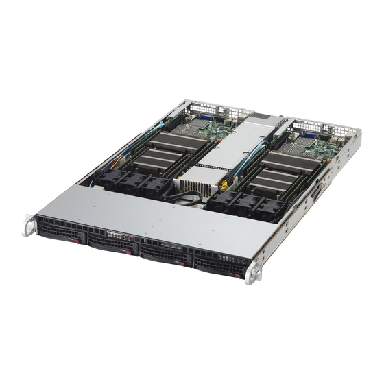
Chapter 1 Introduction Overview The SuperServer 6018R-TDTP/TDTPR is a high-end server comprised of two main subsystems: the SC815TQ-600CB/SC815TQ-R500CB 1U chassis and the X10DRD-LTP serverboard. Please refer to our website for information on operating systems that have been certified for use with the system (www.supermicro.com). -
Page 7: Serverboard Features
Serverboard Features Server Chassis Features At the heart of the SuperServer 6018R-TDTP/TDTPR lies the X10DRD-LTP, a dual The following is a general outline of the main features of the SC815TQ-600CB/ processor serverboard based on the Intel PCH C612 chipset. Below are the main SC815TQ-R500CB chassis. -
Page 8: Contacting Supermicro
Note: This is a general block diagram. Please see Chapter 5 for details. San Jose, CA 95131 U.S.A. Tel: +1 (408) 503-8000 Fax: +1 (408) 503-8008 Email: marketing@supermicro.com (General Information) X10DRD-i(N)TP/LTP VCCP0 12v VCCP1 12v VR12.5 VR12.5 support@supermicro.com (Technical Support) - Page 9 UPER ERVER 6018R-TDTP/TDTPR User's Manual Notes...
-
Page 10: Chapter 2 Server Installation
Server Installation Overview This chapter provides a quick setup checklist to get your SuperServer 6018R-TDTP/ TDTPR up and running. Following these steps in the order given should enable you to have the system operational within a minimum amount of time. -
Page 11: Warnings And Precautions
Chapter 2: Server Installation UPER ERVER 6018R-TDTP/TDTPR User's Manual Warnings and Precautions Rack Mounting Considerations • This product is not suitable for use with visual display work place devices Ambient Operating Temperature acccording to §2 of the the German Ordinance for Work with Visual Display Units. If installed in a closed or multi-unit rack assembly, the ambient operating tempera- ture of the rack environment may be greater than the ambient temperature of the Rack Precautions... -
Page 12: Installing The System Into A Rack
Chapter 2: Server Installation UPER ERVER 6018R-TDTP/TDTPR User's Manual Installing the System into a Rack Installing the Outer Rails Begin by measuring the distance from the front rail to the rear rail of the rack. Attach This section provides information on installing the 6018R-TDTP/TDTPR into a rack a short bracket to the front side of the right outer rail and a long bracket to the rear unit with the rack rails provided. -
Page 13: Installing The Server Into The Rack
Chapter 2: Server Installation UPER ERVER 6018R-TDTP/TDTPR User's Manual Installing the Server into the Rack Installing the Server into a Telco Rack You should now have rails attached to both the chassis and the rack unit. The next To install the 6018R-TDTP/TDTPR into a Telco type rack, use two L-shaped brackets step is to install the server into the rack. - Page 14 UPER ERVER 6018R-TDTP/TDTPR User's Manual Notes...
-
Page 15: Overview
Chapter 3: System Interface Chapter 3 System Interface Overview There are several LEDs on the control panel as well as others on the hard drive carriers to keep you constantly informed of the overall status of the system as well as the activity and health of specific components. -
Page 16: Control Panel Leds
(see Chapter 5). This LED will remain flashing or on as long as the indicated condition exists. Indicates IDE channel activity. On the SuperServer 6018R-TDTP/TDTPR, this light indicates SATA and/or DVD-ROM drive activity when flashing. -
Page 17: Drive Carrier Leds
UPER ERVER 6018R-TDTP/TDTPR User's Manual Hard Drive Carrier LEDs Each hard drive carrier has two LEDs. • Green: When illuminated, the green LED on the front of the drive carrier in- dicates drive activity. A connection to the SATA backplane enables this LED to blink on and off when that particular drive is being accessed. -
Page 18: Chapter 4 Standardized Warning Statements For Ac Systems
Only certified technicians should attempt to install or configure components. Read this appendix in its entirety before installing or configuring components in the Supermicro chassis. These warnings may also be found on our web site at http://www.supermicro.com/ about/policies/safety_information.cfm. Warning Definition Warning! This warning symbol means danger. - Page 19 Warning Statements for AC Systems UPER ERVER 6018R-TDTP/TDTPR User's Manual جسذٌة اصابة ًتتسبب ف حالة ٌوكي أى ًاًك ف خطز ًٌٌع هذا الزهز !تحذٌز Warnung الذوائز بالوخاطز الٌاجوة عي ي على علن ، ك هعذات تعول على أي قبل أى الكهزبائٍة...
-
Page 20: Installation Instructions
Chapter 4: Warning Statements for AC Systems UPER ERVER 6018R-TDTP/TDTPR User's Manual Installation Instructions Circuit Breaker Warning! Warning! Read the installation instructions before connecting the system to the power source. This product relies on the building's installation for short-circuit (overcurrent) 設置手順書... -
Page 21: Power Disconnection Warning
Chapter 4: Warning Statements for AC Systems UPER ERVER 6018R-TDTP/TDTPR User's Manual Warnung Das System muss von allen Quellen der Energie und vom Netzanschlusskabel في التي تم تثبيتها مه الدوائرالقصيرة الحمايت معداث يعتمد على هذا المنتج getrennt sein, das von den Spg.Versorgungsteilmodulen entfernt wird, bevor es المبنى... -
Page 22: Equipment Installation
Chapter 4: Warning Statements for AC Systems UPER ERVER 6018R-TDTP/TDTPR User's Manual Equipment Installation Waarschuwing Deze apparatuur mag alleen worden geïnstalleerd, vervangen of hersteld door geschoold en gekwalificeerd personeel. Warning! Only trained and qualified personnel should be allowed to install, replace, or service Restricted Area this equipment. -
Page 23: Battery Handling
Chapter 4: Warning Statements for AC Systems UPER ERVER 6018R-TDTP/TDTPR User's Manual Warnung אזור עם גישה מוגבלת Bei Einsetzen einer falschen Batterie besteht Explosionsgefahr. Ersetzen Sie die !אזהרה Batterie nur durch den gleichen oder vom Hersteller empfohlenen Batterietyp. יש להתקין את היחידה באזורים שיש בהם הגבלת גישה. הגישה ניתנת בעזרת Entsorgen Sie die benutzten Batterien nach den Anweisungen des Herstellers. -
Page 24: Redundant Power Supplies
Chapter 4: Warning Statements for AC Systems UPER ERVER 6018R-TDTP/TDTPR User's Manual Redundant Power Supplies امداد الطاقة بوحدات عدة اتصاالت جهاز ال يكون لهذا قد الكهرباء عن وحدة ال لعسل كافة االتصاالت يجب إزالة Warning! This unit might have more than one power supply connection. All connections must 경고! be removed to de-energize the unit. -
Page 25: Comply With Local And National Electrical Codes
Chapter 4: Warning Statements for AC Systems UPER ERVER 6018R-TDTP/TDTPR User's Manual Attention ¡Advertencia! Lorsque le système est en fonctionnement, des tensions électriques circulent sur La instalacion del equipo debe cumplir con las normas de electricidad locales y le fond de panier. Prendre des précautions lors de la maintenance. nacionales.Attention L'équipement doit être installé... -
Page 26: Hot Swap Fan Warning
Chapter 4: Warning Statements for AC Systems UPER ERVER 6018R-TDTP/TDTPR User's Manual 当您从机架移除风扇装置,风扇可能仍在转动。小心不要将手指、螺丝起子和其他 Warnung 物品太靠近风扇 Die Entsorgung dieses Produkts sollte gemäß allen Bestimmungen und Gesetzen des Landes erfolgen. 警告 ¡Advertencia! 當您從機架移除風扇裝置,風扇可能仍在轉動。小心不要將手指、螺絲起子和其他 物品太靠近風扇。 Al deshacerse por completo de este producto debe seguir todas las leyes y reglamentos nacionales. -
Page 27: Power Cable And Ac Adapter
UL ou CSA câbles certifiés qui ont UL ou CSA indiqué sur le code use of UL or CSA -certified cables (that have UL/CSA shown on the code) for any pour tous les autres appareils électriques que les produits désignés par Supermicro other electrical devices than products designated by Supermicro only. - Page 28 Elektrisch apparaat en veiligheidsinformatiebladen wet verbiedt het gebruik van UL of CSA gecertificeerde kabels die UL of CSA die op de code voor andere elektrische apparaten dan de producten die door Supermicro alleen. 4-20...
-
Page 29: Chapter 5 Advanced Serverboard Setup
Chapter 5: Advanced Serverboard Setup Chapter 5 Advanced Serverboard Setup This chapter covers the steps required to install processors and heatsinks to the X10DRD-LTP serverboard, connect the data and power cables and install add-on cards. All serverboard jumpers and connections are described and a layout and quick reference chart are included in this chapter. -
Page 30: Processor And Heatsink Installation
CPU so • that all keys and edges will fit Refer to the Supermicro website for updates on CPU support. the socket. Installing a CPU 1. There are two levers on the LGA 2011 socket. -
Page 31: Installing A Passive Cpu Heatsink
Chapter 5: Advanced Serverboard Setup UPER ERVER 6018R-TDTP/TDTPR User's Manual Installing a Passive CPU Heatsink 1. Do not apply any thermal grease to the heatsink or the CPU die -- the re- Gently close quired amount has already been applied. the load plate. -
Page 32: Connecting Cables
Chapter 5: Advanced Serverboard Setup UPER ERVER 6018R-TDTP/TDTPR User's Manual Connecting Cables Figure 5-2. Front Control Panel Header Pins (JF1) Now that the processors are installed, the next step is to connect the cables to the serverboard. These include the data (ribbon) cables for the peripherals and control Power Button Ground panel and the power cables. -
Page 33: Installing Memory
ERVER 6018R-TDTP/TDTPR User's Manual Installing Memory Processor & Memory Module Population Configuration For the memory to work properly, follow the tables below. Note: Check the Supermicro website for recommended memory modules. Processors and their Corresponding CAUTION Memory Modules Exercise extreme care when installing or removing DIMM modules... -
Page 34: Adding Pci Cards
Chapter 5: Advanced Serverboard Setup UPER ERVER 6018R-TDTP/TDTPR User's Manual Adding PCI Cards Serverboard Details Figure 5-5. SUPER X10DRD-LTP Layout PCI Expansion Slots One RSC-RR1U-E8 riser card is used to support a standard size expansion (add- LAN2 USB0/1 LAN1 SFP2 JUSBRJ45 SFP1 on) card to the system. -
Page 35: X10Drd-Ltp Quick Reference
Chapter 5: Advanced Serverboard Setup UPER ERVER 6018R-TDTP/TDTPR User's Manual Connector Definitions X10DRD-LTP Quick Reference ATX Power 24-pin Connector Pin Definitions (JPW1) Jumper Description Default Setting Pin# Definition Pin # Definition Power Connectors JBT1 Clear CMOS See Section 5-9 +3.3V +3.3V A 24-pin main ATX power supply connec- C1/JI... - Page 36 Chapter 5: Advanced Serverboard Setup UPER ERVER 6018R-TDTP/TDTPR User's Manual NIC1/NIC2 LED Indicators Power Button NIC1/2 LED Pin Definitions (JF1) The NIC (Network Interface Controller) The Power Button connection is located Pin# Definition LED connection for LAN port 1 is located on pins 1 and 2 of JF1.
- Page 37 Pin # Definition Pin # Definition guide posted on our website @ http:// The JTPM1 header is used to connect a LCLK www.supermicro.com. Trusted Platform Module (TPM), available LFRAME# <(KEY)> separately from a third-party vendor. A LRESET# +5V (X) TPM is a security device that allows en-...
-
Page 38: Jumper Settings
Chapter 5: Advanced Serverboard Setup UPER ERVER 6018R-TDTP/TDTPR User's Manual Jumper Settings T-SGPIO 0/1 Headers Serial_Link-SGPIO Explanation of Jumpers Two T-SGPIO (Serial-Link General Pin Definitions Purpose Input/Output) headers are Pin# Definition Definition To modify the operation of the serverboard, included to communicate with the en- jumpers can be used to choose between Connector closure management chip in the system. -
Page 39: 5-10 Onboard Indicators
Chapter 5: Advanced Serverboard Setup UPER ERVER 6018R-TDTP/TDTPR User's Manual 5-10 Onboard Indicators C Bus to PCI-Express Slots Use Jumpers JI C1 and JI C2 to connect SFP+/LAN 1 & 2 C for PCI-E slots SFP+/LAN1/LAN2 LEDs Activity LEDs Status Jumper Settings the System Management Bus (I C) to... -
Page 40: 5-11 Sata Drive Ports
UPER ERVER 6018R-TDTP/TDTPR User's Manual 5-11 SATA Drive Ports 5-12 Installing Drivers The Supermicro FTP site contains drivers and utilities for your system at ftp://ftp. supermicro.com. Some of these must be installed, such as the chipset driver. SATA Ports After accessing the FTP site, go into the CDR_Images directory and locate the ISO file for your serverboard. -
Page 41: Superdoctor® 5
5-13 Onboard Battery SuperDoctor® 5 The Supermicro SuperDoctor 5 is a program that functions in a command-line or Care must be taken to assure that the chassis cover is in place when the system web-based interface in Windows and Linux operating systems. The program moni- is operating to assure proper cooling. - Page 42 UPER ERVER 6018R-TDTP/TDTPR User's Manual Notes 5-26...
-
Page 43: Chapter 6 Advanced Chassis Setup
Chapter 6: Advanced Chassis Setup Chapter 6 Advanced Chassis Setup This chapter covers the steps required to install components and perform mainte- nance on the SC815TQ-600CB/SC815TQ-R500CB chassis. For component instal- lation, follow the steps in the order given to eliminate the most common problems encountered. -
Page 44: Control Panel
2. Unplug the fan cable from the serverboard and remove the failed blower fan from the chassis. I/O Ports 3. Replace the failed fan with an identical 4-cm fan (available from Supermicro). Control Panel 4. Push the new fan into the vacant space in the housing while making sure the... -
Page 45: Drive Bay Installation/Removal
Chapter 6: Advanced Chassis Setup UPER ERVER 6018R-TDTP/TDTPR User's Manual Figure 6-2. System Cooling Fans Figure 6-3. Removing the Front Bezel 1. Unlock 2. Press release knob 3. Remove bezel assembly Accessing the Drive Bays Drive Bay Installation/Removal SATA Drives: Because of their hotswap capability, you do not need to access the inside of the chassis or power down the system to install or replace SATA drives. -
Page 46: Hard Drive Installation
Warning: Enterprise level hard disk drives are recommended for use in Supermicro chassis and servers. For information on recommended HDDs, visit the Supermicro... -
Page 47: Dvd-Rom Drive Installation
DVD-ROM Drive Installation The top cover of the chassis must be opened to gain full access to the DVD-ROM The SuperServer 6018R-TDTP has a single 600 watt power supply while the 6018R- drive bay. The 6018R-TDTP/TDTPR accomodates only slim-line DVD-ROM drives. -
Page 48: 6018R-Tdtpr
A power fail condition will be displayed on the front control panel until the failed unit has been replaced. Replacement units can be ordered directly from Supermicro. The power supply units have a hot-swap capability, meaning you can replace the failed unit without powering down the system. - Page 49 UPER ERVER 6018R-TDTP/TDTPR User's Manual Notes 6-12...
-
Page 50: Chapter 7 Bios
When an option is selected in the left frame, it is highlighted in white. Often a text message will accompany it. Note: the AMI BIOS has default text messages built in. Supermicro retains the option to include, omit, or change any of these text messages. -
Page 51: How To Start The Setup Utility
Flashing the wrong BIOS can cause irreparable damage to the system. In no event Supermicro X10DRD-i shall Supermicro be liable for direct, indirect, special, incidental, or consequential dam- ages arising from a BIOS update. If you have to update the BIOS, do not shut down BIOS Version: This item displays the version of the BIOS ROM used in the or reset the system while the BIOS is updating. -
Page 52: Advanced Setup Configurations
Chapter 7: BIOS UPER ERVER 6018R-TDTP/TDTPR User's Manual Advanced Setup Configurations Wait For 'F1' If Error Select Enabled to force the system to wait until the 'F1' key is pressed if an error Use the arrow keys to select Advanced setup and press <Enter> to access the occurs. - Page 53 Chapter 7: BIOS UPER ERVER 6018R-TDTP/TDTPR User's Manual CPU Configuration Execute Disable Bit (Available if supported by the OS & the CPU) Select Enable to enable the Execute-Disable Bit technology which will allow the This submenu displays the information of the CPU as detected by the BIOS. It also processor to designate areas in the system memory where an application code allows the user to configuration CPU settings.
- Page 54 Chapter 7: BIOS UPER ERVER 6018R-TDTP/TDTPR User's Manual IIO2 Configuration tions, creating multiple "virtual" systems in one physical computer. The options are Enable and Disable. CPU2 SLOT7 PCI-E 3.0 x8 Note: If a change is made to this setting, you will need to reboot the Use this feature to set the PCI-Exp bus speed for the slot specified above.
- Page 55 Chapter 7: BIOS UPER ERVER 6018R-TDTP/TDTPR User's Manual QPI (Quick Path Interconnect) Configuration Memory Configuration Integrated Memory Controller (IMC) The following QPI information will be displayed: • Enforce POR Number of CPU Select Enable to enforce POR restrictions on DDR4 frequency and voltage •...
- Page 56 Chapter 7: BIOS UPER ERVER 6018R-TDTP/TDTPR User's Manual • P1-DIMMD1 correctable error, the error is corrected and sent to the requestor (the original source). Memory is updated as well. Select Enable to use Demand Scrubbing • P2-DIMME1 for ECC memory correction. The options are Enable and Disable. •...
- Page 57 Chapter 7: BIOS UPER ERVER 6018R-TDTP/TDTPR User's Manual SATA Configuration Port 0 ~ Port 5 SATA Device Type Use this item to specify if the SATA port specified by the user should be con- When this submenu is selected, AMI BIOS automatically detects the presence of nected to a Solid State drive or a Hard Disk Drive.
- Page 58 Chapter 7: BIOS UPER ERVER 6018R-TDTP/TDTPR User's Manual • Software Preserve Support sSATA Port 0~ Port 3 This item displays the information detected on the installed on the sSATA port. Port 0~ Port 5 specified by the user. • Select Enabled to enable a SATA port specified by the user. The options are Model number of drive and capacity Disabled and Enabled.
- Page 59 Chapter 7: BIOS UPER ERVER 6018R-TDTP/TDTPR User's Manual *If the item above "Configure sSATA as" is set to RAID, the following items Port 0 ~ Port 3 sSATA Device Type will display: Use this item to specify if the sSATA port specified by the user should be con- nected to a Solid State drive or a Hard Disk Drive.
- Page 60 Chapter 7: BIOS UPER ERVER 6018R-TDTP/TDTPR User's Manual SR-IOV (Available if the system supports Single-Root Virtualization) Onboard LAN1 Option ROM/Onboard LAN2 Option ROM Select Enabled for Single-Root IO Virtualization support. The options are Enabled Use this option to select the type of device installed in LAN Port1 or LAN Port2 and Disabled.
- Page 61 Chapter 7: BIOS UPER ERVER 6018R-TDTP/TDTPR User's Manual Device Mode is odd. Select None if you do not want to send a parity bit with your data bits in transmission. Select Mark to add a mark as a parity bit to be sent along with Use this feature to configure SUART clock source settings.
- Page 62 Chapter 7: BIOS UPER ERVER 6018R-TDTP/TDTPR User's Manual SOL/COM2 Flow Control Use this feature to set the flow control for Console Redirection to prevent data Console Redirection loss caused by buffer overflow. Send a "Stop" signal to stop sending data when Select Enabled to use the SOL port for Console Redirection.
- Page 63 Chapter 7: BIOS UPER ERVER 6018R-TDTP/TDTPR User's Manual Data Bits, Parity, Stop Bits Serial Port for Out-of-Band Management/Windows Emergency Management Services (EMS) ACPI Settings The submenu allows the user to configure Console Redirection settings to sup- port Out-of-Band Serial Port management. WHEA Support EMS Console Redirection Select Enabled to support the Windows Hardware Error Architecture (WHEA) plat-...
-
Page 64: Event Logs
Chapter 7: BIOS UPER ERVER 6018R-TDTP/TDTPR User's Manual Pending Operation Event Logs Use this item to schedule a TPM-related operation to be performed by a security Use this feature to configure Event Log settings. device for system data integrity. Your system will reboot to carry out a pending TPM operation. -
Page 65: Ipmi
Chapter 7: BIOS UPER ERVER 6018R-TDTP/TDTPR User's Manual Erasing Settings IPMI Erase Event Log Use this feature to configure Intelligent Platform Management Interface (IPMI) settings. Select Enabled to erase all error events in the SMBIOS (System Management BIOS) log before an event logging is initialized at bootup. The options are No, Yes, Next Reset and Yes, Every Reset. - Page 66 Chapter 7: BIOS UPER ERVER 6018R-TDTP/TDTPR User's Manual When SEL is Full Station MAC Address This feature allows the user to determine what the BIOS should do when the sys- This item displays the Station MAC address for this computer. Mac addresses are tem event log is full.
-
Page 67: Security Settings
Chapter 7: BIOS UPER ERVER 6018R-TDTP/TDTPR User's Manual Boot Settings Security Settings Use this feature to configure Boot Settings: This menu allows the user to configure the following security settings for the system. Setup Prompt Timeout This feature allows the user to determine how long the system should wait for the Password Check setup activation key before it boots up. - Page 68 Chapter 7: BIOS UPER ERVER 6018R-TDTP/TDTPR User's Manual • NETWORK Disk Drive BBS Priorities Dual Boot Order #8 • Legacy Boot Order #1 • Dual Boot Order #9 • UEFI Application Boot Priorities Dual Boot Order #10 • UEFI Boot Order #1 •...
-
Page 69: Save & Exit
Chapter 7: BIOS UPER ERVER 6018R-TDTP/TDTPR User's Manual Save & Exit Save As User Defaults To set this feature, select Save as User Defaults from the Exit menu and press <En- Select the Save & Exit tab from the BIOS setup screen to configure the settings ter>. - Page 70 UPER ERVER 6018R-TDTP/TDTPR User's Manual Notes 7-40...
-
Page 71: Appendix A Bios Error Beep Codes
Appendix A: BIOS Error Beep Codes Appendix A BIOS Error Beep Codes During the POST (Power-On Self-Test) routines, which are performed upon each system boot, errors may occur. Non-fatal errors are those which, in most cases, allow the system to continue to boot. - Page 72 UPER ERVER 6018R-TDTP/TDTPR User's Manual Notes...
-
Page 73: Appendix B System Specifications
Appendix B: System Specifications Appendix B System Specifications Processors Dual Intel ® Xeon ® E5-2600 v3 Series v3/v4 processors in R3 LGA 2011 sockets Note: Please refer to our web site for a complete listing of supported processors. Chipset Intel PCH C612 Memory Capacity Eight DIMM sockets that can support up to 1 TB of LRDIMM (Load Reduced DIMM) or up to 512 GB of ECC RDIMM (Registered DIMM) DDR4-... - Page 74 Disclaimer (continued from front) Non-operating Relative Humidity: 5% to 95% (non-condensing) The products sold by Supermicro are not intended for and will not be used in life support systems, medical equipment, nuclear facilities or systems, aircraft, aircraft devices, aircraft/emergency com- munication devices or other critical systems whose failure to perform be reasonably expected to result in significant injury or loss of life or catastrophic property damage.
- Page 75 UPER ERVER 6018R-TDTP/TDTPR User's Manual Notes...
Need help?
Do you have a question about the SUPERSERVER 6018R-TDTP and is the answer not in the manual?
Questions and answers