Table of Contents
Advertisement
Quick Links
Advertisement
Table of Contents
Troubleshooting

Related Manuals for Hach 5410001


Summary of Contents for Hach 5410001
- Page 1 DOC023.53.80422 SP-510 03/2022, Edition 13 User Manual...
-
Page 3: Table Of Contents
Table of Contents Section 1 Specifications ..................3 Section 2 General information ................4 2.1 Safety information ....................4 2.1.1 Use of hazard information ................5 2.1.2 Precautionary labels ................... 5 2.1.3 Compliance and certification ..............5 2.2 Product overview ....................6 2.3 Product components ..................... - Page 4 Table of Contents 8.11 Replace the fuse ....................21 Section 9 Troubleshooting ................. 21 9.1 Troubleshooting for a hard reading ..............22 Section 10 Replacement parts and consumables ........23 Index ..........................25...
-
Page 5: Section 1 Specifications
Section 1 Specifications Specifications are subject to change without notice. General specifications Specification Details Dimensions (W x D x H) 42 x 31.5 x 18 cm (16.5 x 12.5 x 7 in.) Enclosure rating IP62 Weight 11.3 kg (25 lbs) Installation environment Indoor Mount... -
Page 6: Section 2 General Information
Specification Details Sample flow rate to sample 50 to 500 mL/minute flow rate necessary (250 mL/minute conditioning recommended) Inlet pressure to instrument 1 to 5 psig (0.07 to 0.34 bar), 1.5 psig (0.1 bar) is optimum, > 5 psig (0.34 bar) can cause sample tubing failure Inlet pressure to sample 1.5 psig to 75 psig (0.1 to 5.2 bar) conditioning... -
Page 7: Use Of Hazard Information
2.1.1 Use of hazard information D A N G E R Indicates a potentially or imminently hazardous situation which, if not avoided, will result in death or serious injury. W A R N I N G Indicates a potentially or imminently hazardous situation which, if not avoided, could result in death or serious injury. -
Page 8: Product Overview
Canadian Radio Interference-Causing Equipment Regulation, ICES-003, Class A: Supporting test records reside with the manufacturer. This Class A digital apparatus meets all requirements of the Canadian Interference-Causing Equipment Regulations. Cet appareil numérique de classe A répond à toutes les exigences de la réglementation canadienne sur les équipements provoquant des interférences. -
Page 9: Product Components
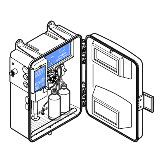
Figure 1 Product overview 1 Power switch 7 Keypad 2 Power access port 8 Pump/valve module 3 Relay and alarm contact access port 9 Indicator and reagent bottles 4 Air purge (optional) 10 Sample inlet 5 Access cover 11 Enclosure drain 6 Colorimeter 12 Sample drain 2.3 Product components... -
Page 10: Section 3 Installation
Figure 2 Product components 1 SP-510 Hardness Monitor 5 Indicator solution 2 Installation kit 6 Magnesium sulfate solution ® 3 Maintenance kit 7 TitraVer (EDTA) hardness titrant 4 Buffer solution Section 3 Installation D A N G E R Electrocution hazard. Always remove power to the instrument before making electrical connections. - Page 11 Figure 3 Dimensions for wall installation Figure 4 Door clearance English 9...
-
Page 12: Plumb The Instrument
3.2 Plumb the instrument C A U T I O N Fire hazard. This product is not designed for use with flammable liquids. C A U T I O N Chemical hazard. If there is a leak in the fluid system, hazardous substances may leak out of the lower enclosure. -
Page 13: Install The Pump Valve Pressure Plate
Keep the sample lines as short as possible to prevent the accumulation of bottom sediment. The sediment can absorb some of the analyte from the sample and cause low readings. The sediment can later release the analyte and cause high readings. This exchange with the sediment also causes a delayed response when the analyte concentration in the sample increases or decreases. -
Page 14: Electrical Installation
Figure 7 Sample flow through the conditioning kit 1 Sample flow 4 Bypass tee, unfiltered 7 Unfiltered-sample ball valve sample (shown open) 2 Bypass flow 5 Flow observation point 8 Low-flow valve option 3 Drainage flow 6 Filtered-sample bypass ball 9 High-flow valve option valve (shown open) 3.3 Electrical installation... -
Page 15: Electrical Connections For Conduit
Figure 8 Access cover removal 3.3.2 Electrical connections for conduit D A N G E R Electrocution hazard. Use only fittings that have the specified environmental enclosure rating. Obey the requirements in the Specifications section. D A N G E R Electrocution hazard. -
Page 16: Wiring For Power
3.3.3 Wiring for power To connect the instrument to power, refer to Figure 10 Table Figure 10 Power connection 1 Voltage switch (in 115 V position) 3 AC power connector 2 Voltage switch (in 230 V position) 4 Fuses (F1 and F2) Table 1 Terminal wiring Wire color code Protective earth... -
Page 17: Install The Buffer Solution
Figure 11 shows the alarm relay contacts connected to the terminal strip with normally open and normally closed terminations. Terminals are unpowered and rated for 5 A at 100–240 VAC resistive load. The relay connector accepts 18–12 AWG (0.75–1.0 mm ) wire. -
Page 18: Install The Stir Bar
Figure 12 Install the buffer and indicator reagents 1 Indicator reagent tube label and bottle 2 Buffer tube label and bottle 3.6 Install the stir bar A stir bar is included in the installation kit. Install the stir bar in the colorimeter sample cell for correct operation. -
Page 19: Section 5 Startup
Figure 14 SP-510 keypad Table 3 Keypad description Key Function Description HARD LED The monitor found hardness in the water. The status indicator light is red. SOFT LED The monitor is in operation and no hardness shows. The status indicator light is green. -
Page 20: Section 6 Calibration
6. Tighten the screws on the pump pinch plate. Do not overtighten. 7. Remove the syringe from the tubing and connect the fitting on the colorimeter. Section 6 Calibration C A U T I O N Chemical exposure hazard. Obey laboratory safety procedures and wear all of the personal protective equipment appropriate to the chemicals that are handled. -
Page 21: Maintenance Schedule
8.1 Maintenance schedule Table 4 shows the recommended schedule of maintenance tasks. Facility requirements and operating conditions can increase the frequency of some tasks. Table 4 Maintenance schedule Task 2 months 3 months 6 months 1 year As necessary Replace the reagent on page 19 Replace the pump tubes on page 20... -
Page 22: Change The Alarm Trip Point
1. Discard the old containers with remaining contents in compliance with MSDS and regulatory requirements. 2. Install the new bottles. Refer to Install the buffer solution on page 15 and Install the indicator solution on page 15. 8.6 Change the alarm trip point Install the applicable buffer and indicator solution to change the alarm trip point to a different hardness level. -
Page 23: Replace The Fuse
8.11 Replace the fuse D A N G E R Electrocution hazard. Remove power from the instrument before doing maintenance or service activities. D A N G E R Fire hazard. Use the same type and current rating to replace fuses. Remove the two fuses (F1 and F2) and replace them with two new fuses with the same specifications, T, 1.25 A, 250 V. -
Page 24: Troubleshooting For A Hard Reading
Problem Possible cause Solution The HARD LED is flashing. The instrument could not Contact technical support. save the calibration information. The instrument could not save the disabled alarm status. The SOFT LED is flashing The optical path has a • Let the instrument complete the continuously for more than blockage or the optical cycle. -
Page 25: Section 10 Replacement Parts And Consumables
Cause Solution The instrument does not Remove the two reagent lines from the Y connector. Only one drop receive any buffer or of reagent comes out per cycle. If no reagent comes out, examine indicator solution. the pressure plate. Make sure that the pinch block is not overtightened and the reagent lines are not pinched. - Page 26 Replacement parts (continued) Description Item no. Stir coil 5411100 Thumb screw to hold pressure plate (2x) 5410100 Tubing, 0.16 cm (0.0625 in.) ID, white 4271700 Tubing, 0.11 cm (0.043 in.) ID, brown 5412100 Y fitting/strainer, 40 mesh 4661600 Accessories Description Item no.
-
Page 27: Index
Index Air purge ............10 Keypad ............16 Alarm .............. 14 Alarm trip point ..........20 Navigation ............16 Buffer solution ..........15 Pressure plate ..........11 Calibration ............18 Chemistry ............22 Colorimeter ............. 20 Reagent ............ 15, 19 Reagent line ........... - Page 30 Tel. +49 (0) 2 11 52 88-320 SWITZERLAND Fax (970) 669-2932 Fax +49 (0) 2 11 52 88-210 Tel. +41 22 594 6400 orders@hach.com info-de@hach.com Fax +41 22 594 6499 www.hach.com www.de.hach.com © Hach Company/Hach Lange GmbH, 2013, 2014, 2016–2018, 2020–2022. All rights reserved.
Need help?
Do you have a question about the 5410001 and is the answer not in the manual?
Questions and answers