Hach SP-510 User Manual
Hardness analyzer
Hide thumbs
Also See for SP-510:
- Basic user manual (188 pages) ,
- Instrument manual (61 pages) ,
- User manual (30 pages)
Table of Contents
Advertisement
Advertisement
Table of Contents

Subscribe to Our Youtube Channel
Related Manuals for Hach SP-510


Summary of Contents for Hach SP-510
- Page 1 DOC023.53.80422 SP-510 01/2017, Edition 8 User Manual...
-
Page 3: Table Of Contents
Table of Contents Specifications ......................3 General information ....................4 Safety information ......................4 Use of hazard information ..................4 Precautionary labels ..................... 5 Certification ......................5 Product overview ......................6 Product components ....................7 Installation ........................8 Install the instrument ....................8 Plumb the instrument .................... - Page 4 Table of Contents Replace the fuse ......................20 Troubleshooting ....................... 21 Troubleshooting for a hard reading ................21 Replacement parts and consumables ............22 Index ..........................25...
-
Page 5: Specifications
Specifications Specifications are subject to change without notice. General specifications Specification Details Dimensions (W x D x H) 42 x 31.5 x 18 cm (16.5 x 12.5 x 7 in.) Enclosure rating IP62 Weight 11.3 kg (25 lbs) Installation environment Indoor Mount Wall... -
Page 6: General Information
Specification Details Drain fitting Hose barb for 12.7 mm (0.5 in.) ID flexible tubing Sample temperature range 5 to 40 °C (41 to 104 °F) Certifications CE, cETLus Warranty 1 year (EU: 2 years) Trip point specifications Alarm trip point Minimum trip value Maximum trip value Temperature influence on trip point... -
Page 7: Precautionary Labels
N O T I C E Indicates a situation which, if not avoided, may cause damage to the instrument. Information that requires special emphasis. Precautionary labels Read all labels and tags attached to the instrument. Personal injury or damage to the instrument could occur if not observed. -
Page 8: Product Overview
™ The SP-510 Hardness Monitor continuously measures water softener levels to find hardness breakthroughs based on softener exhaustion. The monitor is used in commercial and industrial water applications. -
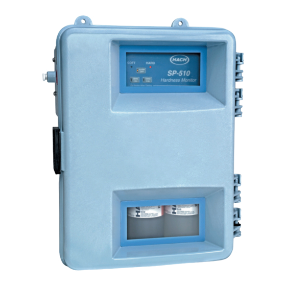
Page 9: Product Components
Figure 1 Product overview 1 Power switch 7 Keypad 2 Power access port 8 Pump/valve module 3 Relay and alarm contact access port 9 Indicator and reagent bottles 4 Air purge (optional) 10 Sample inlet 5 Access cover 11 Enclosure drain 6 Colorimeter 12 Sample drain Product components... -
Page 10: Installation
Figure 2 Product components 1 SP-510 Hardness Monitor 5 Indicator solution 2 Installation kit 6 Magnesium sulfate solution ® 3 Maintenance kit 7 TitraVer (EDTA) hardness titrant 4 Buffer solution Installation D A N G E R Electrocution hazard. Always remove power to the instrument before making electrical connections. -
Page 11: Plumb The Instrument
Figure 3 Dimensions for wall installation Figure 4 Door clearance Plumb the instrument C A U T I O N Fire hazard. This product is not designed for use with flammable liquids. English 9... -
Page 12: Connect The Air Purge (Optional)
C A U T I O N Chemical hazard. If there is a leak in the fluid system, hazardous substances may leak out of the lower enclosure. Put the supplied reagent bottle tray or a bucket under the drain to catch any spills. C A U T I O N Chemical exposure hazard. -
Page 13: Install The Pump Valve Pressure Plate
Figure 5 Sampling methods 1 Air 2 Sample flow Install the pump valve pressure plate The pressure plate and screws are supplied with the installation kit. Remove the tape from the pump tubes before installation. Make sure to turn the screws in small increments and move from one screw to the other so that the plate is pulled down equally. -
Page 14: Electrical Installation
Figure 7 Sample flow through the conditioning kit 1 Sample flow 4 Bypass tee, unfiltered sample 7 Unfiltered-sample ball valve (shown open) 2 Bypass flow 5 Flow observation point 8 Low-flow valve option 3 Drainage flow 6 Filtered-sample bypass ball 9 High-flow valve option valve (shown open) Electrical installation... -
Page 15: Electrical Connections For Conduit
Figure 8 Access cover removal Electrical connections for conduit D A N G E R Electrocution hazard. Use only fittings that have the specified environmental enclosure rating. Obey the requirements in the Specifications section. D A N G E R Electrocution hazard. -
Page 16: Wiring For Power
Wiring for power To connect the instrument to power, refer to Figure 10 Table Figure 10 Power connection 1 Voltage switch (in 115 V position) 3 AC power connector 2 Voltage switch (in 230 V position) 4 Fuses (F1 and F2) Table 1 Terminal wiring Wire color code Protective earth ground... -
Page 17: Install The Buffer Solution
The relay connector accepts 18–12 AWG (0.75–1.0 mm ) wire. Select the necessary wire gage that operates with the application. A wire gauge less than 18 AWG (0.75 mm ) is not recommended. Figure 11 Alarm connections Table 2 Relay wiring Terminal block Terminal 1 Terminal 2... -
Page 18: Install The Stir Bar
Refer to Figure 14 and to Table 3 for the keypad description and navigation information. Figure 14 SP-510 keypad Table 3 Keypad description Key Function Description HARD LED The monitor found hardness in the water. The status indicator light is red. -
Page 19: Startup
Table 3 Keypad description (continued) Key Function Description HARD CAL Completes a hard calibration. Refer to Calibration on page 17. The status indicator light is yellow. ZERO CAL Completes a zero-point calibration. Refer to Calibration on page 17. The status indicator light is yellow. -
Page 20: Operation
3. When the hard cal LED flashes, add two drops of Magnesium Standard Solution into the colorimeter. 4. When the LED stops flashing and is on continuously, wait for the cycle to complete. At the end of the cycle, the LED sets to off to show a successful calibration. 5. -
Page 21: Clean The Instrument
Clean the instrument Clean the exterior of the instrument with a moist cloth and a mild soap solution and then wipe the instrument dry. Clean the instrument interior C A U T I O N Chemical exposure hazard. Obey laboratory safety procedures and wear all of the personal protective equipment appropriate to the chemicals that are handled. -
Page 22: Replace The Tubing
Replace the tubing The manufacturer recommends that one tube is replaced at a time. Refer to the documentation supplied with the maintenance kit. Clean the colorimeter W A R N I N G Chemical exposure hazard. Obey laboratory safety procedures and wear all of the personal protective equipment appropriate to the chemicals that are handled. -
Page 23: Troubleshooting
Remove the two fuses (F1 and F2) and replace them with two new fuses with the same specifications, T, 1.25 A, 250 V. The same fuse rating is used for the 115 V and for the 230 V operation. Refer to Figure 10 on page 14. -
Page 24: Replacement Parts And Consumables
Cause Solution If the flow is too low, the Make sure to set the flow rate to 200 mL/minute. sample cell does not flush completely all the color out of the colorimeter. This causes a zero reading. If the flow is too high, some of the water will bypass the pinch block and cause the color to be diluted. - Page 25 Replacement parts (continued) Description Item no. Colorimeter drain plug 5103600 Follower block, reagent 4274100 Follower block, sample 4274200 Fuse (T, 1.25 A, 250 V) UL/CSA/CE accepted 5516700 4350800 LED housing, lower 5412700 LED housing, upper 5412800 Maintenance kit 5516500 Installation kit 5516400 Motor assembly 5411900...
- Page 26 Buffer and indicator solution for the applicable trip point Trip point Buffer item no. Indicator item no. 0.3 mg/L 2768549 2794649 1 mg/L 2768549 2769049 2 mg/L 2768549 2769149 5 mg/L 2768549 2769249 10 mg/L 2768649 2769249 20 mg/L 2768749 2769249 50 mg/L 2768849...
-
Page 27: Index
Index Air purge ..............10 Alarm ................. 14 Alarm trip point ............19 Navigation ..............16 Buffer solution ............15 Pressure plate ............11 Calibration ..............17 Chemistry ..............21 Reagent ............... 15, 19 Colorimeter ..............20 Reagent line .............. 21 Relay ................. - Page 30 Tel. +49 (0) 2 11 52 88-320 SWITZERLAND Fax (970) 669-2932 Fax +49 (0) 2 11 52 88-210 Tel. +41 22 594 6400 orders@hach.com info-de@hach.com Fax +41 22 594 6499 www.hach.com www.de.hach.com © Hach Company/Hach Lange GmbH, 2013, 2014, 2016–2017. All rights reserved. Printed in U.S.A.
Need help?
Do you have a question about the SP-510 and is the answer not in the manual?
Questions and answers