Table of Contents
Advertisement
TRANSLATION OF ORIGINAL OPERATING AND
INSTRUCTION MANUAL
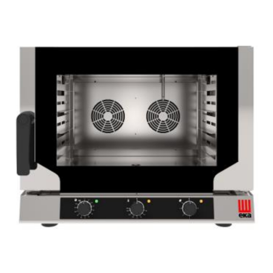
NEXT OVEN
EKF 412 NALU - EKF 423 NP – EKF 423 NUP – EKF 423 NM – EKF 423 N
EKF 423 NU - EKF 423 NUD
EKF 364 NUD – EKF 311 NUD
EKF 464 N – EKF 416 N – EKF 411 N
EKF 464.3 NGRILL – EKF 416.3 NGRILL – EKF 411.3 NGRILL
EKF 464 NUD – EKF 416 NUD – EKF 411 NUD
EKF 464 NALUD – EKF 416 NALUD – EKF 411 NALUD
EKF 464 NP – EKF 416 NP - EKF 464 NALP – EKF 416 NALP
Advertisement
Table of Contents


Need help?
Do you have a question about the EKF 412 NALU and is the answer not in the manual?
Questions and answers