
Related Manuals for Taurus SEBR7132


Summary of Contents for Taurus SEBR7132
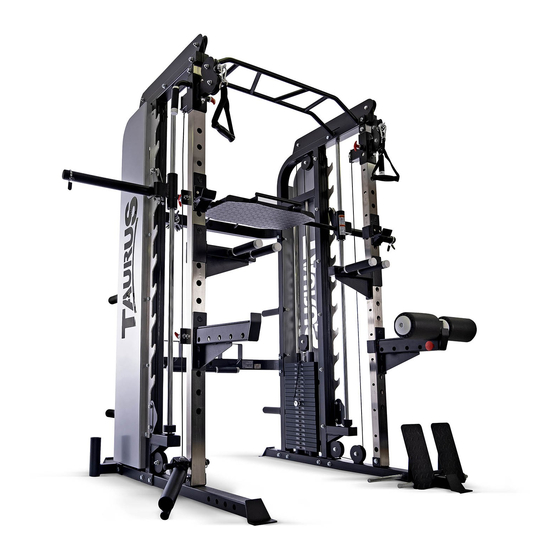
- Page 1 Assembly and Operating Instructions ~ 330 Min. 480 kg L 154 | W 220 | H 214 SEBR7132.01.01 SKU: SEBR7132 / SEBR7139 Taurus Elite Trainer...
- Page 2 Elite Trainer...
-
Page 3: Table Of Contents
Content GENERAL INFORMATION Technical Data Personal Safety Set-Up Place ASSEMBLY General Instructions Scope of Delivery Assembly Optional Jammer Arms STORAGE AND TRANSPORT General Instructions TROUBLESHOOTING, CARE AND MAINTENANCE General Instructions Faults and Fault Diagnosis Maintenance and Inspection Calendar DISPOSAL RECOMMENDED ACCESSORIES ORDERING SPARE PARTS Serial Number and Model Name Parts List: Smith Machine... - Page 4 Elite Trainer...
- Page 5 With Taurus® fitness equipment, the focus is on what sport is all about: maximum performance! Therefore, the equipment is developed in close consultation with athletes and sports scientists.
- Page 6 ABOUT THIS MANUAL Please carefully read the entire manual before installation and first use. The manual will help you to quickly set up the system and explains how to safely use it. Make sure that all persons exercising with the equipment (especially children and persons with physical, sensory, mental or motor disabilities) are informed about this manual and its contents in advance.
-
Page 7: General Information
GENERAL INFORMATION Technical Data Weight and Dimensions Article weight (gross, incl. packaging): 510 kg / 1124 lbs Article weight (net, without packaging): 480 kg / 1058 lbs Packaging dimensions (L x W x H): approx. 225 cm x 94 cm x 44 cm Set up dimensions (L x W x H): approx. -
Page 8: Personal Safety
Personal Safety DANGER ⚠ Before you start using the equipment, you should consult your physician that this type of exercise is suitable for you from a health perspective. Particularly affected are persons who: have a hereditary disposition to high blood pressure or heart disease, are over the age of 45, smoke, have high cholesterol values, are overweight and/or have not exercised regularly in the past year. -
Page 9: Set-Up Place
Set-Up Place WARNING ⚠ Do not place the equipment in main corridors or escape routes. ⚠ CAUTION Choose a location in which to place the equipment such that there is enough free space/ clearance to the front, the rear and to the sides of the equipment. The training room should be well ventilated during training and not be exposed to any draughts. -
Page 10: Assembly
ASSEMBLY General Instructions ⚠ DANGER Do not leave any tools, packaging materials such as foils or small parts lying around, as otherwise there is a danger of suffocation for children. Keep children away from the equipment during assembly. ⚠ WARNING Pay attention to the instructions attached to the equipment in order to reduce the risk of injuries. -
Page 11: Scope Of Delivery
Scope of Delivery The scope of delivery consist of the following parts. At the beginning, check whether all parts and tools belonging to the device are included in the scope of delivery and whether damage has occurred. In the event of complaints, the contractual partner must be contacted directly. CAUTION ⚠... - Page 12 Elite Trainer...
-
Page 13: Assembly
Assembly Before assembly, take a close look at the individual assembly steps shown and carry out the assembly in the order given. NOTICE First loosely screw all parts together and check that they fit properly. Tighten the screws using the tool only when you are instructed to do so. If you have difficulty recognising the graphics, we recommend that you open and/or download the PDF instructions stored in the webshop on your end device (e.g. - Page 14 Step 2: Connecting both Main Frames Connect the left and right part of the main frame (1) with the upper and lower cross tube (4 and 5). Use for each side four M12*90 hexagon bolts (50), eight Φ12 washers (54) and four M12 safety nuts (53).
- Page 15 Step 3: Assembly of the Steel Covers Mount the two covers (6) on each side of the main frame (1) with four M10*20 hexagon bolts (42), eight Φ10 washers (48), four M10 safety nuts (47) and four M12*70 hexagon bolts (49), eight Φ12 washers (54), four M12 safety nuts (53).
- Page 16 Elite Trainer...
- Page 17 Step 4: Assembly of the Chin Up Bar Mount the chin up bar (7) to the main frame (1) on both sides using each two M12*90 hexagon bolts (50), four Φ12 washers (54) and two M12 safety nuts (53).
- Page 18 Elite Trainer...
- Page 19 Step 5: Assembly of the Weight Plate Holders Mount the four weight plate holders (8) to the main frame (1) using one M16*80 hexagon bolt (55) and one Φ16 washer (56) each.
- Page 20 Step 6: Assembly of the Weight Stacks Place the rubber cushions (13) onto the main frame (1) and insert the guide bars (9) through the rubber cushions (13) into the main frame (1). NOTICE Ensure that the internal threads of the guide bars (9) are on the upper side. Place the plates of the weight stack (11) onto the guide bars (9) one by one.
- Page 22 Step 7: Assembly of the Barbell Hooks Mount the two parts of the barbell hooks (15) on both sides of the main frame (1) using six M10*90 heaxgon bolts (46), twelve Φ10 washers (48) and six M10 safety nuts (47) for each side. Elite Trainer...
- Page 23 Step 8: Assembly of the Safety Hooks Attach one safety hook (16) to each side of one barbell hook (15).
- Page 24 Step 9: Assembly of the Barbell Bar Insert the barbell bar (18) into the designated slots of the sliding sleeves (17). Shove the sliding sleeves (17) over the guide bars (19). NOTICE Ensure that the internal threads of the guide bars (19) are on the upper side. Shove one rubber cushion (13) over each ending of the guide bars (19).
- Page 26 Elite Trainer...
- Page 27 Step 10: Assembly of the Adjustable Handle Parts Mount the two handles (24) on to the adjustable tube (23) by removing the pin on the side and shoving the handles (24) over the adjustable tube (23). Fix the height of the handles (24) by inserting the pin in one of the designated slots on the adjustable tube (23).
- Page 28 Elite Trainer...
- Page 29 Step 11: Assembly of the Pulleys Mount each one double sided pulley plate (25) on an adjustable handle (24) using one M12*110 hexagon bolt (51), two Φ12 washers (54) and one M12 safety nut (53). Fix each 90mm pulley (27) inside of the plates using one M10*50 hexagon bolt (44), two Φ10 washers (48) and one M10 safety nut (47).
- Page 30 Elite Trainer...
- Page 31 NOTICE This bolt has been fixed in step 7. Use this bolt to fix the pulley.
- Page 32 Step 12: Assembly of the Cables Guide the cable (26) on both sides trough the pulleys according to the figure. Fix the end of the cable on the back of the adjustable handles (24) on the respective side using one M10*35 hexagon bolt (43), two Φ10 washers (48) and one M10 safety nut (47) for each side. Elite Trainer...
- Page 33 Step 13: Assembly of the Leg Press Plate Mount the leg press plate (28) on the barbell bar (18) using two safety pins (29).
- Page 34 Elite Trainer...
- Page 35 Step 14: Assembly of the Torso Trainer Mount the torso trainer (40) on its bottom part (39) using one M12*120 heaxgon bolt (52), one Φ12 washer (54) and one M12 lock nut (53). Fix the bottom part (39) on the adjustable tube (23) using the pin (38).
- Page 36 Step 15: Assembly of the Accessories Mount the handle belts (30), short bar (58), hooks (31), long safety catch (32) and dip bar (33) on the respective areas on the adjustable tube (23). Elite Trainer...
- Page 37 Step 16: Assembly of the Leg Press Foam Fix the leg press foam (34) on the long safety catch (32) using the pin (35).
- Page 38 Step 17: Assembly of the Footplate Mount the footplate (36) on the bottom tube (2) using the peg (37). Step 18: Fixing the Weight Plates Use the clips (57) to fix the weight plates to the weight plate holders (8) or the barbell bar (18). Step 19: Tighten the Screws Now tighten all previously mounted screws.
-
Page 39: Optional Jammer Arms
Optional Jammer Arms The jammer arms are an optional accessorry for the Smith Machine. The jammer arms are not included in the scope of delievery of the machine and must be purchased separately. Step 1: Attaching the Jammer Arms Insert the jammer arms into the adjustable tubes (23) and secure the jammer arms with the knobs (3). -
Page 40: Storage And Transport
STORAGE AND TRANSPORT General Instructions ⚠ WARNING The storage location should be chosen so that improper use by third parties or children can be prevented. If your equipment does not have transportation wheels, the equipment must be disassembled before transportation. ࣑... -
Page 41: Troubleshooting, Care And Maintenance
TROUBLESHOOTING, CARE AND MAINTENANCE General Instructions ⚠ WARNING Do not make any improper changes to the equipment. CAUTION ⚠ Damaged or worn components may affect your safety and the life of the equipment. Therefore, immediately replace damaged or worn components. In such a case, contact the contract partner. -
Page 42: Maintenance And Inspection Calendar
Maintenance and Inspection Calendar To avoid damage from body sweat, the equipment must be cleaned with a damp towel (no solvents!) after each training session. The following routine tasks must be performed at the specified intervals: Part Weekly Monthly Quarterly Cables Screw connections Pulleys and cable routing... -
Page 43: Recommended Accessories
RECOMMENDED ACCESSORIES To make your training experience even more efficient and pleasant, we recommend that you add suiting accessories to your fitness equipment. For training equipment like smith machines, weight benches or racks this could for example be a floor mat, which makes your fitness equipment stand more securely and also protects the floor from sweat but it could be also additional weights, handles, foot straps for leg exercises or triceps ropes. -
Page 44: Ordering Spare Parts
Enter the serial number in the appropriate field. Serial number: Brand / Category: Taurus / multi gym Model Name: Elite Trainer - Multi Function Gym Rack System / Jammer Arms SKU: SEBR7132 / SEBR7139 Elite Trainer... -
Page 45: Parts List: Smith Machine
Parts List: Smith Machine Name Specification Qty. main frame left & right bottom tube barbell rod cup upper cross tube lower cross tube steel cover left & right chin up bar part Weight plate holder weight stack guide bar top weight stack weight stack pulley plate rubber cushion... - Page 46 dip bar left & right leg press foam leg press foam pin footplate Torso trainer fixed pin torso trainer bottom part torso trainer hexagon socket button head bolt M10*20 hexagon bolt M10*20 hexagon bolt M10*35 hexagon bolt M10*50 hexagon bolt M10*70 hexagon bolt M10*90...
-
Page 47: Exploded Drawing: Smith Machine
Exploded Drawing: Smith Machine... -
Page 48: Parts List: Jammer Arms
Parts List: Jammer Arms Name Qty. Main frame Fixing tube Knob Rubber pad Spring collar End cap Snap hook Protection pad M10*80Screw φ10 Washer M10 Lock nut M12*120 Screw φ12 Washer M12 Lock nut Bearing Spacer sleeve Elite Trainer... -
Page 49: Exploded Drawing: Jammer Arms
Exploded Drawing: Jammer Arms... -
Page 50: Warranty
WARRANTY Training equipment from Taurus® is subject to strict quality control. However, if a fitness equipment purchased from us does not work perfectly, we take it very seriously and ask you to contact our customer service as indicated. We are happy to help you by phone via our service hotline. - Page 51 Warranty Service Within the warranty period, equipment which develops faults as a result of material or manufacturing defects, will be repaired or replaced at our discretion. Ownership of equipment or parts of equipment which have been replaced is transferred to us. The warranty period is not extended nor does a new warranty period begin following repair or replacement under the warranty.
-
Page 52: Contact
CONTACT TECHNIK TEKNIK OG SERVICE TECHNIQUE & SERVICE �� �� �� +49 4621 4210-900 80 90 16 50 +33 (0) 189 530984 +49 4621 4210-945 +49 4621 42 10 933 �� +49 4621 4210-698 �� �� info@fitshop.dk info@fitshop.fr �� technik@sport-tiedje.de ��... - Page 53 LIVE FITNESS WEBSHOP AND SOCIAL MEDIA The Sport-Tiedje Group is Europe’s largest http://www.powerhouse-fitness.co.uk/ specialist for home fitness equipment with www.powerhouse-fitness.co.uk/blog/ currently 70 stores and one of the world’s most renowned online mail order companies for fitness equipment. https://www.facebook.com/powerhousefitness.co.uk Powerhouse Fitness is part of the Sport-Tiedje Group.
- Page 54 Notes Elite Trainer...
- Page 56 Taurus Elite Trainer...
Need help?
Do you have a question about the SEBR7132 and is the answer not in the manual?
Questions and answers