Table of Contents
Advertisement
Quick Links
Advertisement
Table of Contents

Related Manuals for Rugged Radios ADVENTURE Series


Summary of Contents for Rugged Radios ADVENTURE Series
- Page 1 USER MANUAL VERSION 1.0...
- Page 2 SAFETY FCC NOTICE The G1 operates on GMRS (General Mobile Radio Service) frequencies, which require a Federal Communications Commission (FCC) license. You must be licensed prior to operating on channels 1-7, 15-22 or RP15-22 which comprise the GMRS channels of the G1. Serious penalties may result from unlicensed use of GMRS channels, in violation of FCC rules, as stipulated in the Communications Act’s Sections 501 and 502 (amended).
- Page 3 To program your radio and to access advanced features, visit rtsystemsinc.com or contact them at 800-921-4834...
-
Page 4: Table Of Contents
CONTENTS User Safety Information Package Includes Standard GMRS Channels Main Features GMRS Repeater Channels Installation Specifications Mobile Installation General DC Power Cable Connection Receiver Replacing Fuses Transmitter Accessory Connections Notes 4-Pin Connector External Speakers Antenna and Cable Installing the Antenna Getting Acquainted Front Panel Operation Rear Panel Operation... -
Page 5: User Safety Information
USER SAFETY INFORMATION • Do not attempt to configure your radio while driving. • This radio is designed for a 12 Volt DC power supply. Do not use a 24 Volt battery to power this radio. • Keep this radio away from devices that cause interference, such as TV’s, Generators, etc. -
Page 6: Package Includes
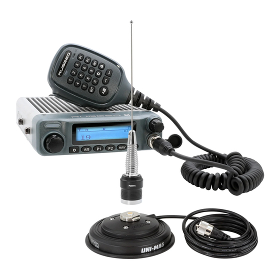
PACKAGE INCLUDES • Radio unit x 1 • Hand Mic with Scosche® MagicMount Magnetic Mount x 1 • Scosche® Magnetic Hand Mic Hanger x 1 • Mobile mounting bracket x 1 • DC power cable with fuse holder x 1 •... -
Page 7: Main Features
MAIN FEATURES Go Further® with our industry leading G1 mobile radio. More wattage equals more power and range, giving you the ability to transmit long-distances when it matters. Easily connect to an intercom with it’s own dedicated port. Use the included Accessory Hub for easy radio programming and external speaker connection! Loaded with channels and features, the G1 is ideal for installation into your vehicle or setup at base camp. -
Page 8: Installation
INSTALLATION MOBILE INSTALLATION Mobile Installation: Select a location that is safe and easy to reach, and protect you and your passengers while the vehicle is in motion. Consider installing the radio in a location and position in which knees and legs will not strike it during sudden braking. Choose a well- ventilated location that is shielded from direct sunlight and heat sources. -
Page 9: Dc Power Cable Connection
INSTALLATION DC POWER CABLE CONNECTION This radio is designed to operate on 12 Volt systems. Never connect to a 24 Volt system without reducing to 12 Volts. If the power supply is lower than 12 Volts, the display may darken during transmissions, transmit power may decrease dramatically, and/or the radio may reboot. -
Page 10: Replacing Fuses
If a fuse blows, determine the cause and correct the problem. After the problem is resolved replace the fuse. If newly installed fuses continue to blow, disconnect the power cable and contact Rugged Radios for assistance. Only use fuses of the specified type and rating otherwise the radio could be damaged. -
Page 11: Accessory Connections
ACCESSORY CONNECTIONS 4-PIN CONNECTOR Connect the Accessory Hub that comes with your radio. Accessory Hub is used for external speaker and easy access for plugging in and programming the radio. EXTERNAL SPEAKERS If you plan to use an external speaker, choose a speaker with an impedance of 8 ohms. The external speaker jack accepts a 3.5mm mono (2-conductor) plug. -
Page 12: Antenna And Cable
ANTENNA AND CABLE Radio performance relies greatly on the antenna and antenna cable! Before operating, install an efficient, well-tuned antenna and a high-quality antenna cable. Failure to do so will reduce transmit and receive range, radio call clarity, and can damage the radio. -
Page 13: Installing The Antenna
- radio range may decrease. For the best range, only the Rugged Radios GMRS POINT5 antenna should be used. Specific installation requirements vary between vehicles. Use the following guidelines to install the antenna. -
Page 14: Getting Acquainted
GETTING ACQUAINTED FRONT PANEL OPERATION Function Quick-Press Long-Press Volume Indicator Illuminates while Light transmitting Volume Knob Turns radio ON/OFF and controls volume 13.8VDC Channel Turn to change Knob channels/ scroll menu EXTSP Enter into Menu/ Use Menu/ DATA as a confirm button Confirm Switch back and forth A/B /... - Page 15 GETTING ACQUAINTED HAND MIC OPERATION FRONT PANEL OPERATION CONTINUED BATT Function Quick-Press Long-Press Quick access to the Preset Ch. 15 Programmable channel you set as P1 Quick access to the Preset Ch. 16 Programmable channel you set as P2 Automatically switch to Go to Ch.
-
Page 16: Rear Panel Operation
GETTING ACQUAINTED REAR PANEL OPERATION Port Function Intercom Port to attach cable that connects to the intercom. Speaker/ Port to attach cable for external speaker and Programming programming cable (Accessory Hub). Power Power connector port (connects to the power cable). Antenna Port to attach coax cable from the antenna. -
Page 17: Menu
GETTING ACQUAINTED MENU Menu Item Operation This function is designed to scan for signals on Scan every channel in the scan list. Increases or decreases the display brightness. Dimmer Changes the display color. Display Color Dims the display after so many seconds of Backlight inactivity. - Page 18 GETTING ACQUAINTED MENU CONTINUED Menu Item Operation Prevents hearing radio traffic on the same Tone Codes frequency. The level of power output used during Tx Power transmission. Wide - Used for shorter distances, with a broader range of frequency communication. Bandwidth Narrow - Used for long-range communication with a comparatively smaller range of frequency...
-
Page 19: Advanced Menu
GETTING ACQUAINTED ADVANCED MENU Menu Item Operation Increases or decreases the volume threshold in which your voice automatically activates a radio transmission. VOX Level Adjusting this level will make it easier or harder to trigger a VOX transmission. Displays firmware version and the date it was Radio Info updated. -
Page 20: Terminology
GETTING ACQUAINTED ADVANCED MENU CONTINUED Turns BT On/Off BT Pairing - Connect headsets or BT speakers Paired Names - Shows BT devices that are connected BT PTT Pair - Connect a BT PTT button Bluetooth BT Hold Time - BT power-saving mode. Increase/ decrease how long the hold time is. -
Page 21: Troubleshooting
TROUBLESHOOTING Problem Possible Cause and Potential Solutions + and - polarities of power connection are reversed. (a) Power is on, nothing appears Connect red lead to plus terminal and black lead to on Display. minus terminal of DC power supply. Check and solve problem resulting in blown fuse (b) Fuse is blown. -
Page 22: Tone Codes
TONE CODES CHANGING TONE CODES Press [ ] to get into menu. Use the [Channel Knob] to navigate to “Tone Codes”, then press [ ] to select it. From within the “Tone Codes” menu, select your desired tone type: “Cross Tone”, “CTC RX”, “CTC TX”, “DCS RX”, “DCS TX”. -
Page 23: Ctcss
GMRS TONE CODES CTCSS Analog Tone Codes This is the Freq. Freq. (Hz) (Hz) number you toggle to on 67.0 167.9 71.9 173.8 your r adio! 74.4 179.9 77.0 186.2 79.7 192.8 82.5 203.5 85.4 210.7 88.5 218.1 91.5 225.7 94.8 233.6 97.4... -
Page 24: Dcs
GMRS TONE CODES DCS Digital Tone Codes DCS (Digital) DCS (Digital) DCS (Digital) DCS (Digital) Code Code Code Code Codes 84-104 may not be supported by other br and GMRS r adios To toggle between numbered tone codes [EX: 22] and actual tone codes [EX:141.3], press [ ] when in tone code menu Only radios produced after March 1, 2022 (signified by a waterproof power connector) are equipped with this feature. -
Page 27: Specifications
SPECIFICATIONS GENERAL Frequency Range TX-462-467MHz RX: 400-480MHz Channel Capacity Frequency Stability ±2ppm Working Temperature -30°C ~ +60°C Working Voltage 13.8V DC Dimension(HxWxD) 53*138*153mm Weight 2.55 lbs. -
Page 28: Receiver
SPECIFICATIONS RECEIVER Receiving Sensitivity 0.25 V @ 12dB SINAD Adjacent Channel Selectivity ≤-60dB@12.5KHz Inter-modulation ≥60dB Spurious Rejection ≥70dB Audio response +1~-3dB Audio Distortion <5% Audio power ≤3W Hum/Noise ≥40dB@25KHz /≥35dB @12.5KHz Standby current 0.16A RX current 0.4A... -
Page 29: Transmitter
SPECIFICATIONS TRANSMITTER Output Power High:40W Middle:25W Low:5W TX Current ≤9A 11K0F3E @ 12.5KHz 14K0F3E @ 20KHz FM Modulation 16K0F3E @ 25KHz Modulation Distortion <5% Hum/Noise ≥40dB@25KHz /≥35dB@12.5KHz Adjacent Channel Power ≤-60dB@12.5KHz Audio Response +1~-3dB Spurious ≤-30dBm12.5kHZ data and audio:7K60FXE... -
Page 30: Notes
NOTES... - Page 31 WWW.RUGGEDRADIOS.COM...
Need help?
Do you have a question about the ADVENTURE Series and is the answer not in the manual?
Questions and answers