Table of Contents
Advertisement
Quick Links
Advertisement
Table of Contents

Related Manuals for Rugged Radios RM50-U/V


Summary of Contents for Rugged Radios RM50-U/V
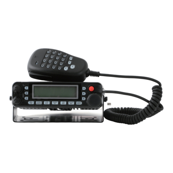
- Page 1 RM50-U/V Dual Band Mobile Radio...
-
Page 2: Thank You
Thank you! Thank you for choosing this transceiver! You’ll feel the performance of this transceiver during using it.enjoy the fun. We suggest you to read the manual carefully before installing this transceiver,for better understanding the functions and the performance of this transceiver. We believe this product can meet your need in voice and data communications,and pro- vide relevant technical support. -
Page 3: Table Of Contents
CCESSORIES Contents UPPLIED CCESSORIES Accessories ............1 Memory Recall ...........29 Microphone MH-RM50 .......................1 Supplied Accessories ........1 Memory Offset Tuning.......29 Mobile Mounting Bracket MMB-RM50 ................1 Installation ............2 Deleting Memories ........30 Installation Tips ..........2 HOME Channel Memory ......30 DC Power Cord w/Fuse (T9021715) ..................1 Safety Information ...........3 Memory Bank Operation ......32 Spare Fuse 15 A (Q0000081) ....................2... -
Page 4: Installation
NSTALLATION NSTALLATION This chapter describes the installation procedure for integrating this radio into a typical AFETY NFORMATION amateur radio station. It is presumed that you possess technical knowledge and conceptu- This transceiver is an electrical apparatus, as well as a generator of RF (Radio Frequency) al understanding consistent with your status as a licensed radio amateur. -
Page 5: Mobile Installation
NSTALLATION NSTALLATION Mobile Power Connections OBILE NSTALLATION To minimize voltage drop and avoid blowing the vehicle’s fuses, connect the supplied DC This transceiver must only be installed in vehicles having a 13.8 Volt negative ground power cable directly to the battery terminals. Do not attempt to defeat or bypass the DC electrical system. -
Page 6: Base Station Installation
NSTALLATION NSTALLATION TATION NSTALLATION TATION NSTALLATION The transceiver is ideal for base station use as well as in mobile installations. The trans- Note that 9600 bps packet transmit-deviation adjustment is very critical to successful opera- ceiver is specifically designed to integrate into your station easily, using the information tion, and can only be accomplished using a calibrated deviation meter (such as that found on to follow as a reference. -
Page 7: Front Panel Controls & Switches
& S & S RONT ANEL ONTROLS WITCHES RONT ANEL ONTROLS WITCHES y [LOW(ACC)] Key Press this key momentarily to select the transmitter power output level (“LOW”, “MID2”, “MID1”, or “HIGH”). Press and hold in this key for 1/2 second to recall the Weather Broadcast Channels. You can program the alternate (press and hold in) function of this key to another function, if desired. -
Page 8: Side Panel Connection & Knob
& K ANEL ONNECTION ANEL ONNECTION : PTT q MIC Jack (Right Side) : MIC : GND q ANT Jack Connect the supplied microphone to this jack. : +9V : SW 1(Key Control) : SW 2 (Key Contol) Connect your antenna here, using a type-M plug (for USA version) or type-N plug (for w Front Panel Release Knob (Left Side) EXP version) and coaxial cable. -
Page 9: Microphone
ICROPHONE ICROPHONE q PTT Switch Press and hold in this key for 1/2 second to enter the Set (“Menu”) mode. Press this switch to transmit, and release [P2] button: it to receive. This button replicates the functions of the front panel [V/M(MW)] key. Press this button momentarily to switch the frequency control among the VFO, w Keypad Memory System, and Home channel. -
Page 10: Basic Operation
ASIC PERATION ASIC PERATION URNING THE RANSCEIVER N AND REQUENCY AVAGATION 1) Tuning Dial 1. To turn the transceiver on, press and hold in the PWR ( ) switch for 1/2 second. Rotating the DIAL knob allows tuning in the pre-programmed steps established for the When you turn on the transceiver, the current DC VFO frequency. -
Page 11: Transmission
ASIC PERATION DVANCED PERATION RANSMISSION EATURE To transmit, simply close the PTT (Push To Talk) In order to prevent accidental frequency change or inadvertent transmission, the trans- switch on the microphone when the frequency is clear. ceiver panel switches, microphone switches (except the PTT switch), and DIAL knob Hold the microphone approximately 25 mm (1”) from may be locked out. -
Page 12: Advanced Operation
DVANCED PERATION DVANCED PERATION ISPLAY RIGHTNESS HANNEL ELECTION The transceiver display illumination has been specially engineered to provide high visibil- The transceiver’s synthesizer provides the option of utilizing channel steps of 5/10/12.5/ ity with minimal disruption of your “night vision” while you are driving. The brightness 15/20/25/50/100 kHz per step, as well as an automatic step selection based on the current of the display is manually adjustable, using the following procedure: operating frequency (“AUTO”), any number of which may be important to your operating... -
Page 13: Repeater Operation
EPEATER PERATION EPEATER PERATION Repeater stations, usually located on mountaintops or other high locations, provide a dra- ANUAL EPEATER HIFT CTIVATION matic extension of the communication range for low-powered hand-held or mobile trans- If the ARS feature has been disabled, or if you need to set a repeater shift direction other ceivers. -
Page 14: Ctcss/Dcs Operation
CTCSS/DCS O CTCSS/DCS O PERATION PERATION CTCSS O CTCSS O PERATION PERATION Many repeater systems require that a very-low-frequency audio tone be superimposed the [BAND(SET)] key momentarily to save the new on your FM carrier in order to activate the repeater. This helps prevent false activation of setting, then press and hold in the [BAND(SET)] key the repeater by radar or spurious signals from other transmitters. -
Page 15: Tone Search Scanning
CTCSS/DCS O CTCSS/DCS O PERATION PERATION EARCH CANNING PLIT PERATION In operating situations where you don’t know the CTCSS or DCS tone being used by an- The transceiver can be operated in a Split Tone configuration via the Set mode. other station or stations, you can command the radio to listen to the incoming signal and 1. -
Page 16: Memory Operation
EMORY PERATION EMORY PERATION The transceiver provides a wide variety of memory system resources. These include: EGULAR EMORY HANNEL PERATION ˆ “Regular” Memory Channels, which includes: Memory Storage € 1000 “Standard” memory channels, numbered “ 000 ” through “ 999 .” 1. -
Page 17: Storing Independent Transmit Frequencies ("Odd Splits")
EMORY PERATION EMORY PERATION EGULAR EMORY HANNEL PERATION EGULAR EMORY HANNEL PERATION Storing Independent Transmit Frequencies (“Odd Splits”) Memory Recall 1. Store the receiving frequency using the method already described. 1. While operating in the VFO mode, press the [V/ 2. -
Page 18: Deleting Memories
EMORY PERATION EMORY PERATION EGULAR EMORY HANNEL PERATION EGULAR EMORY HANNEL PERATION Deleting Memories wish to store, the press the [BAND(SET)] key mo- mentarily to move on to the next character. Letters, With 1000 “Regular” memories available (except memory channel “ 1 ”), there frequently numbers, and symbols are available for storage. -
Page 19: Memory Bank Operation
EMORY PERATION EMORY PERATION EGULAR EMORY HANNEL PERATION EGULAR EMORY HANNEL PERATION Memory Bank Operation Memory Bank Recall Memory Bank Assignment 1. Set the radio to the Memory mode by pressing the [V/M(MW)] key, if necessary. 2. Press and hold in the [SCAN(SEL)] key for 1/2 sec- 1. -
Page 20: Hyper Memory Channel Operation
EMORY PERATION EMORY PERATION YPER EMORY HANNEL PERATION EATHER ROARDCAST HANNEL PERATION The transceiver usually stores, into memory, the operating frequency and some aspects of The VHF Weather Broadcast Station Memory Channel Bank has been pre-programmed at operating status (such as VFO scan, CTCSS/DCS data, repeater shift, power level etc.). the factory, for quick selection of NOAA weather information stations. -
Page 21: Scanning
CANNING CANNING The transceiver allows you to scan just the memory channels, the entire operating band, CANNING or a portion of that band. It will halt on signals encountered, so you can talk to the sta- This mode allows you to scan the entire current operating band. tion(s) on that frequency, if you like. -
Page 22: Memory Scanning
CANNING CANNING EMORY CANNING EMORY CANNING Preferential Memory Scan Memory scanning is similarly easy to initiate: 1. Set the radio to the Memory mode by pressing the [V/M(MW)] key, if necessary. The transceiver also allows you to set up a “Preferential Scan List” of channels which you 2. -
Page 23: Memory Bank Scan
CANNING CANNING (PMS) EMORY CANNING ROGRAMMABLE IMIT EMORY Memory Bank Scan This feature allows you to set sub-band limits for either scanning or manual VFO opera- tion. For example, you might with to set up a limit (in North America) of 144.300 MHz to When the Memory Bank feature is engaged, the scanner sweeps only memory channels in 148.000 MHz so as to prevent encroachment into the SSB/CW “Weak Signal”... -
Page 24: Priority Channel" Scanning (Dual Watch)
CANNING CANNING “P ” S “P ” S RIORITY HANNEL CANNING ATCH RIORITY HANNEL CANNING ATCH WX Priority The transceiver’s scanning features include a two-channel scanning capability which al- lows you to operate on a VFO, Memory channel, Home channel, or Weather Broadcast 1. -
Page 25: Smart Search
MART EARCH MART EARCH The Smart Search feature allows you to load frequencies automatically according to Activating the Smart Search where activity is encountered by your radio. When Smart Search is engaged, the trans- 1. Set the radio to the VFO mode by pressing the [V/M(MW)] key, if necessary. ceiver will search above and below your current frequency, storing active frequencies as 2. -
Page 26: Auto Range Transponder System (Arts)
(ARTS) (ARTS) ANGE RANSPONDER YSTEM ANGE RANSPONDER YSTEM The ARTS feature uses DCS signaling to inform both parties when you and another ARTS ARTS Polling Time Options equipped station are within communications range. This may be particularly useful during The ARTS feature may be programmed to poll every 25 seconds (default value) or 15 Search-and Rescue situations, where is important to stay in contact with other members seconds. -
Page 27: Cw Identifier Setup
(ARTS) ANGE RANSPONDER YSTEM CW Identifier Setup The ARTS feature includes a CW identifier, as discussed previously. Every ten minutes during ARTS operation, the radio can be instructed to send “DE (your callsign) K” if this feature is enabled. The callsign field may contain up to 6 characters. Here’s how to program the CW Identifier: 1. -
Page 28: Dtmf Autodialer Operation
DTMF A DTMF A UTODIALER PERATION UTODIALER PERATION To transmit the memorized telephone number, use the following procedure: Sixteen DTMF Autodialer memories are available on the transceiver. These DTMF Auto- dialer memories can store up to 16 digits of a telephone number for repeater autopatch or 1. -
Page 29: Internet Connection Feature
NTERNET ONNECTION EATURE NTERNET ONNECTION EATURE The transceiver can be used to access a repeater or base station which is configured to the [BAND(SET)] key for 1/2 second to exit to normal operation. provide access to the Vertex Standard WiRES™ (Wide-Coverage Internet Repeater En- 4. -
Page 30: Miscellaneous Settings
ISCELLANEOUS ETTINGS ISCELLANEOUS ETTINGS When APO is activated, the “ ” icon will appear on the LCD. If there is no action by IME-OUT IMER you within the time interval programmed, the “ ” icon The “Time-Out Timer” (TOT) feature is designed to force the transceiver into the “receive” blinks and a ringer sounds 3 minutes before the APO mode after a preset time period of continuous transmission (the default is 6 minutes). -
Page 31: Programming The Key Assignments
ISCELLANEOUS ETTINGS ISCELLANEOUS ETTINGS ROGRAMMING THE SSIGNMENTS ROGRAMMING THE SSIGNMENTS Default transceiver functions have been assigned to “alternate” (press and hold in) func- For Menu #27 PRG PNL tion of the front panel’s [LOW(ACC)] key, as well as the Microphone’s [P1]/[P2]/[P3]/ Press and hold the [ LOW ( ACC )] key Function [P4] buttons’... -
Page 32: Dcs Code Inversion
ISCELLANEOUS ETTINGS ESET ROCEDURE DCS C In the event of erratic operation of the transceiver, it is possible that data on the micropro- NVERSION cessor may have become corrupted. While this is a highly unusual situation, the only path The DCS system was first introduced in the commercial LMR (Land Mobile Radio) ro recovery may involve resetting of the microprocessor. -
Page 33: Cloning
(“S ”) M LONING You can transfer all data stored in one transceiver to another transceiver by utilizing the The transceiver Set (Menu) mode, already described in parts of many previous chapters, handy “Cloning” feature. This requires a user-constructed Cloning cable which connects is easy to activate and set. - Page 34 (“S ”) M “A ” M RESENT PERATING ARAMETERS Item Available Values FREQUENCY RANGE(MHz) MODE STEP Menu Item Function ( Default: Bold Itaric ) Selects the Automatic Power Off time (time before power goes off). OFF/0.5 H ~ 12.0 H 108.000-137.000 25 KHz AR BEP...
-
Page 35: Specifications
PECIFICATIONS ROUBLE HOOTING The problems described in the following tables are commonly encountered operational GENERAL SPECIFICATION malfunctions. These types of difficulties are usually caused by improper hook-up, acci- 108.000-520.000 MHz dental incorrect control settings, or operator error due to incomplete programming. These 700.000-999.990 MHz Frequency Range problems are usually not caused by circuit failure.
Need help?
Do you have a question about the RM50-U/V and is the answer not in the manual?
Questions and answers