Rugged Radios GMR25 User Manual
Hide thumbs
Also See for GMR25:
- Manual (32 pages) ,
- User manual (2 pages) ,
- Installation instructions manual (8 pages)
Table of Contents
Advertisement
Advertisement
Table of Contents

Related Manuals for Rugged Radios GMR25


Summary of Contents for Rugged Radios GMR25
- Page 1 GMR25 USER MANUAL...
- Page 2 1-7, 15-22 or RP15-22, and RUGGED which comprise the GMRS channels of the GMR25. Serious penalties may result from unlicensed use of GMRS channels, in violation of FCC rules, as stipulated in the Communications Act’s Sections 501 and 502 (amended).
-
Page 3: Table Of Contents
CONTENTS User Safety Information Menu Package Includes Menu Options Main Features Squelch (SQL) Initial Installation Back Light Mobile Installation Scan Skip DC Power Cable Connection Sub Screen Fixed Station Operation Radio Info Troubleshooting Replacing Fuses Antenna Connection Specifications Installing the Antenna General Accessories Connections Receiver... -
Page 4: User Safety Information
USER SAFETY INFORMATION • Do not attempt to configure your radio while driving. • This radio is designed for a 13.8V DC power supply. Do not use a 24V battery to power on the radio. • Please keep it away from interference devices (Such as TVs, generators, etc.) •... -
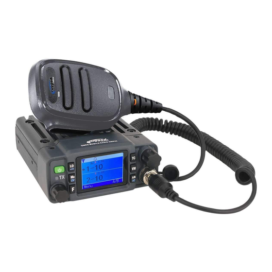
Page 5: Package Includes
PACKAGE INCLUDES • Radio unit x 1 • Hand Mic x 1 • Mobile mounting bracket x 1 • DC power cable with fuse holder x 1 • Screw packs x 1 • Protection fuses x 1... -
Page 6: Main Features
Rugged Radios Accessory Port allowing you to upgrade the radio to do even more! Upgrades include things like: External Speaker, Headsets, intercom systems and more! Whether you are in a 4X4, UTV or other vehicle, the GMR25 is a great option! FEATURES: SPECIAL FEATURES: •... -
Page 7: Initial Installation
INITIAL INSTALLATION MOBILE INSTALLATION Mobile Installation: To install the radio select a safe and convenient location inside your vehicle that minimizes danger to your passengers and yourself while the vehicle is in motion. Consider installing the unit at an appropriate position so that knees or legs will not strike it during sudden braking of your vehicle. - Page 8 INITIAL INSTALLATION MOBILE INSTALLATION (CONT.) Position the radio, then insert and tighten the supplied hex/Phillips screws. Determine the appropriate angle of the radio using the 3 screw hole positions on the side of the mounting bracket. • Double check that all screws are tightened to prevent vehicle vibration from loosening the bracket or radio. •...
-
Page 9: Dc Power Cable Connection
INITIAL INSTALLATION DC POWER CABLE CONNECTION The vehicle battery must have a nominal rating of 12V. Never connect the radio to a 24V battery. Be sure to use a 12V vehicle battery that has sufficient current capacity. If the current to the radio is insufficient the display may darken during transmission or transmitting output power may drop dramatically. - Page 10 INITIAL INSTALLATION DC POWER CABLE CONNECTION (CONT.) Connect the DC power cable to the radio’s power supply connector. Press the connectors firmly together until the locking tab clicks. DC POWER CABLE EXT. POWER JACK...
-
Page 11: Fixed Station Operation
INITIAL INSTALLATION FIXED STATION OPERATION In order to use this radio for fixed station operation you will need a separate 13.8V DC power supply (not included). The recommended current capacity of your power supply is 12A. Connect the DC power cable to the regulated DC power supply and ensure that the polarities are correct. - Page 12 INITIAL INSTALLATION FIXED STATION OPERATION (CONT.) Press the connectors firmly together until the locking tab clicks. Note: Before connecting the DC power to the radio be sure to switch the radio and the DC power supply OFF. Do not plug the DC power supply into an AC outlet until you make all connections.
-
Page 13: Replacing Fuses
If the fuse blows, determine the cause then correct the problem. After the problem is resolved replace the fuse. If newly installed fuses continue to blow, disconnect the power cable and contact Rugged Radios for assistance. Only use fuses of the specified type and rating otherwise the radio could be damaged. -
Page 14: Antenna Connection
ANTENNA CONNECTION Before operating, install an efficient well-tuned antenna. The success of your installation will depend largely on the type of antenna and its correct installation. The radio can give excellent results if the antenna system and its installation are given careful attention. Use a 50Ω... -
Page 15: Installing The Antenna
INSTALLING THE ANTENNA For the best range, only the Rugged Radios GMRS POINT5 antenna should be used. Specific installation requirements vary between vehicles. Use the following guidelines to install the antenna. Where you locate your antenna does make a difference! Avoid metal surfaces covered by fiberglass or vinyl that may affect radio range. -
Page 16: Accessories Connections
ACCESSORY CONNECTIONS EXTERNAL SPEAKERS If you plan to use an external speaker, choose a speaker with an impedance of 8Ω. The external speaker jack accepts a 3.5mm mono (2-conductor) plug. When an external speaker is connected, the radios internal speaker is automatically disabled. -
Page 17: Microphone
ACCESSORY CONNECTIONS MICROPHONE For voice communications, connect the handmic supplied into the modular socket on the front of the panel and tighten the connector nut. Attach the supplied microphone hanger in an appropriate location using the screws includes included in the screw set. Note: Disconnect the hand mic if you are using a microphone equipped accessory connected to the 5-pic cable at rear of the radio. -
Page 18: Getting Acquainted
GETTING ACQUAINTED FRONT PANEL OPERATION TRANSMIT POWER TONE CODE VOLUME INDICATOR BUTTON LOCK MODE KNOB CHANNEL SETTINGS MONITOR SCAN MIC PORT MODE CHANNEL SELECT... -
Page 19: Front Panel Icons
GETTING ACQUAINTED FRONT PANEL ICONS Function Power Press and hold button for 1 second to turn on or off. Volume Knob Turn clockwise/counterclockwise to raise/lower volume Channel Knob Change frequency, memory channel and scan direction, etc Gear Push and hold to access the Function settings Lock Push and hold to lock/unlock the radio Hold to temporarily change the squelch to zero allowing you to... -
Page 20: Display
GETTING ACQUAINTED DISPLAY Icon Function Memory Channel Number High Power Output / Middle Power Output/ Low Power Output CTCSS Encode CTCSS Decode DCS Encode and Decode Beep Positive Direction of Offset Negative Direction of Offset Home Screen Position Scan Locked Keypad... -
Page 21: Rear Panel
GETTING ACQUAINTED REAR PANEL OPERATION Port Function Connection for 50Ω antenna DATA PC programming data port for manufacturing only. EXT SP Terminal for optional external speaker 5-PIN ACCESSORY PORT MUST REMAIN CLOSED TO BE WATERPROOF... -
Page 22: Microphone
GETTING ACQUAINTED MICROPHONE Icon Function Press the key to transmit... -
Page 23: Transmitting
TRANSMITTING Feature Icon Function Hold microphone approximately 1 to 2.5 inches from Menu mouth, press key (#1 shown on page 22), and speak into microphone. -
Page 24: Menu
MENU Feature Icon Function To enter the Menu, press and hold [ ] key. Menu To exit, press the [PTT] button... -
Page 25: Menu Options
MENU OPTIONS Feature Function (Increases/decreases the sensitivity of the radio receiver) OFF: Receiver completely open Squelch 1: Receiver at highest sensitivity 9: Receiver at lowest sensitivity Default Squelch setting is 5 (Controls back-lighting of display) ON: Display stays on continuously Back Light 5S: Display stays on for 5 seconds after seconds of last button press 10S: Display stays on for 10 seconds after last button press... -
Page 26: Troubleshooting
TROUBLESHOOTING Problem Possible Cause and Potential Solutions + and - polarities of power connection are reversed. (a) Power is on, nothing appears Connect red lead to plus terminal and black lead to on Display. minus terminal of DC power supply. Check and solve problem resulting in blown fuse (b) Fuse is blown. -
Page 27: Specifications
SPECIFICATIONS GENERAL Frequency GMRS Frequency stability ±1ppm Operating temperature -30°C ~ +60°C Operating voltage 13.8V DC Dimension 107x125x45mm RECEIVER Sensitivity 0.2μV Inter modulation ≥60dB/≥65dB Spurious rejection ≥70dB Audio response +1~-3dB Audio distortion <5% ≥45dB@25KHz FM hum and noise ≥40dB@12.5KHz Rated audio... -
Page 28: Transmitter
SPECIFICATIONS TRANSMITTER High - 25 watts Maximum Output power Medium: 15 watts Low: 5 watts Transmitting current 4A@13.8V Standby current 0.2A@13.8V FM modulation Narrow band: 11K0F3E Modulation distortion <5% ≥45dB@25KHz FM hum and noise ≥40dB@12.5KHz ≥60dB@12.5KHz Adjacent channel power ≥70dB@25KHz Audio response +1~-3dB... -
Page 29: Notes
NOTES... - Page 30 WWW.RUGGEDRADIOS.COM...
Need help?
Do you have a question about the GMR25 and is the answer not in the manual?
Questions and answers