Table of Contents
Advertisement
Advertisement
Table of Contents

Related Manuals for Rugged Radios M1-V


Summary of Contents for Rugged Radios M1-V
- Page 1 CHANNEL 1 VHF M1-V USER MANUAL VERSION 1.0.2...
- Page 2 SAFETY Safety: This radio generates RF electromagnetic energy during transmit mode. This radio is designed for and classified as “Occupational Use Only,” meaning it must be used only during the course of employment by individuals aware of the hazards, and the ways to minimize such hazards. This radio is NOT intended for use by the “General Population”...
- Page 3 To program your radio and to access advanced features, visit rtsystemsinc.com or contact them at 800-921-4834...
-
Page 4: Table Of Contents
CONTENTS User Safety Information Package Includes Main Features Installation Mobile Installation DC Power Cable Connection Replacing Fuses Antenna and Cable Installing the Antenna Getting Acquainted Front Panel Operation Rear Panel Operation Transmitting Menu Messages Expanded Call Log Expanded Settings Expanded Troubleshooting Specifications General... -
Page 5: User Safety Information
USER SAFETY INFORMATION • Do not attempt to configure your radio while driving. • This radio is designed for a 12 Volt DC power supply. Do not use a 24 Volt battery to power this radio. • Keep this radio away from devices that cause interference, such as TV’s, Generators, etc. -
Page 6: Package Includes
PACKAGE INCLUDES • Radio unit x 1 • Hand Mic with Scosche® MagicMount Magnetic Mount x 1 • Scosche® Magnetic Hand Mic Hanger x 1 • Mobile mounting bracket x 1 • DC power cable with fuse holder x 1 •... -
Page 7: Main Features
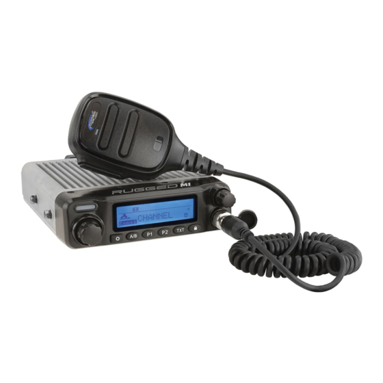
MAIN FEATURES A powerful amplifier, streamlined circuits, and an efficient receiver make the Rugged M1 Mobile 2-way radio go the distance. Designed from the ground up in Arroyo Grande, CA, the Rugged M1 is the culmination of decades of communications accessory manufacturing and first-hand off-road race support from Baja to Crandon, and beyond. -
Page 8: Installation
INSTALLATION MOBILE INSTALLATION Mobile Installation: Select a location that is safe and easy to reach, and protect you and your passengers while the vehicle is in motion. Consider installing the radio in a location and position in which knees and legs will not strike it during sudden braking. Choose a well- ventilated location that is shielded from direct sunlight and heat sources. -
Page 9: Dc Power Cable Connection
INSTALLATION DC POWER CABLE CONNECTION This radio is designed to operate on 12 Volt systems. Never connect to a 24 Volt system without reducing to 12 Volts. If the power supply is lower than 12 Volts, the display may darken during transmissions, transmit power may decrease dramatically, and/or, the radio may reboot. -
Page 10: Replacing Fuses
If a fuse blows, determine the cause and correct the problem. After the problem is resolved replace the fuse. If newly installed fuses continue to blow, disconnect the power cable and contact Rugged Radios for assistance. Only use fuses of the specified type and rating otherwise the radio could be damaged. -
Page 11: Antenna And Cable
ANTENNA AND CABLE Radio performance relies greatly on the antenna and antenna cable! Before operating, install an efficient well-tuned antenna and a high-quality antenna cable. Failure to do so will reduce transmit and receive range, radio call clarity, and can damage the radio. -
Page 12: Installing The Antenna
If your specific vehicle configuration, accessories, or intended use do not allow this, radio range may decrease. For the best range in VHF applications, only the Rugged Radios VHF-1/2W-SPR antenna should be used. Specific installation requirements vary between vehicles. Use the following guidelines to install the antenna. -
Page 13: Getting Acquainted
GETTING ACQUAINTED FRONT PANEL OPERATION CHANNEL 1 VHF Function Indicator Light Illuminates while transmitting. Volume Knob Turns radio ON/OFF and controls volume. Channel Knob Turn to change channels. Function Key Quick-press to enter the menu/confirm. While in dual monitor mode, switches between channel A and B P1/P2 Settings Quick-press P1 for channel 1, quick-press P2 for channel... -
Page 14: Rear Panel Operation
GETTING ACQUAINTED REAR PANEL OPERATION Port Function Intercom Port to attach cable to go to intercom. Speaker/ Port to attach cable for external speaker and program- Programming ming cable. Power Connector to connect to the power cable. Antenna Port to attach coax cable from antenna. -
Page 15: Transmitting
GETTING ACQUAINTED TRANSMITTING Icon Function To transmit, hold microphone approximately 4 inches from mouth, press the key [#1], and speak into microphone. -
Page 16: Menu
GETTING ACQUAINTED MENU Menu Item Operation This function is designed to scan for signals in every channel on the scan list. Press [ ] to open settings menu. Use the Channel Knob to scroll to SCAN and press [ to accept. Press [ ] to select Turn On. - Page 17 GETTING ACQUAINTED MENU Menu Item Operation Press [TXT]. Messages Press [ ] to open settings menu. Use the (Only Shown When Selected Zone is Digital) Channel Knob to scroll to Messages and press ] to accept. Press [ ] to open settings menu. Use the Call Log Channel Knob to scroll to Call Log and press [ (Only Shown When Selected...
-
Page 18: Messages Expanded
GETTING ACQUAINTED MESSAGES EXPANDED Menu Item Function Operation All recieved When in the Messages menu, use the Channel text Knob to scroll to Inbox and press [ ] to accept. messages Inbox will be stored here. When in the Messages menu, use the Channel Choose from preprogramed Knob to scroll to Quick Text and press [... - Page 19 GETTING ACQUAINTED MESSAGES EXPANDED Menu Item Function Operation All sent text When in the Messages menu, use the messages will be Channel Knob to scroll to Sent Items and Sent Items stored here. press [ ] to accept. All text messages When in the Messages menu, use the saved as draft will be Channel Knob to scroll to Sent Items and...
-
Page 20: Call Log Expanded
GETTING ACQUAINTED CALL LOG EXPANDED Menu Item Operation When receiving or transmitting in a digital zone this feature will keep a record of all transmissions from the radio and transmissions received by the radio. You can toggle this feature on and off in Radio Settings. -
Page 21: Settings Expanded
GETTING ACQUAINTED SETTINGS EXPANDED Menu Item Operation When in the Settings menu, use the Channel Knob to scroll to Tones/Alerts and press [ ] to accept. Use the Channel Knob to scroll to All Tones or Talk Permit. All Tones: Enable or disable all radio tones and Tones/Alerts prompts. - Page 22 GETTING ACQUAINTED SETTINGS EXPANDED Menu Item Operation Squelch system allows you to mute the background noise when no signal is being received. Not only is the Squelch system “standby” operation more pleasant, it also significantly reduces battery current consumption. Squelch When in the Settings menu, use the Channel Knob to scroll to Squelch and press [ ] to accept.
- Page 23 GETTING ACQUAINTED SETTINGS EXPANDED Menu Item Operation Toggle the Record feature on or off. When in the Settings menu, use the Channel Knob to scroll to Record and press [ ] to accept. Use Record the Channel Knob to select the desired setting and and press [ ] to accept.
- Page 24 GETTING ACQUAINTED SETTINGS EXPANDED Menu Item Operation Monitor will temporarily change the squelch to zero allowing you to hear very weak signals. When in the Settings menu, use the Channel Knob to Monitor scroll to Monitor and press [ ] to accept. Use the channel knob to select Turn On or Turn Off then press [ ] to accept.
-
Page 25: Troubleshooting
TROUBLESHOOTING Problem Possible Cause and Potential Solutions + and - polarities of power connection are reversed. (a) Power is on, nothing appears Connect red lead to plus terminal and black lead to on Display. minus terminal of DC power supply. Check and solve problem resulting in blown fuse (b) Fuse is blown. -
Page 26: Specifications
SPECIFICATIONS GENERAL Frequency Range VHF: 136-174 MHz Channel Capacity 1000 PLL Channel Spacing 6.25/25/12.5/25KHz Voltage Rating 13.8V DC Operating temperature -30°C ~ +60°C Storage temperature -30°C ~ +85°C Dimensions 143x50x175mm Compatabile with American (MIL-STD-810C/D/E) Military Standard... -
Page 27: Receiver
SPECIFICATIONS RECEIVER Frequency stability (-20C +/-1.0ppm +60C, +25”C) 0.3uV/-117.4dBm(BER 5%) 0.7uV/-110dBm(BER Digital Sensibility 0.35uV/-116dBm(20dB SINAD) Analogue Sensibility 0.22uV/-120dBm(20dB SINAD) Rated audio Adjacent Channel Selectivity TIA603C:60 dB@ 12.5kHz ETSI: 60 dB@ 12.5kHz Intermodulation TIA603C:65 dB ETSI: 65 dB CO-channel Rejection 12 dB@ 12.5kHz Spurious Rejection TIA603C:70 dB ETSI: 70 dB Audio distortion @ rated audio... -
Page 28: Transmitter
SPECIFICATIONS TRANSMITTER FM Hum and Noise -40dB @12.5kHZ Modulation limited +/-2.5kHz @ 12.5kHZ Conducted/radiated -36 dBm < 1 GHz emission -30 dBm >1Ghz < 4GHz -60 dB @12.5kHZ Adjacent channel power -65 dB @ 25kHZ Audio Response +1dB--3dbB Audio distortion FM modulation 12.5kHZ: 11KOF3E 12.5kHZ only data:7K60FXD... -
Page 29: Notes
NOTES... - Page 30 WWW.RUGGEDRADIOS.COM...
Need help?
Do you have a question about the M1-V and is the answer not in the manual?
Questions and answers