Table of Contents
Advertisement
Quick Links
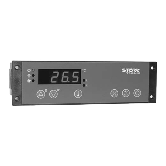
ST181-LM4KAR.112
Controller for cooling applications
Order number 900315.005
Wiring diagram
Product description
The cooling controller ST181-LM4KAR.112 is a control unit specifically designed for 24V DC ven-
tilation adjustment. The maximum ventilation power is 10W. The number of revolutions can be
decreased to 20% and thus create a minimum air speed. Due to the galvanic separation of the
ST181-controller the low-voltage ventilator can also be safely operated in a wet environment.
The two switching outputs for 16A each (engine load max. 1HP) supply the compressor, lighting
or other necessary exits.
Networking of the controller takes place via the ST-Bus interface.
Sensor: PTC
Range: -55...99 C
Front size: 180mm x 52mm
Panel cut-out: 159mm x 45mm
Tightness: Front IP65
Connector: Wieland terminal
Advertisement
Table of Contents

Related Manuals for STORK TRONIC ST181-LM4KAR.112


Summary of Contents for STORK TRONIC ST181-LM4KAR.112
- Page 1 Wiring diagram Product description The cooling controller ST181-LM4KAR.112 is a control unit specifically designed for 24V DC ven- tilation adjustment. The maximum ventilation power is 10W. The number of revolutions can be decreased to 20% and thus create a minimum air speed. Due to the galvanic separation of the ST181-controller the low-voltage ventilator can also be safely operated in a wet environment.
- Page 3 SOFTWARE COOLING CONTROLLER ST181-xxx.112...
-
Page 4: General Information
GENERAL INFORMATION The ST……112 controllers are designed for Key T2: DOWN ( down-arrow ) general use in refrigerating plants. By pressing this key the parameter or parameter value is decreased. A further Depending on the existing hardware, up to four ... -
Page 5: Network Address
In addition to setting the temperature value, the NETWORK ADDRESS buttons DOWN perform other functions, too. Pressing the for 3 seconds will trigger a Under code word you can set a non-standard defrosting operation of the network address. This is required for refrigerating plant. - Page 6 Alarms Buttons and switching inputs Control circuits 1 Defrosting control circuits 1 Fan control circuits 1 Temperature sensors Pre-defined sets of parameters Networking and display Relay contacts and lamps Control circuit 2 These levels by default are protected by a password.
- Page 7 Alarms Para- Description of function Setting range Values meter default Assignment of alarm sensors, detailed 0: none description of sensors in parameters 1: Sensor F1 through 2: Sensor F2 3: Sensor F3 4: Sensor F4 5: weighted mean value from F1 and F2 ...
- Page 8 Buttons and switching inputs (password-protected) Para- Description of function Setting range Values meter default Function button T1 0: without function 1: controller on/standby 2: defrosting request 3: acknowledge alarm 4: relay function light 1, not active in standby 5: relay function light 1 regardless of standby 6: relay function light 2,...
- Page 9 Para- Description of function Setting range Values meter default Function button T6 Function button T7 Function button T8 Function of external switching input E1 0: without function 1: controller on/standby 2: high-pressure alarm (see ...
-
Page 10: Control Circuit
Control circuit 1 Para- Description of function Setting range Values meter default Assignment of cold store sensors, detailed 0: none description of sensors in parameters 1: Sensor F1 through 2: Sensor F2 3: Sensor F3 4: Sensor F4 5: weighted mean value from F1 and F2 ... -
Page 11: Fan Control Circuit
Defrosting control circuit 1 Para- Description of function Setting range Values meter default Assignment of evaporation sensors 0: none (defrosting sensors) 1: Sensor F1 detailed description of sensors in parameters 2: Sensor F2 through 3: Sensor F3 4: Sensor F4 5: weighted mean value from F1 and F2... - Page 12 Para- Description of function Setting range Values meter default Evaporator fan 0: off Fan mode normal operation 1: continuous operation Remark: Control setpoint if >4 2: like 1, with drip interruption 3: with compressor on 4: temperature-controlled evaporator sensor only 5: temperature-controlled difference between cold store and...
-
Page 13: Temperature Sensors
Temperature sensors (password-protected) Para- Description of function Setting range Values meter default Mains frequency 0: 50Hz 1: 60Hz Act. value sensor F1 Measured value, not adjustable Calibration sensor F1 (act. value correction) -20...+20.0°C Weighting factor sensor F1 0.50...1.50 1.00 ... - Page 14 Para- Description of function Setting range Values meter default Display of weighted mean value of F1+F2 + (100- )/100 Weighting of sensor F1 for 0 ... 100% Password of parameter level -99 ...
- Page 15 Relay contacts and lamps (password-protected) Para- Description of function Setting range Values meter default Function relay K1 0: no function (off) 1: compressor 2: defrosting circuit 1 3: evaporator fan 4: condenser fan 5: alarm 6: control contact circuit 2 7: defrosting circuit 2 8: relay function A (light 1) 9: relay function B (light 2)
- Page 16 Para- Description of function Setting range Values meter default Function LED1 0: no function (off) 1: compressor/magnetic valve 2: defrosting control circuit 1 3: evaporator fan 4: condenser fan 5: alarm 6: control circuit 2 7: defrosting circuit 2 8: Light 1 9: Light 2 10: window heating...
-
Page 17: Master Password
Control circuit 2 (password-protected) Para Description of function Setting range Values meter default Assignment of sensors to control circuit 2 0: none detailed description of sensors in parameters 1: Sensor F1 through 2: Sensor F2 3: Sensor F3 4: Sensor F4 5: weighted mean value from... - Page 18 STATUS DISPLAYS AND ERROR MESSAGES Message Cause Remedy Overtemperature, temperature above alarm limit of parameter A1/A31 Undertemperature, temperature below alarm limit of parameter A2/A33 Error on sensor F1, short-circuit check sensor F1 Error on sensor F1, wire broken check sensor F1 ...
- Page 19 Alarm suppression time, door open Alarms With this parameter you can define after which time an alarm is to be triggered when the door is opened. If the door is closed again within the Alarm sensor assignment specified time, no alarm will be triggered.
- Page 20 High-pressure function: Releases until alarm Control circuit 1 In the case of a high-pressure signal via a parameterised switching input, the compressor will Assignment of cold store sensors be switched off immediately and a message will be With this parameter, you can set which sensor input displayed.
- Page 21 Start protection after compressor start "super-frost": lime limit, This protection time starts as soon as the "shock-frost", "max. refrigerating power" compressor is switched on. When the compressor "super-frost": temperature limit, is switched off, it cannot be switched on again until "shock-frost", "max.
- Page 22 Defrosting temperature Password for parameter level A defrosting operation is complete as soon as the With this parameter, you can set the password for temperature set here is reached at the evaporator. parameter level d--. If the defrosting operation is not completed within ...
- Page 23 between the evaporator and the cold store sensor Hysteresis (if =4 or 5) is to be used for controlling the fan. The control The control hysteresis is always set above the setpoint and hysteresis are defined via parameters theoretical switching point.
- Page 24 Condenser fan: Weighting factor F1…F4 Proportional range P-controller With this parameter, it is possible to correct actual For setting of proportional range required if [ value deviations due to unfavourable sensor in which the fan is to be controlled. location.
- Page 25 Display value Pre-defined parameter Here, you can define which actual value is to be sets (password-protected) displayed. This refers to the display in normal operation. You will have to leave the parameter Internal: active data set level in order to see the set value. With this parameter, you can set up pre-defined Possible values which can be set via this data sets.
- Page 26 Relay contacts and Mask on enabled functions (Bit 0...7) lamps (password-protected) Mask on enabled functions (Bit8...15) Here, you can specify the functions enabled via the bus using a binary mask. The bits have the following meaning: Function relay K1...K8 Assignment of internal output signals to the Para Bit Valency Function...
- Page 27 Control circuit 2: upper setpoint limitation Control circuit 2 Control circuit 2: lower setpoint limit (password-protected) With these parameters, you can limit the setting range of setpoint to avoid that the end user Assignment of sensor for independent 2nd does not enter non-permissible values.
- Page 28 Technical data of ST181-LM4KAR.112 Measuring input Temperature sensor PTC Temperature sensor PTC Sensor type: PTC Measuring range -50° C...+130° C Measuring accuracy: ±0.5K ± 0.5 % at 25° C, without sensor ±1K ± 0.5 % of scale range (0...+50° C), without sensor...
Need help?
Do you have a question about the ST181-LM4KAR.112 and is the answer not in the manual?
Questions and answers