Advertisement
Quick Links
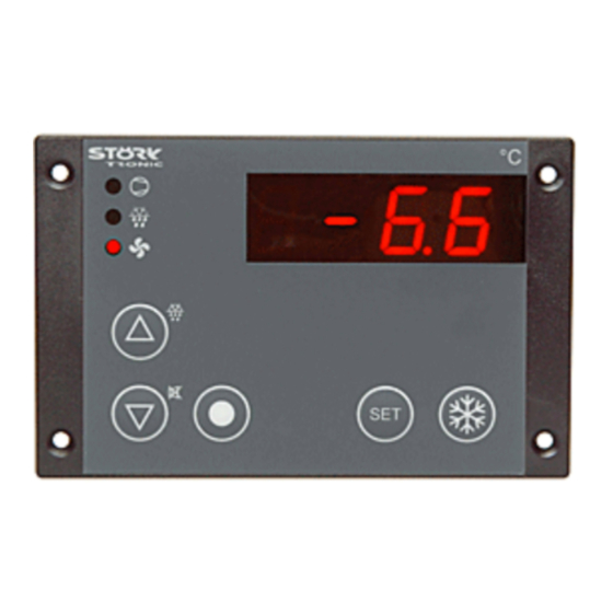
ST501-KU3KA.12P
Controller for cooling applications
Order number 900220.020
As of: 23.03.2015, software V2.24
Wiring diagram
Product description
The microprocessor-controlled controller ST501-KU3KA.12P consists of a service and a separate power
pack plate and is used for thermostatic temperature regulation in simple refrigerating plants. It is supplied
with 230V AC and has four relay outputs as well as an exit for a DC voltage fan.
The relays can be used for different functions, e.g. for a compressor, a defroster, an alarm relay, etc.. (see
parameters U1-U4). The two resistance sensors seize the refrigerating chamber temperature and the
evaporator temperature.
Sensor: PTC
Range: -55...99
C
_
Front size: 106mm x 68mm
Panel cut-out: 87.5mm x 56.5mm
Tightness: front IP65
Connector: cage clamp
Customised Characteristics:
S1=2; P5=0; r1=2; r2=10; c3=2; d0=3; d1=1; d2=5; d3=20; d7=0;
A1=-5; A3=240; A6=0; F5=0; F7=1; F8=71; F9=71; F10=5; b1=4; U3=6;
Order No.: 900220.020
V2.24
1/11
Advertisement

Related Manuals for STORK TRONIC ST501-KU3KA.12P


Summary of Contents for STORK TRONIC ST501-KU3KA.12P
- Page 1 Wiring diagram Product description The microprocessor-controlled controller ST501-KU3KA.12P consists of a service and a separate power pack plate and is used for thermostatic temperature regulation in simple refrigerating plants. It is supplied with 230V AC and has four relay outputs as well as an exit for a DC voltage fan.
- Page 2 Order No.: 900220.020 V2.24 2/11...
- Page 3 SOFTWARE .12 Adjustment options Key 1: UP Defrosting can be started any time by pressing the UP-key for 3 seconds. During the process of defrosting the respective LED is illuminated. The LED flashes if defrosting is requested, but may not be started yet due to interlock conditions. Key 2: DOWN The DOWN key, among other functions, can acknowledge an alarm.
- Page 4 Second control level: Setting of control parameters The parameters can also be set in standby mode. Simultaneously pressing the UP and DOWN key for at least 4 seconds opens a parameter list containing frequently used parameters (the complete list of all parameters is to be found on the third control level).
- Page 5 Para- Function Adjustment range Standard Customer meter setting setting Sensor type Pt100 2-wire (applies to both sensors) PTC 2-wire PT1000 2-wire NTC 2-wire 1: not active Software filter 2...64: average value with 2 ... 64 (applies to both sensors) measuring values Hysteresis for the compressor 1...15 K contact...
- Page 6 Para- Function Adjustment range Standard Customer meter setting setting Function key A 0: no function (if available) 1: controller on/off (standby) 2: Setpoint thermostat 2 (Y1) 3: relay directly, switched off in standby mode 4: relay directly, regardless of standby mode 5: actual value sensor F2 (toggle) Function key B see b1...
- Page 7 Parameter description: The following values can change the equipment characteristics and are therefore to be set with utmost care. P0: Indication actual value of sensor F1 r0: Hysteresis for the compressor contact The here indicated temperature presents the sum of Parameter r0 sets the temperature margin between actual measured value of feeler F1 and the actual switching off and switching on of the compressor.
- Page 8 cooling performance. A1/A2: Minimum/maximum limit values The limit values serve for monitoring of the d0: Defrosting interval refrigerating chamber temperature. They are The defrosting interval defines the time, after which relative, i.e. going along with the setpoint S1 of the a defrosting process is started.
- Page 9 F7: Ventilator function at cooling operation b11: Function external entrance E1 At F7=1 the ventilator is always on (except possibly b12: Function external entrance E2 for a defrosting process, see parameter F4). b13: Function external entrance E3 At F7=2 the ventilator is always on or off together b14: Function external entrance E4 with the compressor.
- Page 10 Status messages Message Cause Error elimination ON/OFF Standby modus, no regulation Switch on by key or switching input Temperature Refrigerating chamber temperature indication flashes beyond alarm limits (parameter A1, A2) Refrigerating chamber sensor F1 error, Control sensor. flashes break or short-circuit Controller operates according to with parameter c3.
- Page 11 Technical data of ST501-KU3KA.12P Measuring input Temperature sensor, refrigerating chamber Temperature sensor, evaporator Measuring range: PTC (KTY81-121) -50°C...+130°C PT1000 -99°C...+300°C -40°C...+105°C Pt100 -80°C...+400°C (resistance < 1 Ohm) Accuracy: ±0.5K ± 0.5 % at 25°C, without sensor ±1K ± 0.5 % of scale range (0 – +55°C), without sensor...
Need help?
Do you have a question about the ST501-KU3KA.12P and is the answer not in the manual?
Questions and answers