Table of Contents
Advertisement
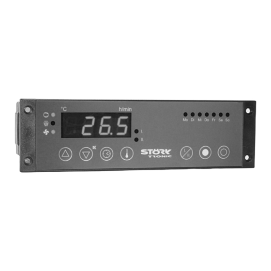
ST181-VL4KA.12
Controller for cooling applications
Order number 900223.015
Old Id.Nr.: 377416
Wiring diagram
Product description
The cooling controller ST181-VL4KA.12 is a control unit specifically designed for 24V DC ven-
tilation adjustment. The maximum ventilation power is 10W. The number of revolutions can be
decreased to 20% and thus create a minimum air speed. Due to the galvanic separation of the
ST181-controller the low-voltage ventilator can also be safely operated in a wet environment.
The three switching outputs with our proven 16A relay allow complete operation of the cooling circle
as well as further additional features, as for example the lighting and many other functions.The
timer allows a 1-week time management for the defrosting periods as well as for setting the cooling
chamber temperature at night or on the weekend. With regard to the parameter level, programming
of this timer is easy and user-friendly. The actual time can be re-set simply directly on the operator
surface.
Sensor: PTC
Range: -55...130 C
Front size: 180mm x 52mm
Panel cut-out: 159mm x 45mm
Advertisement
Table of Contents

Subscribe to Our Youtube Channel
Related Manuals for STORK TRONIC ST181-VL4KA.12


Summary of Contents for STORK TRONIC ST181-VL4KA.12
- Page 1 Wiring diagram Product description The cooling controller ST181-VL4KA.12 is a control unit specifically designed for 24V DC ven- tilation adjustment. The maximum ventilation power is 10W. The number of revolutions can be decreased to 20% and thus create a minimum air speed. Due to the galvanic separation of the ST181-controller the low-voltage ventilator can also be safely operated in a wet environment.
- Page 2 Tightness: front IP65 Connector: Wieland terminal...
- Page 3 SOFTWARE .12 Adjustment options Key UP Defrosting can be started any time by pressing the UP-key for 3 seconds. During the process of defrosting the respective LED is illuminated. The LED flashes if defrosting is requested, but may not be started yet due to interlock conditions. Key DOWN The DOWN key, among other functions, can acknowledge an alarm.
- Page 4 First control level: Parameter setting for the main setpoint. If none of the keys is pressed, the display indicates the actual value of the temperature. Pressing the SET key, the setpoint shows on the display. If the setpoint is to be changed, the SET key is to be kept pressed while adjusting the setpoint with the keys UP and DOWN.
- Page 5 Para- Function Adjustment range Standard Customer meter setting setting Time to switch to data record 0:00...23:59 0:00 2, Monday Time to switch to data record 0:00...23:59 0:00 1, Monday see H11, Tuesday 0:00...23:59 0:00 see H12, Tuesday 0:00...23:59 0:00 see H11, Wednesday 0:00...23:59 0:00 see H12, Wednesday...
- Page 6 Third control level (all parameters): Setting of control parameters Access to the third control level is granted when selecting parameter PA on the second control level. Parameter PA is to be set at '-19'. Then the key UP and DOWN have to be simultaneously pressed for approx.
- Page 7 Para- Function Adjustment range Standard Customer meter setting setting Start protection after 0...240 min. 3 min. compressor stop Function in the case of error 0: relay off of sensor F1 1: relay on 2: emergency operation Defrosting interval 0 = inactive, no defrosting 1...99 h Defrosting mode 0: electrical...
- Page 8 Para- Function Adjustment range Standard Customer meter setting setting Hysteresis for thermostat 2 0,5...15 K (only available if P4=2) Setpoint limitation (minimum) -50°C...Y4 -50 °C thermostat 2 Setpoint limitation (maximum) Y3...150°C +50 °C thermostat 2 Switch mode thermostat 2 0: heating contact 1: cooling contact Function in case of error of 0: relay off...
- Page 9 Para- Function Adjustment range Standard Customer meter setting setting Exit connection K1 0: no connection 1: connection to compressor 2: connection to defrost 3: connection to ventilator 4: connection to alarm 5: connection to thermostat 2 6: connection to function key 1, E1 or E3 7: connection to function key 2, E2 or E4...
- Page 10 Parameter description: The following values can change the equipment characteristics and are therefore to be set with utmost care. P0: Indication actual value of sensor F1 The here indicated temperature presents the sum of actual measured value of feeler F1 and the actual value correction according to parameter P1.
- Page 11 The weighing is only effective, if the sensor F2 is evaluated as evaporator sensor with parameter P4. For the defrost control the not weighed value of sensor F2 is effective. r0: Hysteresis for the compressor contact Parameter r0 sets the temperature margin between switching off and switching on of the compressor.
- Page 12 d3: Defrosting time limit Here the maximal defrosting time can be adjusted. According to this time frame, defrosting is terminated even if the evaporator is not warm enough to be ice-free. d6: Indication of the refrigerating chamber temperature during defrosting It is to be assumed that the refrigerating chamber temperature slightly rises during the defrosting process.
- Page 13 defrosting process would probably be blown into the refrigerating chamber. The ventilator delay is ineffective if the ventilator is on during defrosting and the drainage time is set to “0”. F7: Ventilator function at cooling operation At F7=1 the ventilator is always on (except for a defrosting process possibly, see parameter F4). At F7=2 the ventilator is always on or off together with the compressor.
- Page 14 Y7: Defrosting interval thermostat 2 The defrosting interval defines the time, after which each defrosting process starts. With the beginning of the defrosting process, the defrosting interval starts anew, which results in the periodic defrosting in firm intervals. Y8: Defrosting time limit thermostat 2 Here the maximal defrosting time can be set.
- Page 15 U1: Exit connection K1 U2: Exit connection K2 U3: Exit connection K3 U4: Exit connection K4 Depending on existing hardware there may not be all output relays. This parameter assigns the respective relay to the internal controller exits, to function key 1 or 2, to one external entrance or the buzzer.
- Page 16 Status messages Message Cause Error elimination ON/OFF Standby modus, no regulation Switch on by key or switching input Temperature Refrigerating chamber temperature indication flashes beyond alarm limits (parameter A1, A2) Refrigerating chamber sensor F1 error, Control sensor. Controller operates flashes break or short-circuit according to with parameter c3.
- Page 17 Technical data of ST181-VL4KA.12 Measuring input Temperature sensor PTC, refrigerating chamber Temperature sensor PTC for defrosting, evaporator surface Measuring range: PTC (KTY81-121) -50°C...+130°C Measuring accuracy: ±0,5K ± 0,5 % at 25°C, without sensor ±1K ± 0,5 % of scale range (0 – +55°C), without sensor...
Need help?
Do you have a question about the ST181-VL4KA.12 and is the answer not in the manual?
Questions and answers