Advertisement
Quick Links
ST552 Glass
Deep-frying controller
Order number 900350.011
As of: 14.03.2018, Software V2.70
Wiring diagram
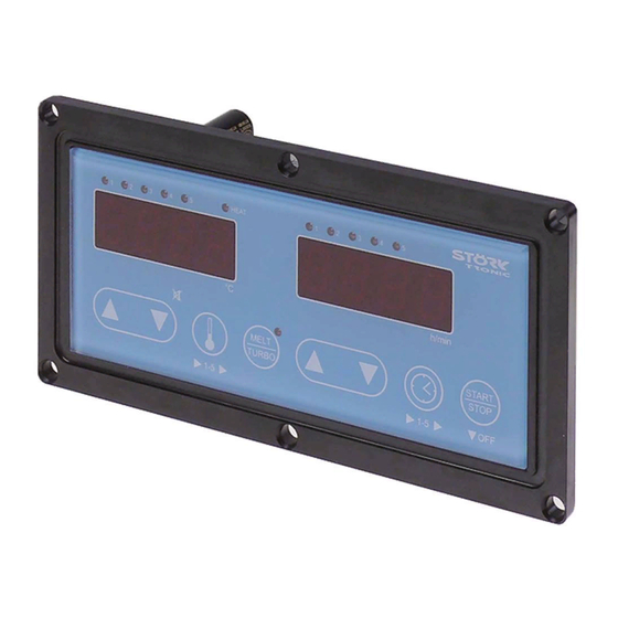
Product description
The deep-frying controller ST552 consists of a touch panel based on a mineral glass. It can easily
be integrated into existing plants and its sturdy surface can replace our approved foil keyboards in
environments with high mechanical or chemical loads. It features two displays, four relay exits and
two digital switching inputs. The two sensor inputs can process a temperature sensor Pt100 or
thermocouple.
Five LEDs arranged above each display indicate the selected temperature and time, respectively.
A delayed key activation and multiple timers are optional.
Via a ST-Bus interface, the controller is connected to networks.
Sensor: Pt100 / Thermo couple Type "J"
Range: -50...700 °C
Tightness: Front IP65
Connector: screw terminals
Order number: 900350.011
V2.70
Seite 1
Advertisement

Related Manuals for STORK TRONIC ST552 Glass


Summary of Contents for STORK TRONIC ST552 Glass
- Page 1 ST552 Glass Deep-frying controller Order number 900350.011 As of: 14.03.2018, Software V2.70 Wiring diagram Product description The deep-frying controller ST552 consists of a touch panel based on a mineral glass. It can easily be integrated into existing plants and its sturdy surface can replace our approved foil keyboards in environments with high mechanical or chemical loads.
- Page 2 Order number: 900350.011 V2.70 Seite 2...
- Page 3 Software deep fryer Displays Display 1: Temperature display LEDs 1...5: Selected temperature Display 1 Display 2 LED Button 4: Turbo heating Display 2: Time display LEDs 1...5: Selected time Design, function and parameterisation The device is designed as a complete built-in unit and for rear installation. The new capacity keypad enables a smooth glass front and makes the device particularly suitable for applications with a high degree of soiling.
- Page 4 Setting options General operating notes: If operated in an environment containing vapour the controller tends to undesired key activations. In this case a delayed key activation can be set with parameter P47. If P47 is set to “1” the keys must be unlocked by a further keypress.
- Page 5 Button 7: Time selection Use this button to select the time to be used by the timer. Scroll to select, each push of the button switches the display further one step. The selected time value remains active even after disconnection of mains supply. Special presets are also possible.
-
Page 6: Parameter Table
Parameter table 1. Setpoint level Parameter Description of function Setting range Default Customer value value Reference temperatures Temperature setpoint 1: P4...P5 110 °C Temperature setpoint 2: P4…P5 120 °C Temperature setpoint 3: P4...P5 130 °C Temperature setpoint 4: P4...P5 140 °C Temperature setpoint 5: P4...P5 150 °C... - Page 7 Para- Description of function Setting range Default Cust. meter value value Button lock Button lock 0: Not locked (Setpoint adjustment disabled) 1: Locked Alarm parameters Lower threshold for alarm -99...999 °C/K -99 K Upper threshold for alarm -99...999 °C/K 200 K Hysteresis alarm, one side 0.1...99.9 K 1.0 K...
- Page 8 Para- Description of function Setting range Default Cust. meter value value Maximum increment / decrement in 1...20 K turbo setup, temperature setting Maximum increment / decrement in 1...20 sec. 5 sec. turbo setup, time setting Key operating mode 0: standard mode (no delay) 1: delayed key operation Key delay for 0.1 ...
- Page 9 Para- Description of function Setting range Default Cust. meter value value Activation of burner clocking 0: Not active 1: Burner clocking below setpoint Duration of basket lowering at K3 at 0...30 sec. 5 sec. start of timer (0 sec. = inactive) Duration of basket raising at K4 at start 0...30 sec.
- Page 10 Para- Description of function Setting range Default Cust. meter value value Timer characteristic Timer function 0: without multiple starts 1: with multiple timer starts Address + version Controller address 1...255 Program version ----- LowFat- and NoContact controll settings General Temperature monitoring a fryer can show whether enough oil is available. The LowFat and NoContact control settings provided by the controller cary out this task.
- Page 11 Fryer design features The special features in the design of the deep-fryer must be taken into account. The temperature measurement value depends on the thermal coupling of the sensor to the oil or heating system. If the thermal coupling disappears with little oil, then the temperature also increases slowly or not at all. Sensor Sensor Electric heating...
- Page 12 Example C: In design C, the sensor is always in thermal contact with the medium. In this case, the lower the amount of oil present, the higher the temperature rise. Example D: Design D has the same characteristics as design A. Parameters involved H1: Temperature rise for sample heating "LowFat".
- Page 13 Selection parameter post-frying time With parameter P77, you can define if the frying time is exactly the programmed time or if the frying time is to be extended if the fried material causes a temperature decrease. Extension of the frying time, also referred to as elastic time or post-frying time, depends on the deviation from the setpoint.
- Page 14 Control function Heating phase without manual intervention Heating phase after significant cooling (refer to Heating phase after activation (refer to Figure 1): After activation and start of the controller, a slow Figure 3): After significant cooling to temperatures below 50 heating phase will always follow when the fat is cold.
- Page 15 Heating phase after significant cooling (refer to Setpoint Figure 3, top): After significant cooling to temperatures below 50 °C, e.g. loading of large quantities of cold fat, a slow heating phase will start, although the change-over to normal heating mode is effected earlier; the heating relay clocks like in the initial heating phase.
- Page 16 Heating with “Superturbo" To obtain always instant heat output in case of need, active “Superturbo” was already deactivated and you can change and activate the switch option to should remain also inactive. You can only switch “Superturbo” with P16. Now the Melt/Turbo button back to slower heating (melt function) below the limit activates the thermostatic control, provided that the from “P73”.
- Page 17 Operation of the timer group Version without multiple start (tic=0): Longer blinking of the timer lamps. Single start It is possible to let the timer lights flash at timer end for up to 3 minutes. This results in a longer signalling After the start of a timer it is not possible to select or start another timer.
-
Page 18: Error And Warning Messages
Error and warning messages Display Cause Remedy Sensor error Check sensor (Heating relay and analogue output are switched off!) Sensor error on compensation element for Repair of controller thermocouple measurement (P91=1,2) Overtemperature at E2 (P35=0, P52=1) ----- Overtemperature at E2 (P35=1, P52=1) ----- Alarm of the LowFat or NoContact control Check oil level and/or switch on/off... - Page 19 Technical data of ST552 Analog inputs Temperature sensor Pt100 or thermocouple TC Measuring range: Pt100 -80...+400 °C -50...+400 °C Measuring accuracy referred to controller at 25 C: +/-0.5 K and +/-0.5 % of measuring range Digital inputs External start-stop button Overtemperature signal contact from temperature limiter Signal outputs Relay, 8(1.5) A / 250 V~, normally-open contact (heating contact)
-
Page 20: Actual Values
Annex ST-Bus A. Actual values (read via ST-Bus-Token ReadRam) Index Name Text Sensor F1: Pt100 Sensor F2: PTC compensation Sensor F3: TC only internal use Setpoint PID: P portion PID: I portion PID: D portion PID: result Relay output Fan output Timer 1 (Start or remaining time) Timer 2 (Start or remaining time) Timer 3 (Start or remaining time) - Page 21 C. Status16 Words (read via ST-Bus-Token ReadRam as actual values) Description Function Message Status 0 (S-0) 0 Controller on if 0: „OFF“ in the display, this bit is writable 10 internal EEProm error „EP“ in the display 12 Check mode on „Pr“...
- Page 22 Status 3 (S-3): internal signals Warning message „Oil“, without blocking Warning message „Oil“,without blocking Warning message „Oil“ acknowledged Acknowledgement for "Oil" enabled (cold fat) Warning „FAt“ LowFat- or NoContact mode is checking LowFat mode active (only once after switching on) NoContact mode active (only once after switching on) Feedback signal given to input E2 (switching direction taken into account) Burner start phase...
- Page 23 LowFat- or NoContact mode is checking LowFat mode active (only once after switching on) NoContact mode active (only once after switching on) Burner feedback at input E2 Burner start phase burner start-up phase Burner restart Burner error Burner is switched on Burner clocking under setpoint value active Burner clocking was active MainFlags[2]...
Need help?
Do you have a question about the ST552 Glass and is the answer not in the manual?
Questions and answers