Table of Contents
Advertisement
Quick Links
ST603-QN1LAR.112
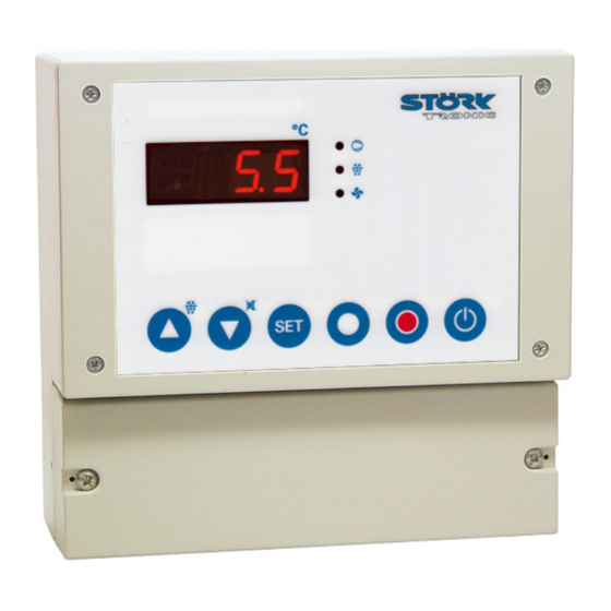
Controller for cooling applications
Order number 900340.012
As of: 26.01.2017, Software V1.54
Wiring diagram
Product description
ATTENTION: Terminal 4-5 (Input E1) is bridged by default!
The cooling controller ST603 with a 3-digit LED display and 6 keys is intended for general operation in refrigerating
plants. The unit is supplied with 230V AC and has three analogue inputs for PTC sensors, four relay exits with high
switching performance and a ST-Bus interface. The controller is installed in a solid plastic housing. The general
functions which can be freely parameterized open the way for a broad application area.
Sensor: 3xPTC
Range: -50...150 °C
Tightness: IP65
Installation size: 166mm x 161mm x 71mm
Connection: high strength cable gland
Order no. 900340.012
V1.54
Page 1
Advertisement
Table of Contents

Subscribe to Our Youtube Channel
Related Manuals for STORK TRONIC ST603-QN1LAR.112


Summary of Contents for STORK TRONIC ST603-QN1LAR.112
- Page 1 ST603-QN1LAR.112 Controller for cooling applications Order number 900340.012 As of: 26.01.2017, Software V1.54 Wiring diagram Product description ATTENTION: Terminal 4-5 (Input E1) is bridged by default! The cooling controller ST603 with a 3-digit LED display and 6 keys is intended for general operation in refrigerating plants.
- Page 2 Order no. 900340.012 V1.54 Page 2...
- Page 3 SOFTWARE COOLING CONTROLLER ST603-xxx.112 Order no. 900340.012 V1.54 Page 3...
-
Page 4: General Information
GENERAL INFORMATION The ST……112 controllers are designed for general Key T2: DOWN ( down-arrow ) use in refrigerating plants. By pressing this key the parameter or parameter value is decreased. A further function of Depending on the existing hardware, up to four ... -
Page 5: Network Address
In addition to setting the temperature value, the NETWORK ADDRESS buttons DOWN perform other functions, too. Pressing the for 3 seconds will trigger a non- Under code word you can set a standard defrosting operation of the refrigerating network address. - Page 6 Alarms Buttons and switching inputs Control circuits 1 Defrosting control circuits 1 Fan control circuits 1 Temperature sensors Pre-defined sets of parameters Networking and display Week timer Relay contacts and lamps ...
- Page 7 Alarms (password-protected) Para- Description of function Setting range Values meter default Assignment of alarm sensors, detailed 0: none description of sensors in parameters 1: Sensor F1 through 2: Sensor F2 3: Sensor F3 4: Sensor F4 5: weighted mean value from F1 and F2 ...
- Page 8 Buttons and switching inputs (password-protected) Para- Description of function Setting range Values meter default Function button T1 0: without function 1:controller on/standby 2:defrosting request 3:acknowledge alarm 4:relay function light 1, not active in standby 5:relay function light 1, regardless of standby 6:relay function light 2, not active in standby 7:relay function light 2, regardless of standby 8:relay function window heating, not active in standby...
-
Page 9: Control Circuit
Para- Description of function Setting range Values meter default Function of external switching 0:without function input E1 1:controller on/standby 2:high-pressure alarm (see 3:low-pressure alarm (see 4:door contact (light on, fan off, see 5:relay function A (light 1), not active in standby 6:relay function A (light 1), regardless of standby 7:relay function B (light 2), not active in standby 8:relay function B (light 2), regardless of standby... - Page 10 Para- Description of function Setting range Values meter default Setpoint for Set1 Night setpoint -20 ... +20.0°C (relative to current setpoint Setpoint for Set2 Switching mode 0: heating 1: refrigerating ...
-
Page 11: Fan Control Circuit
Para- Description of function Setting range Values meter default Temperature difference to cold store setpoint -15°C ... 0.0°C in previous cooling Time limitation in previous cooling 1 ... 180 min. Delay of start of defrosting after compressor 0 ... -
Page 12: Temperature Sensors
Para- Description of function Setting range Values meter default Condenser fan 0: always off function 1: always on 2: on if compressor on 3: after setpoint 4: like 3., as P controller Proportional range P-controller if 0.1 ... - Page 13 Para- Description of function Setting range Values meter default Selection sensor F4 Software filter sensor F4 1 ... 32 Display at 0/4 mA and sensor selection =7/8 -99…+999 Display at 20 mA and sensor selection =7/8 -99…+999 ...
-
Page 14: Week Timer
Week timer (password-protected) Para- Description of function Setting range Values meter default Type (-1: identify automatically) 0: switched off 1: existing Time (European format) 0:00 ... 23:59 Date (European format) 1.1..31.12. Year 2001 ... 2099 ... - Page 15 Relay contacts and lamps (password-protected) Para- Description of function Setting range Values meter default Function relay K1 0: no function (off) 1: compressor 2: defrosting circuit 1 3: evaporator fan 4: condenser fan 5: alarm 6: control contact circuit 2 7: defrosting circuit 2 8: relay function A (light 1) 9: relay function B (light 2)
- Page 16 Para- Description of function Setting range Values meter default Function LED1 0: no function (off) 1: compressor/magnetic valve 2: defrosting control circuit 1 3: evaporator fan 4: condenser fan 5: alarm 6: control circuit 2 7: defrosting circuit 2 8: Light 1 9: Light 2 10: window heating...
- Page 17 Control circuit 2 (password-protected) Para Description of function Setting range Values meter default Assignment of sensors to control circuit 2 0:none detailed description of sensors in parameters 1:Sensor F1 through 2:Sensor F2 3:Sensor F3 4:Sensor F4 5:weighted mean value from F1 and F2 ...
- Page 18 The number of switching cycles is calculated as follows (i.e. for K1): number = 65536 * N1 + N0. Parameter N98 resets the counters for all relays. It depends on the setting of parameter L42. The return value is set back to “0” automatically. T-level (operating times) Parameters are only accessible via ST-Bus.
-
Page 19: Master Password
MASTER PASSWORD All passwords can be edited through Important: Even if you remember the password, you parameterisation. If you don't remember a password, must enter the master password here. If the you can still parameterise the controller and look up password is accepted, you will enter the parameter and/or edit the password via a master password. - Page 20 Behaviour when temperature alarm Alarms disappears Here, you can define if a temperature alarm can be deleted automatically as soon as the temperature is in Alarm sensor assignment the permissible range again or if it must be With this parameter, you can set which sensor input is acknowledged.
- Page 21 after disconnection of the plant from mains supply (and Password for parameter level repair!). With this parameter, you can set the password for parameter level Low-pressure function: Delay until alarm If a low-pressure signal is present via a parameterised ...
- Page 22 Upper setpoint limit "super-frost": deactivation, Lower setpoint limit "shock-frost", "max. cooling power" Setpoints can only be set within the limits If this function is activated, the lower warning limit is defined here. deactivated and the compressor is on permanently. In ...
- Page 23 Defrosting time limitation Fan speed during defrosting, Set2 Here, you can set the max. time in which the defrosting Fan speed during defrosting and active Set1 operation must be completed. After the time set here, the defrosting operation will be Start-up time (in seconds) stopped even if the evaporator was not hot enough to If necessary, the fan can be switched on at max.
- Page 24 Drip interruption time (if Condenser fan: Delay after compressor stop If the fan runs in continuous mode, there is low Off-delay of condenser fan after shut-down of the temperature variation at high atmospheric moisture. In compressor. operation mode "with compressor on", the temperature ...
- Page 25 Weighted mean value sensors F1 and F2 Weighting of sensor F1 for display This theoretical mean value from sensors F1 and F2 (weighted mean value of sensor F1 and F2) may be useful for the control circuit or display. It is This theoretical mean value from sensors F1 and F2 calculated as follows: may be useful for the control circuit or display.
- Page 26 Display value Para Bit Valency Function Here, you can define which actual value is to be Control circuit 1: displayed. This refers to the display in normal Set1 / Set2 change-over operation. You will have to leave the parameter level in Control circuit 1: order to see the set value.
- Page 27 Week timer (password- protected) = 22:30 = 5:00 = 17:30 In the 3 switching operation, the night-time increase is started on Saturday at 17:30 hrs and turned off by Type of internal clock the programming of the 2nd switching operation, i.e.
- Page 28 Password of parameter level Control circuit 2 (password- With this parameter, you can set the password for protected) parameter level Assignment of sensor for independent 2nd control circuit (thermostat) With this parameter, you can set which sensor input is to be assigned to the 2 control circuit.
- Page 29 Technical data of ST603-QN1LAR.112 Measuring inputs Resistance sensor PTC (KTY81-121) Resistance sensor PTC (KTY81-121) Resistance sensor PTC (KTY81-121) (optional linear input, current 4...20 mA) Measuring range: -50°C...+150 °C Measuring accuracy: ±0,5K ± 0,5 % at 25°C, without sensor Outputs Relay, 16(6)A 250V~, normally-open contact...
Need help?
Do you have a question about the ST603-QN1LAR.112 and is the answer not in the manual?
Questions and answers