Advertisement
Quick Links
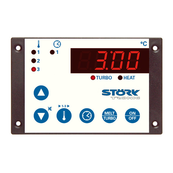
ST501-QE1TA.09
Deep-frying controller
Order number 900219.092
Wiring diagram
Product description
The controller ST501-QE1TA.09 fulfils the function of a temperature controller and is cut to the use
with deep-fryers. It has a 4-digit LED display, 6 keys, 2 relays and a switching input. The different
temperature setpoints and timer defaults can be parametered directly by the keys.
Sensor: multi-resistance input
Range: dependent on the type of sensor
Front size: 106mm x 68mm
Panel cut-out: 87,5mm x 56,5mm
Tightness: front IP64
Connector: screw terminal
Advertisement

Related Manuals for STORK TRONIC ST501-QE1TA.09


Summary of Contents for STORK TRONIC ST501-QE1TA.09
- Page 1 Wiring diagram Product description The controller ST501-QE1TA.09 fulfils the function of a temperature controller and is cut to the use with deep-fryers. It has a 4-digit LED display, 6 keys, 2 relays and a switching input. The different temperature setpoints and timer defaults can be parametered directly by the keys.
- Page 3 SOFTWARE .09 General information The unit is made of a service board and a separate power board which are linked with a ribbon cable. Both parts form a complete installation unit. All outputs and inputs are connected on the back of the power board. The unit fulfils the function of a temperature controller with timer function and is cut to the use with deep-fryers.
- Page 4 Adjustment options Key 1: UP Pressing this key you can increase the parameter or parameter value or scroll the parameter list. Key 2: DOWN Pressing this key you can decrease the parameter or parameter value or scroll the parameter list. At alarm the buzzer function can be switched off with this key. Any fat alarm message can be switched off as well, however the internal alarm condition remains active and the alarm restarts at each unit start.
- Page 5 Key 5+6: Reset operating time recording By a simultaneous pressing of these keys a reset of the time recording is caused, the display indicates “rES”. After releasing the keys the alarm message "OIL" is deleted and if necessary the regulation blocking is cancelled. The accumulated operating time is deleted.
- Page 6 Switching mode of the key MELT/TURBO Status display with LED TURBO flashing = Melt-function off = PID-control on = Turbo-control 1. A6 = 1, A88 = 1 Melt-function and PID-control are activated. The toggle mode of the key depends on the temperature range and if the limit P37 once has been reached.
- Page 7 First control level: Adjustment of the main setpoints and the setpoint reduction The main setpoint is indicated by pressing the UP together with the DOWN key, after a short release time it can be adjusted with these keys. The setpoint reduction is indicated by pressing keys 3+4 together. By additionally pressing the UP or DOWN key it can be adjusted.
- Page 8 Second control level (P-parameters): Adjustment of control parameters The one-finger-setup of the setpoint adjustment requires an exactly simultaneous pressing of the UP and DOWN key for at least 4 seconds to open a parameter list containing control parameters. (If by mistake the setpoint adjustment is released a new attempt is possible after 5 seconds.) With the UP and DOWN keys the list can be scrolled in both directions.
- Page 9 Parameter description: P1: Setpoint / DeltaW for control circuit 2 Adjusting the setpoint of control circuit 2. If A5=1, the setpoints for control circuit 1 and 2 are linked with one another via switching difference DeltaW, which can be adjusted with P1. (operation with DeltaW) The following applies: setpoint thermostat 2 = setpoint control circuit 1 + delta W2.
- Page 10 P9: Lead time Tv (Differential-portion) The differential portion dampens temperature changes. If a long lead time Tv is set, damping is strong. At too long lead time, however, the system may tend to vibrate. At setting 0 the values are ineffective.
- Page 11 P29: Temperature limit for reset of fat operating times To allow a reset of alarm message, regulation blocking and accumulated operating time the fat must be cooled down This paramter determines the temperature value the fat must be cooled down to this value. This is to prevent the user from operating the deep-fryer without replacing the fat.
- Page 12 Third control level, (A parameters): Setting of control parameters Access to the third control level is granted when selecting the last P-parameter on the second control level. Continue to press the UP key for approximately 10 seconds until “PA” appears. Continue to press the UP key and additionally press the DOWN key for about 4 seconds and the first A-parameter of the third control level is indicated.
- Page 13 Para- Function description Adjustment range Standard Custom meter setting setting Special function at 0: no special function boundary alarm 1: flashing display 2: buzzer 3: flashing display and buzzer 4: like 3, buzzer can be cancelled Setpoint display 0: display shows actual value 1: display shows setpoint S1 (S1‘) Switching input E1 (if 0: not active...
- Page 14 Para- Function description Adjustment range Standard Custom meter setting setting Output connection relay K2 0: no connection 1: connection to contact K1 2: connection to contact K2 3: connection to alarm contact 4: on if standby-on 5: on if timer runs Program version ----- -----...
- Page 15 A10: Selection extended frying time With A10=0 the frying time corresponds exactly to the programmed time. With A10=1…20 a weighing factor is specified to compensate a drop of temperature caused by the frying goods. The prolongation of the frying time depends on the deviation of the set point. f( ∆...
- Page 16 A40: Hysteresis mode contact K1 A41: Hysteresis mode contact K2 These parameters allow selection as to whether the hysteresis values which are adjustable with P2, P3 are set symmetrically or one-sided at the respective switching point. At symmetrical hysteresis, half of the hysteresis’ value is effective below and half of the value above the switching point.
- Page 17 A90: Output connection relay K1 A91: Output connection relay K2 Generally, the outputs are exchangeable with parameter adjustments, in order to achieve an optimal relation of the existing hardware with regard to contact rating, kind of contact and number of cycles. Therefore, these parameters first assign the outputs to the controller function. Pro: Program version Indication of the program version.
- Page 18 Technical data of ST501-QE1TA.09 Digital inputs (if available) external potential-free switching contact for timer start The input is intended for a pushbutton. Pressing the button starts the timer. Pressing it again – even if the timer not yet has elapsed – the timer restarts with the selected time.
Need help?
Do you have a question about the ST501-QE1TA.09 and is the answer not in the manual?
Questions and answers