Advertisement
Quick Links
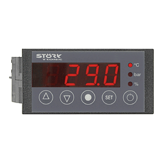
ST710-PWHVR.126
Six-stage controller
Order number 900310.050
Wiring diagram
Product description
The six-stage controller was developed for the control of compressor groups of up to 6 machines,
and/or the control of compressors with bypass-valves (max. 3 machines). The basic gas charac-
teristics are part of the fixed program data - therefore, it is possible to execute a pressure control
(4...20mA) and to show the temperature values at the same time. The compressor running times
can be optimised by help of the sequential or time-conditioned load replacement. The controller
that can be parametered in various ways has an alarm contact and a hour meter.
Networking of the controller takes place via the ST-Bus interface.
Front size: 84mm x 42mm
Panel cut-out: 67.5mm x 31.5mm
Connector: plug and socket
Advertisement

Related Manuals for STORK TRONIC ST710-PWHVR.126


Summary of Contents for STORK TRONIC ST710-PWHVR.126
- Page 1 ST710-PWHVR.126 Six-stage controller Order number 900310.050 Wiring diagram Product description The six-stage controller was developed for the control of compressor groups of up to 6 machines, and/or the control of compressors with bypass-valves (max. 3 machines). The basic gas charac- teristics are part of the fixed program data - therefore, it is possible to execute a pressure control...
- Page 3 SOFTWARE SIX-STAGE CONTROLLER ST710-xxx.126...
-
Page 4: General Information
GENERAL INFORMATION CONTROL KEYS The ST……126 controllers are designed as multi- stage temperature controllers and offer numerous characteristics intended for cooling industries. Depending on the hardware, up to six relay outputs are possible the functions of which can be configured as required via parameters. A special exchange and replacement logic Key T1: UP guarantees a balanced load of the connected... -
Page 5: Network Address
In addition to setting the temperature value, the NETWORK ADDRESS buttons DOWN perform other functions, too. In the case of an alarm (with buzzer triggered), Under code word you can set a DOWN button can be used for acknowledging network address. - Page 6 Plant Buttons and switching inputs Control circuit Sensors Pre-defined sets of parameters Networking and display Main setpoints These levels by default are protected by a password.
- Page 7 Plant Para- Description of function Setting range Values meter default Function of relay K1 in case of sensor error 0: relay off 1: relay on Function of relay K2 in case of sensor error 0: relay off 1: relay on ...
- Page 8 Para- Description of function Setting range Values meter default Alarm suppression after "Power-On" or 0...999 min. after a setpoint/alarm limits change Operating time before time depending load 0...999 (sec. or Min.) replacement Time scale for parameter A33 0: sec.
- Page 9 Buttons and switching inputs (password-protected) Para- Description of function Setting range Values meter default Function of key T1 0: without function 1: controller on/standby 2: Display output power (%) 3: acknowledge alarm 4: Changeover setpoint S1‘ (absolute) 5: Changeover setpoint S1‘‘ (relative) 6: display MIN 7: display MAX 8: display sensor F1...
- Page 10 Control circuit Para- Description of function Setting range Values meter default Auxiliary setpoint S2 absolute (bar or °C) 10.0 DeltaW 1 -99.0 ... +99.9 (bar or °C) 10.0 Auxiliary setpoint S3 absolute (bar or °C) 10.0 ...
-
Page 11: Temperature Sensors
Temperature sensors Para- Description of function Setting range Values meter default Mains frequency 0: 50Hz 1: 60Hz Actual value of sensor F1 Measured value, not adjustable Calibration sensor F1 (act. value correction) -20...+20.0°C Weighting factor sensor F1 0.50...1.50 1.00 ... - Page 12 Networking and display (password-protected) Para- Description of function Setting range Values meter default Own address ST-bus 0: deactivated Identical to setting 1 ... 250 Temperature scale 0: °C 1: °F Display mode 0: 3 digits, integers 1: 3 digits, rounded to 0.5 2: 3 digits, 0.1 3: 4 digits, integers...
-
Page 13: Master Password
MASTER PASSWORD All passwords can be edited through parameteri- Important: Even if you remember the password, sation. If you don't remember a password, you can you must enter the master password here. If the still parameterise the controller and look up and/or password is accepted, you will enter the parameter edit the password via a master password. - Page 14 Additionally, you can define if the buzzer is to Plant sound again after acknowledgement. The corres- ponding time is indicated in A19. The error message and the temperature will be displayed Function of relay K1 in case of sensor error alternately as long as the alarm is present.
- Page 15 Operating time before time depending Operating mode load replacement If a sequential operation mode or the time-depen- dent load replacement is activated with parameter Load replacement depending on time is mainly , parameter selects which used in the field of refrigeration technology to ba- outputs are involved in this mode.
- Page 16 Switch mode relay K1 Switch mode relay K2 Control circuit Switch mode relay K3 Switch mode relay K4 Auxiliary setpoint S2 Switch mode relay K5 Auxiliary setpoint S3 Switch mode relay K6 ...
- Page 17 Hysteresis alarm contact Total operating time K5, hours Hysteresis is set symmetrically at the adjusted limit Total operating time K5, *1000 hours value. It becomes effective depending on alarm The total operating time of the switched-on relay K5 ...
-
Page 18: Sensor Selection
Sensor selection F1 / F2 Pre-defined parameter With this parameter, you can define the sensor sets (password-protected) type. Depending on the hardware, not all sensor types may be supported. For the NTC sensor, a Intern: active data set parallel resistor will have to be connected. - Page 19 Mask on enabled functions Networking and Here, you can specify the functions enabled via the display (password-protected) bus using a binary mask. The bits have the following meaning: ST-Bus own address With the address set here, the controller can be Para Bit Valency Function ...
- Page 20 Appendix A: If one of the parameters , or is changed, the following values are set automatically: If parameter is modified all parameters are reset to their default value, even if they are not listed in the table below. The operating times of the relays and the passwords of the individual parameter levels are excluded from this.
- Page 21 30.0 30.0 30.0 30.0 30.0 30.0 -0.9 -0.9 -0.9 -0.8 -0.9 30.0 30.0 30.0 30.0 30.0 30.0 S1‘ S1‘‘...
- Page 22 Appendix B: Conversion help to convert the former controller ST710-PWHV.26 into the new ST710-PWHVR.126: Description Notice .126 Setpoint S2 Delta W1 Setpoint S3 Delta W2 Setpoint S4 Delta W3 Setpoint S5 Delta W4 Setpoint S6 Delta W5 Hysteresis K1 Hysteresis K2...
- Page 23 Display mode -> L3 Alarm mode Special function -> A18 More selections possible Minimum action time for -> A21 K1 "Off" Minimum action time for -> A22 K2 "Off" Minimum action time for -> A23 K3 "Off" Minimum action time for ->...
- Page 24 Appendix C: Table of actual values of the six-stage controller (Ac25_001) read via ST-Bus by ReadRam and/or ReadRamBurst: burst Description Unit Actual value °C/bar Actual power demand Setpoint °C/bar Actual MIN value °C/bar Actual MAX value °C/bar Actual value °C Actual power demand Setpoint °C...
- Page 25 Status S0 Status S1 Status S2 Status S3 Controller on S1‘ absolute active Input E1 Control circuit 1 active S1‘‘ relative active Input E2 Reset Min Defrosting activated Reset Max Acknowledge alarm Pressure display Battery operation Relay K1 Error EP0 Relay K2 Error EP1 Relay K3...
- Page 26 Technical data of ST710-PWHVR.126 Input External potential-free switching contact Measuring input Resistance thermometer Pt100-3L Measuring range: -200°C...350°C Measuring accuracy: 0.5K +/- 0.5 % of scale range, without sensor Operating range in case of temperature display like measuring range of the sensor, otherwise -0.9...30.0 bar or –65...85 °C with R134A and -80...63 °C with R507.
- Page 27 Connectors Plug and socket Terminal A: 12-pole, spacing 5.0 mm, for cable up to 2.5 mm² Terminal B: 11-pole, spacing 3.5 mm, for cable up to 1.5 mm² Enclosure Front IP65, IP00 from behind Installation data Unit is to be installed in an instrument panel. Front size: 84 x 42 mm Panel cut-out:...
Need help?
Do you have a question about the ST710-PWHVR.126 and is the answer not in the manual?
Questions and answers