XCHARGE C6EU Series Installation And Operation Manual
Hide thumbs
Also See for C6EU Series:
- Preventive maintenance instructions (3 pages) ,
- Installation and operation manual (27 pages)
Table of Contents
Advertisement
Advertisement
Table of Contents

Related Manuals for XCHARGE C6EU Series


Summary of Contents for XCHARGE C6EU Series
- Page 1 C6EU SERIES Installation and Operation Manual ENGLISH...
-
Page 3: Changelog
Copyright XCHARGE reserves all rights to this document and to the information and topics contained in it. This also applies to any possible claims to copyright or patents. Forwarding and/or the duplicating of this document without the express permission of XCHARGE is forbidden. -
Page 4: Table Of Contents
Power supply and power cable ................21 Packaging and Unpacking..................22 4.5.1 Packaging ......................22 4.5.2 Unpacking ......................23 Positioning and wiring .................... 23 Verification of measurement values ............... 26 Copyright | C6EU SERIES Installation and Operation Manual, Version 1.6... - Page 5 Charging process ..................... 28 Indicator lights ......................31 Fault diagnosis ......................31 Maintenance ........................ 34 Cleaning of the cabinet ................... 34 Anti-dust net replacement ..................34 Contact Information ....................36 Copyright | C6EU SERIES Installation and Operation Manual, Version 1.6...
-
Page 6: Introduction And Safety Information
When any loss or damage occurs due to improper use or unauthorized modification of the product, XCHARGE SHALL NOT be liable for the product, the purchaser or third parties. The same is also valid if the maintenance provided by XCHARGE is not strictly complied. -
Page 7: Important Safety Instructions
Do not start and drive your EV when socket is still connected. The user is responsible for the damage to the EV and charging station caused by former addressed case. Copyright | C6EU SERIES Installation and Operation Manual, Version 1.6... -
Page 8: Important Signs
Electricity Hazard Warning of electrical voltage Crushing of Hands Touching the device may result in hand injury No access for people with active implanted cardiac devices Table 1.5.1 Warning Signs Copyright | C6EU SERIES Installation and Operation Manual, Version 1.6... - Page 9 Do not dispose of the product with domestic waste. Please follow the valid disposal regulations in the installation site for electronic waste. CE Mark Table 1.5.2 Other signs on the nameplate Copyright | C6EU SERIES Installation and Operation Manual, Version 1.6...
-
Page 10: Product Description
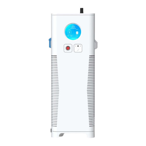
HD/Touch screen, diameter 22.5 cm LED Indicator (HMI) Emergency button Charging connector Control panel with RFID/Credit card Cable management reader system Air inlet Air outlet Table 2.1.1 Housing and exterior elements Copyright | C6EU SERIES Installation and Operation Manual, Version 1.6... - Page 11 SN number, for example in SN number “C6E12JC20IQBHUVPW” the type is C6EU- 120, up to 120kW output with CCS and CHAdeMO connector; • Touch or non-touch screen is optional for all these kinds of C6EU. Figure 2.1 Rendering of C6EU Copyright | C6EU SERIES Installation and Operation Manual, Version 1.6...
-
Page 12: Charging Connector System
2.2 Charging connector system CHAdeMO CCS Combo 2 (CCS2) Table 2.2 Structure sketch of charging connectors: CHAdeMO and CCS 2 Copyright | C6EU SERIES Installation and Operation Manual, Version 1.6... -
Page 13: Technical Data
200 – 1000 V (Combo-2) Output voltage range 200 A or 250 A or 300 A continuously (CCS 2) Maximum output current < 5 % (50-100% of rated output power) Copyright | C6EU SERIES Installation and Operation Manual, Version 1.6... -
Page 14: Mechanical Data
2100 mm x 850 mm x 900 mm Weight including packaging 375 (60 kW) - 450 kg (200 kW) Weight concrete foundation Min. 450 kg Mechanical impact protection IK10 Table 3.3.1 Mechanical data of C6EU Copyright | C6EU SERIES Installation and Operation Manual, Version 1.6... -
Page 15: Environmental Data
EN 301 489-52 V1.1.0 (2016-11) EN 300 330 V2.1.1 (2017-02) EN 301 511 V12.5.1 (2017-03) Radio EN 301 980-1 V11.1.1 (2016-07) EN 301 980-2 V11.1.2 (2017-08) Table 3.5.1 Technical standard of C6EU Copyright | C6EU SERIES Installation and Operation Manual, Version 1.6... -
Page 16: Electrical Diagram
The diagram was already approved by TÜV Rheinland according to Standard EN 61851- 23. For different types of C6EU the size of cable in the electrical connection diagram is variable. Copyright | C6EU SERIES Installation and Operation Manual, Version 1.6... -
Page 17: Function Structure Of C6Eu
3.7 Function Structure of C6EU The Figure 3.7.1 below introduces the structure of C6EU from basic to sophisticated functions. Figure 3.7.1 C6EU function structure Copyright | C6EU SERIES Installation and Operation Manual, Version 1.6... -
Page 18: C6Eu Power Curve
3.8 C6EU Power Curve Type Power Curve (V/I) C6EU 60kW C6EU 120kW Copyright | C6EU SERIES Installation and Operation Manual, Version 1.6... - Page 19 C6EU 150kW C6EU 200kW Table 3.8.1 C6EU power curve Copyright | C6EU SERIES Installation and Operation Manual, Version 1.6...
-
Page 20: Installation
4. Installation The product will be delivered to a warehouse by logistic company and handed over to the customer. Normally XCHARGE is not responsible for the transport of charger to final installation location. 4.1 Required space for placing and maintaining The space that C6EU needs is calculated as follows: Vertical view: 740 mm x 615mm;... -
Page 21: Installation Warnings
Figure 4.3.1 as an example for the C6EU 200kW. If you do not use a Prefabricated foundation, please notice the hardening times of the applied concrete before installation. Figure 4.3.1 Dimension of C6EU 200kW foundation Copyright | C6EU SERIES Installation and Operation Manual, Version 1.6... - Page 22 • The selection of power cable specifications should be selected according to the installation environment and fire requirements. Foundation Ground PVC Pipe Figure 4.3.2 Sketch of the foundation layers Copyright | C6EU SERIES Installation and Operation Manual, Version 1.6...
-
Page 23: Power Supply And Power Cable
M90 (62 - 70 mm) 5 power modules 4P 400A with RCD Type A 1x95 mm Table 4.4.2 Suggestion for the cable dimension of all types C6EU (cable length within 40m) Copyright | C6EU SERIES Installation and Operation Manual, Version 1.6... -
Page 24: Packaging And Unpacking
It is necessary to ensure vertical transportation. If the indicator turns red, it can be considered that during transportation severe impact and tilt occurs. Figure 4.5.1 Tilting detector on the package Copyright | C6EU SERIES Installation and Operation Manual, Version 1.6... -
Page 25: Unpacking
Figure 4.6.1 the width of fork is up to 420mm and the length of fork is min. 600mm. Please move the charging station with the utmost caution! Figure 4.6.1 Forklift parameter Copyright | C6EU SERIES Installation and Operation Manual, Version 1.6... - Page 26 (for example from floor to Foundation). For more than 150kW because of the weight forklift is suggested by XCHARGE to apply. Please ensure that the body of C6EU stays stable during moving through crane or forklift to avoid the possible swinging, which may cause damage to the charger;...
- Page 27 Figure 4.6.4. (it’s suggested to use such soft flat LAN cable like in figure because of the limited place for installation. Any other RJ45 converter in the charger could be installed by customer if needed) Copyright | C6EU SERIES Installation and Operation Manual, Version 1.6...
-
Page 28: Verification Of Measurement Values
Extension cables are not permitted according to IEC 61851-1. If an extension cable or a second cable set is used, there is a risk of electric shock or cable fire. Copyright | C6EU SERIES Installation and Operation Manual, Version 1.6... -
Page 29: Commissioning And Operation
5.2.1 Display and usage This will be the home page shown on screen after the charger is powered up. Touch screen Non-touch screen Figure 5.2.1 Start page for touch and Non-Touch screen Copyright | C6EU SERIES Installation and Operation Manual, Version 1.6... -
Page 30: Control Panel
• Icon: the charging connector sign on screen; • Overtime: There is no action or no proper operation from the user within specified time; • RFID: Radio Frequency Identification card; Copyright | C6EU SERIES Installation and Operation Manual, Version 1.6... - Page 31 1. Select charging icon and wait for the the authentication authentication 2. Authentication passed, waiting for the 2. Authentication passed, waiting for the official charging process official charging process Copyright | C6EU SERIES Installation and Operation Manual, Version 1.6...
- Page 32 4. The bill page after charging 4. The bill page after charging 5. Press “OK” to complete charging session 5. Press home button on control panel to complete charging session Figure 5.3.4 UI screenshot Copyright | C6EU SERIES Installation and Operation Manual, Version 1.6...
-
Page 33: Indicator Lights
Power module 1005 Check the CAN communication EVSE communication failed connection between power module and DCB module Meter for connector 1 Check the connection and 1007 EVSE warning communication of electricity Copyright | C6EU SERIES Installation and Operation Manual, Version 1.6... - Page 34 2016 EVSE failure status 2017 EV battery reverse wiring Check EV EV battery voltage 2018 Check EV abnormal 2019 EV battery overvoltage Check EV 2021 EV battery undervoltage Check EV Copyright | C6EU SERIES Installation and Operation Manual, Version 1.6...
- Page 35 When scanning QR-code or sweeping NFC/RFID card to start charging and system shows self- test failure: due to the difference of EVs inlets, plug the socket again to ensure that the charging connector is in the right position and lock functions well. Copyright | C6EU SERIES Installation and Operation Manual, Version 1.6...
-
Page 36: Maintenance
In order to change the anti-dust net in 10min, quick change method is applied. After opening the front door and lifting the lock bar, the cover will open, then wash, air-dry the net, install the anti- dust net and locks back. Copyright | C6EU SERIES Installation and Operation Manual, Version 1.6... - Page 37 When opening the front and rear doors, please pay attention to prevent dust from entering the cabinet and clean if necessary. Copyright | C6EU SERIES Installation and Operation Manual, Version 1.6...
-
Page 38: Contact Information
Borsteler Bogen 27 B 22453 Hamburg GERMANY Tel: +49-160 6255066 Email: eu@XCHARGE.com Contact for China: Beijing XCHARGE Technology Co., Ltd. 12 Shuangyang Road Daxing District 100176 Beijing CHINA Tel: +86-1057215988 Email: b@XCHARGE.com Copyright | C6EU SERIES Installation and Operation Manual, Version 1.6...
Need help?
Do you have a question about the C6EU Series and is the answer not in the manual?
Questions and answers