Advertisement
Quick Links
V1.1
NZS
Installation and
Operation Manual
Series
Copyright | NZS Installation and Operation Manual
Xcharge reserves all rights to this document and to the information and topics contained in it. This also applies to any possible claims to copyright
or patents. Forwarding and/or the duplicating of this document without the express permission of XCHARGE is forbidden.
Advertisement

Related Manuals for XCHARGE NZS Series


Summary of Contents for XCHARGE NZS Series
- Page 1 Copyright | NZS Installation and Operation Manual Xcharge reserves all rights to this document and to the information and topics contained in it. This also applies to any possible claims to copyright or patents. Forwarding and/or the duplicating of this document without the express permission of XCHARGE is forbidden.
- Page 3 Legal Provisions All the information in this document is the property of XCHARGE Tech Co., Ltd. No part of this document could be reproduced in any way for business use. Internal use is allowed. XCHARGE Tech Co., Ltd. makes no representations or warranties express or implied, con- cerning this document or any of the equipment and/or software it may describe, including (with no limitation) any implied warranties of utility, merchantability, or fitness for any...
-
Page 4: Table Of Contents
Contents /Information and safety....................1 /Product description ....................6 /Package and Transportation..................13 /Installation........................14 /Conmissioning ......................31 /User interface ......................36 /Maintenance ......................44... -
Page 5: Information And Safety
·Contractors who are qualified electricians performing installation, commissioning, maintenance or repair of the XCHARGE NZS Models. ·XCHARGE employees and after-sales service personnel who are responsible for NZS Models. The instructions in this document may only be performed by qualified persons who must have the following skills: ·Knowledge of how batteries work and are operated... - Page 6 In case of loss or damage due to improper use or unauthorized modification of the prod- uct, XCHARGE shall not be liable for the product, the purchaser or any third party. The same also applies if the maintenance provided by XCHARGE is not strictly observed.
- Page 7 3、 Please do not start operation until the system has been fully commissioned and checked by XCHARGE technicians or until all required scheduled maintenance has been carried out. Before installing or cleaning the charging station, disconnect the power supply.
- Page 8 1.4 Signs Signs Description Earthing Connect an earth terminal to earth General Warning Sign Identify a hazard that may result in damage to the operator, machinery, other equipment and / or contamination. Electricity Hazard Warning of electrical voltage Crushing of Hands Touching the device may result in hand injuries No access for people with active implanted cardiac devices...
- Page 9 1.5 Designation in the Document Alternating Current Battery Management System Battery Control Unit Battery Information Collector Battery Management Unit Beginning of Life Balance of Plant Center of Gravity Distribution Management Cabinet Direct Current EMCU Energy Management Control Unit Emergency Response Plan Energy Storage System Factory Acceptance Test Human Machine Interface...
-
Page 10: Product Description
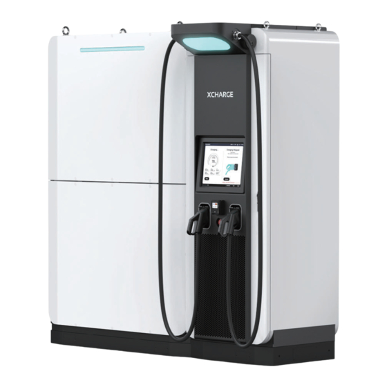
Designed with the essence of XCHARGE, this disruptive technology applies a completely new modular upgrade and intelli- gent software system for the whole E-mobility market. It is a significant proof point to cut carbon emissions in our entire product portfolio and make EV charging green. - Page 11 HVAC system for battery Electricity meter cooling/heating Air outlet for charger unit Industrial socket Mounting position installation area for Nameplate NZS charger can be configured with one or two ESS: Net Zero Series Battery Volume: 233kWh(1 ESS left) or 466kWh(2 ESS one for each side) Copyright | NZS Installation and Operation Manual...
- Page 12 2300 1123 Copyright | NZS Installation and Operation Manual...
- Page 13 It contains type of charger, input/output, battery capacity, manufacture date and address, part number, serial number and safety signs. Importer: XCHARGE Europe GmbH Borsteler Bogen 27B, 22453 Hamburg Type: NZS/233...
- Page 14 Input Voltage 3Phrase 400VAC +/- 15% Circuit breaker Type A Input Frequency 50Hz±1Hz Input & Output Output Voltage Range 150VDC-1000VDC Constant-power voltage output range 300VDC-1000VDC Nominal power output 150kW + 30kW/60kW Current output 250A CCS2 continuously (200A optional) General Parameters Type DC charging station Dimension...
- Page 15 GSM900: 880-915MHz(UL), 925-960MHz(DL) 33.04dBm DCS1800: 1710-1785MHz(UL), 1805-1880MHz(DL) 30.92dBm WCDMA B1: 1920-1980MHz(UL), 2110-2170MHz(DL) 23.5dBm WCDMA B8: 880-915MHz(UL), 925-960MHz(DL) 22.8dBm RF Output Power LTE Band 1: 1920-1980MHz(UL), 2110-2170MHz(DL) 23.6dBm LTE Band 3: 1710-1785MHz(UL), 1805-1880MHz(DL) 23.5dBm LTE Band 7: 2500-2570MHz(UL), 2620-2690MHz(DL) 23.0dBm LTE Band 8: 880-915MHz(UL), 925-960MHz(DL) 23.1dBm LTE Band 20: 832-862MHz(UL), 791-821MHz(DL) 22.0dBm...
- Page 16 Charging Connectors CCS Combo 2 different current varieties are available to choose. There are three kinds of current level to use 200A, 250A and 300A. Of which, 250A and 300A cables can support up to 400Afor certain period based on ambient temperature and connector temperature. For each, cable length is free to be customized from 3m to 10m.
-
Page 17: Package And Transportation
2.3 Applicable scenarios Because of low input requirement, NZS is flexible to be applicated in varies scenarios: Highway refueling stations: Due to remote location, there is only limited power supply condi- tion at refueling stations on highway. NZS only needs max. 70kW for input and output more than 200kW, which realize fast charging demand on highway. -
Page 18: Installation
Package of metal basement is made with full PLYWOOD, showed in following picture. (Package of metal basement) 3.2 Transportation To transport the product in package, forklift must be prepared before transportation. The lashing and securing method is suitable for transportation. For charger unit, at least two binding belts must be through top of charger and fasten the product. - Page 19 The product is delivered to a warehouse by a logistics company and handed over to the customer. Normally, XCHARGE is not responsible for transporting the charger to the final installation site. During Installation there will be XCHARGE Service Colleagues for guidance.
- Page 20 The metal base of this product needs to be fixed to a concrete base, please refer to the diagram below to create the installation base in advance on site. The requirement for this concrete base is as follows: Concrete base height H0≥300mm Load bearing capacity >...
- Page 21 4.2 Unpacking CAUTION Check whether the outer package is complete, there is no breakage, crack, scratch, etc. Considering that the center of gravity of the products is high and to one side, when forklift trucks are handling the products, the fork arms should be spread out as far as possible, the fork arms should be inserted into the pallet as deep as possible in the front and rear directions, and the start/stop and transfer should be carried out slowly.
- Page 22 (1)Release metal buckles of top cover and remove the cover Front (2)Release metal buckles of front cover and remove the front cover Front (3)Release metal buckles for left cover and remove left wooden cover Front (4)Release other buckles with colleague’s help and then remove all wooden covers Copyright | NZS Installation and Operation Manual...
- Page 23 4.3 Installation of Products Metal Base Installation Prepare the impact drill, confirm the drill bit specification M12, check the specification and number of expansion screws. Referring to the following fixed hole position, use the impact drill to align the hole center drilling, drilling depth of 150mm. Put the metal base on concrete base.
- Page 24 NZS offers different kinds of cable connection varieties. One of them is to connect input cables directly to input busbar inside of charger. In this case, cable can go from underground, through concret foundation, to charger inside from its bottom. If this is the choice, cable groove in founda- tion should be cut as showed in the red marked area.
- Page 25 Installation steps: ・Crane specifications: the weight of ESS is 2.6T, the need to use the rated lifting weight ≥ 5T motor crane, sling 4 (equal length), each sling length ≥ 5m. ・Climb up the man-ladder, connect the sling with the 4 rings on the top of ESS, and pull the sling until it is taut, but do not lift the equipment so that the cardboard is off...
- Page 26 Charger Installation There is production tolerance during ESS and charger production. Assembly two part together might result in superimposed tolerance, so that a slant gap will present between ESS and charger. To avoid this, a separate leveling mechanism is designed for charger part. The installation must be metal base first, then ESS, charger at last and leveling adjustment for charger after all installation finished.
- Page 27 4.4 Cable Connection DANGER All cable connection of this product requires a qualified electrician to complete. When connecting or installing the copper row, you must wear insulated gloves to prevent electric shock and confirm that the wiring harness is intact. Please refer to the diagram when connecting the homemade harness, according to the line label positive and negative access.
- Page 28 Grid Connection Power supply requirements: Nominal Nominal Cable Power Diameter Voltage Current dimension 400V P+N+PE, 68kW 5 x 35mm 30 – 35mm 50Hz As mentioned in 4.3.1, NZS provides different alternatives for grid connection. Besides cable going through concret foundation directly up to charger inside, industrial socket can also be chosen to connect charger with grid, as shown in bellowing picture, marked as ①.
- Page 29 To connect like usual, the hole marked with ② on metal base can also be used for input con- nection. Please open rear door and disconnect the cables for industrial socket on left side of charger inside. Input cable go through metal base and enter charger inside through metal cable glands.
- Page 30 Battery Connection Metal base enables cable connection between ESS and charger. A channel in metal base, as shown with a red path, consists of ESS cabinet and charger cabinet without any under- ground grooves. (Front side) (Back side) Interface between ESS and charger are presented in below table: Description Interface type Quantity...
- Page 31 Use an electric screwdriver to remove the screws on the rear lower door panel, then move the door aside and confirm that the switch is disconnected according to the following table power state. Then connect cables referring to electrical diagram. Switch Status Status confirmation...
- Page 32 Windproof pole is designed to avoid deformation or damage of door during severe weather, showed in following picture. Two poles are at lower side of upper door and top side of lower door, which is easy to get and operate. (Windproof pole)...
- Page 33 To ensure insulation safety, there are four pieces of protection plate assembled in front of battery. Protection plates need to be disassembled firstly, then connect cooper bar with battery. Battery Compartment Protection plate Take out copper row 1 (2PCS), M6*16 hexagonal combination screws (4PCS), M8 flange face nuts (2PCS) from the accessories, put copper row 1 to the left, fix the first group and the second group of cell modules, the third group and the fourth group of cell modules, respec- tively, and tighten them with a socket.
- Page 34 Open the small left and right windows on rear upper door of ESS. Open the inlet and outlet liquid cooling valves on the left and right side respectively, then close the barn door and fasten the screws. Fasteners Part Location Value(Um) Fix ESS with metal base M12*100...
-
Page 35: Conmissioning
/ Commissioning DANGER LOCOUT / TAGOUT Before set-up, maintenance, service, or repair. Checklist before commissioning: All operators follow requirements in for safe work practices and appropriate PPE. LOCKOUT-listing procedure should be applied properly. All operators should be trained for NZS maintenance and fully aware of the risk. 5.1 Switch on the Charging system DANGER Mortal danger due to electrocution! - Page 36 Insert SIM card if connect Network via 4G. After confirmation of checklist, charging station is able to be powered up by turning on the main switch (MCCB), please follow the procedure below to complete the commissioning. Turn onQF2 and QF8, then turn on QF1. Turn on all other switches.
- Page 37 5.2 Switch on Energy-Storage-System DANGER Mortal danger due to electrocution! The contact with high power parts can result in electric shock, burns or death. All auxiliary power supply been activated and operational. All valves for air conditioner in/out are open. All electrical connections are checked (both internal and with charger side).
- Page 38 5.3 Checklist when switching on From HMI display on Charger side, check the battery status and configuration. Check if there is yellow warning button, click button to check warning messages. If the battery information could be read correctly, it means the connection between the battery system and the charger side is all right.
- Page 39 Battery LED indicator & status. LED display Status LED color Blue Static Inactive Blue Flow to left Discharging Blue Flow to right Charging Yellow Static Warning message Static Fault (not allow to use) 5.4 Function Test After confirmation of normal working status, function test must be carried out in following procedure: Check if NFC reader or POS terminal works normal Check if Network connection is normal, if 4G module and router works well...
-
Page 40: User Interface
/ User Interface 19 Inch touch screen is integrated on charger unit for operating. Charging status, battery status, working modes and multiple configurations are available on the screen. 6.1 Main Page The main page is showed in bellow: ⑤ Battery SOC & working mode ①... - Page 41 ⑤ Item Charge vehicle using Battery’s energy Charge battery using grid power Battery Low Battery fault Battery is disabled and cannot be used 6.2 Charging Process 1) Charger is configured with two connectors. To start charging, please select connector you would like to use (refer to available power) and click “Start” to next page. If connector is plugged in before “Start”, status will change from “Welcom”...
- Page 42 3) After taping card, card will be performed on screen. In case of credit card, preauthorize fee and charging price will be presented. Please select “Accept” for authorization and go to next step. 4) If authorization failed, a reminder of unplug connector will be presented on screen. If card has been successfully authorized, charging station will start self-check to prepare for charging.
- Page 43 6) During charging process, real-time values like charging SOC of vehicle, current, voltage, power, energy, cost, charging time, are performed on screen. 7) In case you want to stop charging, please click “Stop” and tap the same card to stop the session and check invoice.
- Page 44 1) Click “help” to check Operator information and hotline. Operator Hotline is for end-us- ers to ask for help. Xcharge’s Phone number is for operation help and maintenance. 2) Click “Language” to change language for User interface. Choose the language and click “OK”...
- Page 45 3) Click “more” to check system information, price and change settings in “Administrator”. To enter “Administrator”, please enter the correct password and click “OK”. 4) In “Administrator”, you can check SN Configuration, trigger “hardreset” and “soft- reset”, switch working modes, switch status of battery, correct Tilt angle. This page is only available during “stand-by”...
- Page 46 5) Long press “more”, you can access in detailed parameter page. Power module working status, battery working data, air conditioning data are presented in this page. 6.4 Error Messages 1) If there is any fault which result in whole charger not-working, the whole screen will present a warning symbol with explanation, for example Emergency Stop.
- Page 47 3) If the fault only affect one connector, the fault message will be presented only for one side. 4) If there is any fault result in preparation failure, error message will be presented under preparation page and only for the preparing connector. Copyright | NZS Installation and Operation Manual...
-
Page 48: Maintenance
/ Maintenance 7.1 General Requirements Make sure to plug the charging connector back into the correct plug holder after charging and let the charging cable hangs freely. Check the charging station and the charging cable regularly. You can contact customer service for replacement or maintenance if you notice any damage. - Page 49 The operator must be a qualified electrician and competent to work on the system. The capability must be evaluated and approved by XCHARGE. Operators must be authorized and trained in electrical operating skills. Otherwise, the operator must not operate the system to avoid improper operation of the equipment and cause serious injury.
- Page 50 Cabinet check (power off) Check whether the cabinet appearance is damaged. Check whether the cabinet is rusted. Open the cabinet door and check whether the cabinet is damaged inside. Open the cabinet door and check whether there is condensation water, dust and debris in the bottom of the cabinet.
- Page 51 Check the cell voltage module of the battery. Observe the registration data through Backend. Check whether the battery pack is firmly installed. Checking whether there is any obvious swelling of the battery pack. Whether there is obvious crystallization or electrolyte on the surface of the case. Checking whether the battery jumper wire copper plate is loose, damaged or burnt.
- Page 52 Battery Management System (BMS) maintenance (power off) Inspecting the BMS control box for cosmetic defects, such as dirt, deformation, damage and scratches on the housing. Checking whether the BMS control box is firmly installed. Checking that the DC power and signal lines are firmly connected. Inspecting the DC disconnect switch handle and the BMS rocker switch for damage.
- Page 53 Fire alarm system (power off) Check that temperature and smoke detection sensors are securely mounted. Check that temperature and smoke detection sensors are not clogged or dirty. Check that the temperature and smoke sensor indicators blink periodically when the power is switched on.
- Page 54 Error Respon- Description Level Code sibility A0101 Communication failure between host A55 and DCB. EVSE A0103 DC meter 485 detection failure. EVSE A0104 EVSE Power module CAN communication failure A0105 Insulation communication module alarm EVSE A0106 Timeout for DCB message report EVSE A0107 EVSE...
- Page 55 Error Respon- Description Level Code sibility A0401 Door Alarm Failure EVSE A0403 EVSE Emergency stop button is pressed. A0404 EVSE SPD alarm A0405 DC lightning alarm EVSE A0406 EVSE Connector Contactor fault A0407 EVSE Smoke sensor failure. A0408 Inside temperature alarm EVSE A0409 EVSE...
- Page 56 Error Respon- Description Level Code sibility A0806 DC detection failure. EVSE A0807 Drain detection failure. EVSE A0808 EVSE Parallel contactor miss failure. A0809 Parallel contactor sticking fault. EVSE A080A DC bus output fuse failure. EVSE A080B EVSE Powerbox pre-charge failure fault A080C Powerbox response failure.
- Page 57 Error Respon- Description Level Code sibility B0409 Waiting for CAN message communication timeout B040A Failed waiting for the car contactor closure B040B Waiting for current request failure B040C Charging stoped drain abnormal B040D Charging stop waiting for car disconnection timeout B040E The car reports charging system error B040F...
- Page 58 Error Respon- Description Level Code sibility B0505 Demand over Max. allowable voltage of car B0506 Demand over Max. allowable Current of car B0507 DC output overvoltage B0508 DC output overcurrent B0509 CP voltage abnormal B050A Battery reverse connection B050B Output overvoltage before charging B050C Output overvoltage after insulation detection B050D...
- Page 59 Error Respon- Description Level Code sibility C0220 Master-slave internal CAN disconnection C0222 Insulation monitoring abnormal C0224 SPD signal C0225 Tilt angle too large C0226 Emergency stop detection signal C0227 Fire aerosol action signal C0228 Water sensor detection signal C0229 air conditioner communication abnormality C0230 Communication abnormality of DC meter C0232...
- Page 60 Error Respon- Description Level Code sibility C0258 Communication interruption with EMCU C0259 Battery system active emergency stop signal Copyright | NZS Installation and Operation Manual...
- Page 62 CHA RGE THE W ORLD WITH X — For more information please contact : XCharge Europe GmbH Borsteler Bogen 27B, 22453 Hamburg, Germany eu@xcharge.com 040-57128855 Beijing XCHARGE Technology Co., Ltd. 12 Shuangyang Road, Yizhuang, Daxing District, Beijing, China b@xcharge.com 400-877-0227...
Need help?
Do you have a question about the NZS Series and is the answer not in the manual?
Questions and answers