
Related Manuals for XCHARGE C6AM Series


Summary of Contents for XCHARGE C6AM Series
- Page 1 C6AM SERIES DC Electric Vehicle Charging Station Installation and Operation Manual ENGLISH Copyright | C6AM User Manual, Version 1.2.2...
- Page 2 Copyright XCHARGE reserves all rights to this document the information and topics contained in it. This also applies to any possible claims to copyrights or patents. Forwarding and/or duplicating this document without the expressed permission of XCHARGE is forbidden.
-
Page 3: Table Of Contents
Contents C6AM SERIES..........................1 Installation and Operation ......................1 Manual .............................. 1 Changelog ..........................1 Contents ..............................3 Introduction and Safety Information ................. 1 1.1 Preface ............................1 1.2 Proper Usage ........................ 1 1.3 Intended document user ....................1 1.4 Important safety instructions ..................2 1.5 important signs ...................... - Page 4 4.3 Construct Foundation ....................15 4.3.1 Concrete Foundation ..................15 4.3.2 Stainless Steel Frame ..................... 16 4.4 Power supply and power cable ................... 18 4.5 Packaging and Unpacking ................... 19 4.5.1 Packaging ....................... 19 4.5.2 Unpacking ......................20 4.6 Positioning and wiring ....................20 4.7 Verification of measurement values..................
-
Page 5: Preface
When any loss or damage occurs due to improper use or unauthorized modification of the product, XCHARGE shall not be liable for the product, the purchaser or third parties. The same is also valid if the guidelines for maintenance provided by XCHARGE are not strictly complied with. -
Page 6: Important Safety Instructions
1.4 Important Safety Instructions WARNING (Safety instructions on a risk with medium risk level! Failure to comply can result in death or serious injury) Please confirm the voltage and current level before installation. The entire installation process needs to be conducted by qualified personnel. Please do not operate in the cloudy, rainy weather or similar conditions may causing possible leakage. -
Page 7: Important Signs
1.5 Important Signs According to ISO7010 and other similar standards, the operating, warning, and prohibition signs below are sticked on the C6AM and are also used in the manual. These signs below are also used on the nameplate of C6AM: Warning Signs Description Grounding... - Page 8 Signs Description Note documentation Note all documentation, which are supplied with the product. WEEE Symbol Do not dispose of the product with domestic waste. Please follow the valid disposal regulations in the installation site for electronic waste. Figure 1.5.2 Signs on nameplate “CAUTION: Have defective cords or wires replaced immediately by a qualified service person.”...
-
Page 9: Product Description
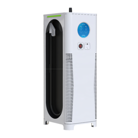
2. Product Description 2.1 System Overview Figure 2.1.1 HD/Touch screen with 22.5 cm diameter (HMI) LED Indicator Emergency button Charging plug Control panel with RFID/Credit card reader Cable holder Air inlet Air outlet Table 2.1.1 Housing and elements outside Copyright | C6AM User Manual, Version 1.2.2... - Page 10 This manual is valid for all the C6AM Versions, which are shown below in Table 2.1.2. Power Max. output Max. input DC CCS Combo CHAdeMO module Type power current 1 plug plug (30kW) 95kW 300A 200Ax1 125Ax1 C6AM-150- JC(208V) 150kW 200A 200Ax1 125Ax1...
-
Page 11: Charging Plug System
2.2 Charging Plug System CHAdeMO CCS Combo 1 Figure 2.2 Structure of charging plug, CHAdeMO and CCS Combo 1 Copyright | C6AM User Manual, Version 1.2.2... -
Page 12: Technical Data
3. Technical Data 3.1 Nameplate Figure 3.1.1 Nameplate (for reference only) Nameplate contains all the necessary information includes: - Product type and serial number - Input power and wiring - DC rated output voltage, current and power - Manufacturing date 3.2 Electrical Data Input 3 phase 208 V... -
Page 13: Mechanical Data
200 – 1000 V (Combo-1) Output voltage range 200 A continuously (Combo-1) Maximum output current Harmonic component 5% < in 50 – 100% of rated output power DC output (J) Maximum output power 60 kW 200 – 500 V (CHAdeMO) Output voltage range 125 A (CHAdeMO) -
Page 14: Technical Standards
Ingression protection IP54 Temperature range – Operation -20 °C to +50 °C Temperature range – De-rating +50 °C to +70 °C Temperature range - Storage -40 °C to +80 °C Operating Relative Humidity 5%-95%, no condensing on the surface Storage Relative Humidity 95%, no condensing on the surface Humidity Up to 95% no condensation on the surface... -
Page 15: Electrical Diagram
3.6 Electrical Diagram Circuit diagram: Figure 3.6.1 Electrical connection diagram Figure 3.6.2 Fans’ control diagram Notes: The diagram was already approved by TÜV Rheinland according to Standard EN 61851-23. For different types of C6AM the size of cable in the electrical connection diagram is variable. Copyright | C6AM User Manual, Version 1.2.2... -
Page 16: Function Structure Of C6Am
3.7 Function Structure of C6AM The Figure 3.7.1 below introduces the structure of C6AM from basic to sophisticated functions Figure 3.7.1 Copyright | C6AM User Manual, Version 1.2.2... -
Page 17: C6Am Power Curve
3.8 C6AM Output Power vs Temperature Curve Figure 3.8 3.9 C6AM Power Curve Type Power curve (U/I) C6AM 150kW(480 Copyright | C6AM User Manual, Version 1.2.2... - Page 18 C6AM 60Kw(208V) C6AM 95kw(208V) Table 3.8.1 Copyright | C6AM User Manual, Version 1.2.2...
-
Page 19: Installation
4. Installation The product will be delivered to a warehouse by logistic company and handed over to the customer. Normally XCHARGE is not responsible for the transport of charger and delivery to final installation location. 4.1 Required Space for Placing and Maintaining The space that C6AM needs is calculated as follows: ... -
Page 20: Installation Environment
The height of the foundation is determined by the terrain of the site. Depending on rainfall and drainage a height between 15 cm and 30 cm above the ground is recommended by XCHARGE. Because of frost-proof the foundation must be about 80 cm deep under the ground. -
Page 21: Stainless Steel Frame
Notes: laying of power cables should be carried out in accordance with relevant national and industrial standards and specifications including construction quality, process, and technical standards. Cable selection specification shall be selected according to the type, power, voltage and current level of the equipment and the number of equipment installed. - Page 22 Upper side (to be connected to the bottom of charger): 4 x M12 bolts and 4 x M12 weld nuts (provided by XCHARGE) Figure 4.3.3 Bottom side (to be fixed onto the ground): 4 x M12 expansion bolts Figure 4.3.4...
-
Page 23: Power Supply And Power Cable
Left and right sides (3 x removable stainless-steel plates - one with reserved hole): 8 x M6 Philips flat head screws on each side (provided by XCHARGE) Figure 4.3.5 4.4 Power Supply and Power Cable Requirements for the power supply:... -
Page 24: Packaging And Unpacking
Here is the suggestion for the cable dimension of all types C6AM: Cable gland Power Cable dimension Maximum Input Current (diameter) 2 Power 3P 90A modules(480V) 3 Power 3P 135A modules(480V) 4 Power 3P 180A modules(480V) 3x150mm 5 Power 52-60mm 3P 225A 2x70 mm modules(480V) -
Page 25: Unpacking
4.5.2 Unpacking Remove the package to confirm that charging station is intact. Remove the outer wooden box with a crowbar Remove foam plastic protection Remove the inner shrink wrap WARNING risk of suffocation! Children are not allowed to play with plastic wrap and shrink wrap. Figure 4.5.2 4.6 Positioning and Wiring CAUTION... - Page 26 (for example from floor to Foundation). For 150kW because of the weight, a forklift is suggested by XCHARGE to apply. Please ensure that the body of C6AM stays stable during movement through crane or forklift to avoid the possible swinging, which may cause damage to the charger;...
- Page 27 Figure 4.6.2 WARNING Mortal danger due to electrocution! Contact with high power parts can result in electric shock, burns or death. Before working, please put on the required protection equipment such as protective clothing and gloves: - Disconnect the system from the power supply. - Make sure that the power supply is disconnected before and while working on installation.
-
Page 28: Verification Of Measurement Values
Figure 4.6.3 In case that the station will be connected with a LAN cable for the backend connection, this cable should be laid through waterproof gland on the bottom to the RJ45 Port on the A8 communication board, shown in Figure 4.6.4. (it’s suggested to use such soft flat LAN cable like in figure because of the limited place for installation. - Page 29 commissioning and operation. Measurement in 480Vac Measurement points on live side Unit Nominal value Specified range L1 to N Voltage 277 V ± 10% L2 to N Voltage 277 V ± 10% L3 to N Voltage 277 V ± 10% L1 to L2 Voltage 480 V...
-
Page 30: Commissioning And Operation
5. Commissioning and Operation 5.1 Power Up WARNING Mortal danger due to electrocution! Contact with high power parts can result in electric shock, burns or death. If the charger is firmly fixed on the foundation and the power supply has been properly applied, then the charging station can be powered up by turning on the main switch, which is located on the bottom left behind the front door. -
Page 31: Control Panel
5.2.2 Control Panel For the charger with non-touch screen please press the arrow buttons and home button based on the guides on display to choose the options on screen. Home button right Left arrow button Arrow button card reader Figure 5.2.2 Control panel WARNING Danger of life through wrong installation! Extension cables are not permitted according to IEC 61851-1. - Page 32 QR Code Figure 5.3.2 The explanation of keywords: Icon: the charging plug sign on screen; Overtime: There is no action or no proper operation from the user within specified time; RFID: Radio Frequency Identification card; Abnormal stop/ fully-charged stop: stop initiated by EVSE or EV; ...
- Page 33 2. Authentication passed, waiting for the 2. Authentication passed, waiting for the official charging process official charging process 3. Charging process 3. Charging process 4. The bill after charging 4. The bill after charging Copyright | C6AM User Manual, Version 1.2.2...
-
Page 34: Indicator Lights
Press home button on control panel to Press “OK” to conplete this charging process complete this charging process Figure 5.3.4 Screenshot of UI 5.4 Indicator Lights Above the respective cable suspension is a widely visible LED indicator, which shows different statuses of the charging station. -
Page 35: Fault Diagnosis
6. Fault Diagnosis Charging station is equipped with automatic diagnosis function, and the fault will be directly displayed on the screen and sent to backend. If the charging station is online, users can call customer service, we will arrange online engineer for remote repair charging fault. - Page 36 Grid 1018 L3-phase undervoltage Check grid input Grid 1023 Discharge check failure Check power module EVSE 1025 Insulation check failure Please contact XCHARGE EVSE 1080 Power module check Please contact XCHARGE EVSE failure 10A0 SPD warning Check SPD status EVSE...
- Page 37 Check whether the door is EVSE closed, check whether the access control spring is working and whether the cable is connected 4023 Power module failure Please contact XCHARGE EVSE 4025 The vehicle demand Check EV EVSE voltage exceeds power module rating...
-
Page 38: Maintenance
6005 Electromagnetic lock Please contact XCHARGE EVSE check failure Table 6.1 Notes: When scanning QR-code or sweeping NFC/RFID card to start charging and system shows self- test failure: due to the difference of EVs inlets, plug the socket again to ensure that the charging plug is in the right position and lock functions well. -
Page 39: Anti-Dust Net Replacement
CAUTION Anti-dust net is located at charging station air-inlet part, and please check the net every 3 months and conduct scheduled cleaning. If not, dust blockage may happen, causing internal components overheated. Anti-dust Net Replacement In order to change the anti-dust net in 10min, quick change method is applied. After opening the front door and lifting the lock bar, the cover will open, then wash, air-dry the net, install the anti- dust net and locks back. -
Page 40: Contact Information
326 North LBJ Drive, Suite 173, San Marcos, Texas, United States of America Tel: +86 010-57215988 Email: b@XCHARGE.com China Beijing XCHARGE Technology Co., Ltd. 12 Shuangyang Road Daxing District 100176 Beijing CHINA Tel: +86 010-57215988 Email: b@XCHARGE.com Copyright | C6AM User Manual, Version 1.2.2... - Page 41 FCC Information To whom it may concern, This device complies with part 15 of the FCC Rules. Operation is subject to the following two conditions: (1) This device may not cause harmful interference, and (2) this device must accept any interference received, including interference that may cause undesired operation.
Need help?
Do you have a question about the C6AM Series and is the answer not in the manual?
Questions and answers