
Subscribe to Our Youtube Channel
Related Manuals for ESAB Aristo Mig U5000i 400 V


Summary of Contents for ESAB Aristo Mig U5000i 400 V
- Page 1 Mig U5000i Aristot 400 V version Instruction manual 0459 291 201 GB 070920 Valid for serial no. 640- -xxx- -xxxx...
-
Page 2: Table Of Contents
1 DIRECTIVE ............2 SAFETY . -
Page 3: Directive
DIRECTIVE DECLARATION OF CONFORMITY ESAB AB, Welding Equipment, SE--695 81 Laxå, Sweden, gives its unreserved guarantee that weld- ing power source Mig U5000i, Mig U5000iw from serial number 620 (2006 w.20) are constructed and tested in compliance with the standard EN 60974--1/--2 and EN 60974--10 in accordance with the re- quirements of directive (2006/95/EC) and (2004/108/EEC). - Page 4 MALFUNCTION - - Call for expert assistance in the event of malfunction. READ AND UNDERSTAND THE INSTRUCTION MANUAL BEFORE INSTALLING OR OPERATING. PROTECT YOURSELF AND OTHERS! ESAB can provide you with all necessary welding protection and accessories. WARNING! Read and understand the instruction manual before installing or operating.
-
Page 5: Introduction
The power source is intended for use with the Feed 3004 or Feed 4804 wire feed units. All the settings are made from the wire feed unit or control box U8. ESAB’s accessories for the product can be found on page 20. Equipment The power source is supplied complete with terminating resistor, 5m return cable and instruction manual. -
Page 6: Installation
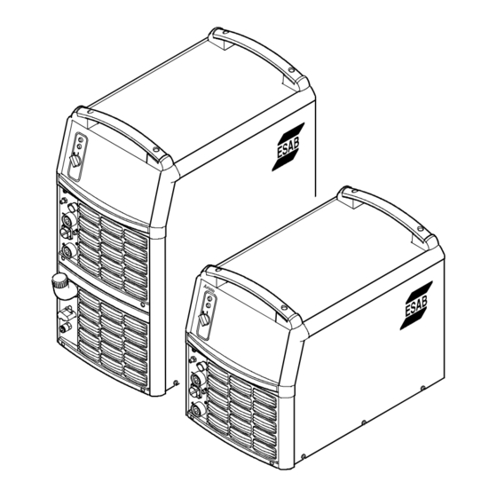
Mig U5000i Dimensions, lxwxh 625 x 394 x 496 mm with cooling unit 625 x 394 x 776 mm Continual sound pressure at no- -load <70 db (A) Weight 69 kg with cooling unit 89 kg Insulation class transformer Enclosure class IP 23 Application class Cooling unit... -
Page 7: Lifting Instructions
Lifting instructions Power source Trolley and power source Trolley2 and power source Placing Position the welding power source such that its cooling air inlets and outlets are not obstructed. Mains power supply Check that the unit is connected to the correct mains power supply voltage, and that it is protected by the correct fuse sizes. -
Page 8: Terminating Resistor
Terminating resistor In order to avoid communication interference, the ends of the CAN bus must be fitted with terminating resistors. One end of the CAN bus is at the control panel, which has an integral terminating resistor. The other end at the power source must be fitted with the terminating resistor, as shown on the right. - Page 9 Two wire feed units A connection kit is required when connecting two wire feed units, see accessories on page 20. Four wire feed units Two connection kits and an extra cooling unit are required when connecting four wire feed units, see accessories on page 20. - - 9 - - bu15d1ea...
-
Page 10: Operation
Connection for cooling water from the wire feed unit -- RED Connection for gas to the TIG torch Main power supply switch, 0 / 1 / START * ELP = ESAB Logic Pump, see point 6.5 - - 10 - - bu15d1ea... -
Page 11: Turning On The Power Source
Cooling unit Water connection (TIG welding) The cooling unit is equipped with a detection system ELP (ESAB Logic Pump) which checks that the water hoses are connected. The power source On/Off switch must be in the “0” position (Off) when connecting a water--cooled TIG torch. -
Page 12: Remote Control Unit
Remote control unit The program version in U8 should be 1.20 or higher. Machines with intergral control panels should have program version 1.21 or higher, in order for the remote control to function correctly. When the remote control unit is connected, the power source and wire feed unit are in remote control mode;... -
Page 13: Every Year
Replace the fan grille with the dust filter. Top up with coolant ESAB’s ready mixed coolant is recommended for use. See accessories on page 20. Top up with coolant until it covers half the inlet pipe. CAUTION! The coolant must be handled as chemical waste. -
Page 14: Fault Tracing
Repair and electrical work should be performed by an authorized ESAB serviceman. Use only ESAB original spare and wear parts. Spare parts may be ordered through your nearest ESAB dealer, see the last page of this publication. - - 14 - -... -
Page 15: Diagram
Diagram - - 15 - - bu15e11a... - Page 16 - - 16 - - bu15e11a...
- Page 17 Cooling unit - - 17 - - bu15e11a...
-
Page 18: Ordering Number
Mig U5000i 0459 230 886 Welding power source Mig U5000i with cooling unit 0459 291 990 Spare part list Mig U5000i The spare parts list is available on the Internet at www.esab.com - - 18 - - Edition 070920 bu15o11a... -
Page 19: Spare Parts List
Mig U5000i Spare parts list Item Ordering no. Denomination 0458 398 001 Filter 0458 383 001 Front grill - - 19 - - Edition 070920 ba37s... -
Page 20: Accessories
Mig U5000i Accessories Trolley ....... . . 0458 530 880 Trolley 2 (for feeder with counterbalance device and/or 2 gas bottles) . - Page 21 Mig U5000i Remote control adapter RA12 12 pole ..0459 491 910 For analogue remote controls to CAN based equipment. Remote control unit MTA1 CAN ..0459 491 880 MIG/MAG: wire feed speed and voltage MMA: current and arc force TIG: current, pulse and background current...
- Page 22 Mig U5000i Return cable 5 m 70 mm ....0700 006 895 Water flow guard 0.7 l/min ....0456 855 880 MMC kit for power source Mig .
- Page 23 - - 23 - -...
- Page 24 ESAB subsidiaries and representative offices Europe Asia/Pacific Representative offices NORWAY AS ESAB AUSTRIA BULGARIA CHINA Larvik ESAB Ges.m.b.H ESAB Representative Office Shanghai ESAB A/P Tel: +47 33 12 10 00 Vienna- -Liesing Sofia Shanghai Fax: +47 33 11 52 03...
Need help?
Do you have a question about the Aristo Mig U5000i 400 V and is the answer not in the manual?
Questions and answers