
Related Manuals for Unigas K890A


Summary of Contents for Unigas K890A
- Page 1 K750A K890A K990A LMV2x Microprocessor controlled Gas - Light oil burners MANUAL OF INSTALLATION - USE - MAINTENANCE BURNERS - BRUCIATORI - BRULERS - BRENNER - QUEMADORES - ГОРЕЛКИ M039497CB 0.4 06/2023...
-
Page 2: General Introduction
DANGERS, WARNINGS AND NOTES OF CAUTION THIS MANUAL IS SUPPLIED AS AN INTEGRAL AND ESSENTIAL PART OF THE PRODUCT AND MUST BE DELIVERED TO THE USER. INFORMATION INCLUDED IN THIS SECTION ARE DEDICATED BOTH TO THE USER AND TO PERSONNEL FOLLOWING PRODUCT INSTALLATION AND MAINTENANCE. -
Page 3: Directives And Standards
3b) FIRING WITH GAS, LIGHT OIL OR OTHER FUELS DIRECTIVES AND STANDARDS Gas burners GENERAL European directives The burner shall be installed by qualified personnel and in compliance -Regulation 2016/426/UE (appliances burning gaseous fuels) with regulations and provisions in force; wrong installation can cause -2014/35/UE (Low Tension Directive) injuries to people and animals, or damage to property, for which the -2014/30/UE (Electromagnetic compatibility Directive) -
Page 4: Symbols Used
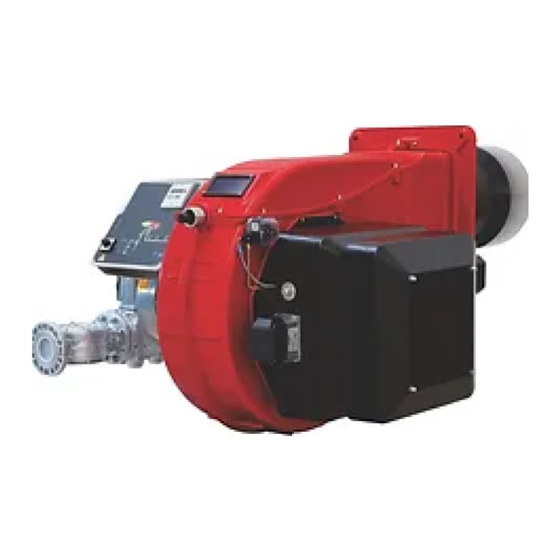
Burner data plate Type Gas - Light oil burners For the following information, please refer to Model Year European Directives the data plate: S.Number -Regulation 2016/426/UE (appliances burning gaseous fuels) burner type and burner model: must be Output Oil Flow -2014/35/UE (Low Tension Directive) reported in any communication with the Fuel... - Page 5 PART I: SPECIFICATIONS PART I: SPECIFICATIONS BURNERS FEATURES Note: the figure is indicative only Control panel with startup switch Gas train Electrical panel Cover Blast tube + Combustion head Flange Silencer Actuator Air pressure switch 10 Oil manifold 11 Pump Fig.
-
Page 6: Burner Model Identification
Burners are identified by burner type and model. Burner model identification is described as follows. Type K750A Model MD. SR. BURNER TYPE K750A- K890A - K990A MG - Natural gas - Light oil, LG - LPG Light oil FUEL OPERATION (Available versions) MD - Fully modulating - PR - Progressive BLAST TUBE... - Page 7 Overall dimensions (mm) Boiler recommended dril- ling template Burner flange 1672 946 1695 969 1745 366 1073 670 626 1215 524 1728 1002 M16 651 1808 1082 2073 1347 754 1192 479 1672 946 1695 969 1745 366 1073 670 626 1215 524 1728 1002 M16 651...
- Page 8 PART I: SPECIFICATIONS - 3I2MG-23 v0 Hydraulic diagram By others By burner constructor oil inlet oil outlet 19.1 combustion air M 48 gas inlet NOTE: The following items are optional: 19, 19.1, 20, 40, 41, 46 NOTE: The following items are included only on certain types of burner: 5,7,9,11,17 Flexible hose Flexible hose Manual valve...
-
Page 9: Performance Curves
Data are referred to standard conditions: atmospheric pressure at 1013 mbar, ambient temperature at 15° C. Performance Curves K750A K890A K990A To get the input in kcal/h, multiply value in kW by 860. Data are referred to standard conditions: atmospheric pressure at 1013mbar, ambient temperature at 15° C NOTE: The performance curve is a diagram that represents the burner performance in the type approval phase or in the laboratory tests, but does not represent the regulation range of the machine. - Page 10 Potenza / Output (kW) Pressure in the Network / gas flow rate curves (natural gas) K750A K890A K990A ATTENTION: the gas rate value is quoted on the x-axis, the related network pressure is quoted on the y-axis (pressure value in the combustion chamber is not included). To know the minimum pressure at the gas train inlet, necessary to get the requested gas rate, add the pressure value in the combustion chamber to the value read on the y-axis.
- Page 11 PART I: SPECIFICATIONS The values in the diagrams refer to GPL with a calorific value of 22300 kcal/Stm (15°C, 1013 mbar) and a density of 2.14 kg/ . When the calorific value and the density change, the pressure values should be adjusted accordingly. Natural gas pressure shown in diagram Where: Real gas pressure...
- Page 12 Pressure - rate in combustion head curves (natural gas) Curves are referred to pressure = 0 mbar in the combustion chamber! K750A K890A K990A The values in the diagrams refer to natural gas with a calorific value of 8125 kcal/Stm (15°C, 1013 mbar) and a density of...
-
Page 13: Transport And Storage
PART II: INSTALLATION PART II: INSTALLATION MOUNTING AND CONNECTING THE BURNER Transport and storage ATTENTION! The equipment must be installed in compliance with the regulations in force, following the manufac- turer’s instructions, by qualified personnel. All handling operations must be carried out with appropriate resources and qualified personnel ATTENTION: Use intact and correctly dimensioned hoisting equipment, conforms to the local regulations and health and safety regulations. - Page 14 PART II: INSTALLATION insulating material (ceramic fibre cord or refractory cement). Keys Burner Fixing nut Washer Ceramic fibre plait Stud bolt Blast tube Matching the burner to the boiler The burners described in this manual have been tested with combustion chambers that comply with EN676 regulation and whose dimensions are described in the diagram .
- Page 15 PART II: INSTALLATION GAS TRAIN CONNECTIONS The diagrams show the components of the gas train included in the delivery and which must be fitted by the installer.The diagrams are in compliance with the current laws. Note: the figure is indicative only ”direction”...
- Page 16 PART II: INSTALLATION MultiBloc MBE ALLA V. FARFALLA Example of gas train MBE 501939 GAS BRUCIATORE ø185 VD-R VD-V VD-R VD-V Gas filter PGMAX PGMAX PGMI PGMIN PS pressure sensor PGCP PGCP ATTENTION: once the gas train is mounted according, the gas proving test mus be performed, according to the procedure set by the laws in force.
- Page 17 PART II: INSTALLATION Mounting VD-R & PS-... ActuatorVD-V ActuatorVD-R M12 x 5 Pin The actuator VD-V does not need any adjustment (funzione ON-OFF) The actuator VD-R It must be combined with the PS sensor (include regolatore di pressione) VD-R + PS 1.
- Page 18 PART II: INSTALLATION SIEMENS VGD.. SKP1. SKP2. Mounting positions = BS PGMAX PGCP PGMIN Siemens VGD... con SKPx Example of gas train Gas filter version with SKP2 (built-in pressure stabilizer) Siemens VGD valves with SKP actuator: The pressure adjusting range, upstream the gas valves group, changes according to the spring provided with the valve group.
- Page 19 PART II: INSTALLATION Once the train is installed, connect the gas valves group and pressure switches plugs. Integrated proving system (burners equipped with LME7x, LMV, LDU) This paragraph describes the integrated proving system operation sequence: At the beginning both the valves (EV1 and EV2) must be closed. ...
- Page 20 PART II: INSTALLATION Installation diagram of light oil pipes please read carefully the “warnings” chapter at the beginning of this manual. Fig. 3 - Double-pipe system The burner is supplied with filter and flexible hoses, all the parts upstream the filter and downstream the return flexible hose, must be installed by the customer.
- Page 21 PART II: INSTALLATION ctions preferred. Junction threads, elbow joints and couplings should be sealed with removable sg component. The number of jun- ctions should be kept to a minimum as they are a possible source of leakage. Do not use PTFE tape on the suction and return line pipes to avoid the possibility that particles enter circulation. These could depo- ...
-
Page 22: Electrical Connections
PART II: INSTALLATION ELECTRICAL CONNECTIONS WARNING! Respect the basic safety rules. make sure of the connection to the earthing system. do not reverse the phase and neutral connections. fit a differential thermal magnet switch adequate for connection to the mains. WARNING! before executing the electrical connections, pay attention to turn the plant’s switch to OFF and be sure that the burner’s main switch is in 0 position (OFF) too. - Page 23 PART II: INSTALLATION BURNERS WITH INVERTER VARIANT (if provided) Type Model XXXXX M-. MD. xx. xx. x. x. xxx. EI. XXXXX M-. MD. xx. xx. x. x. xxx. EG. LMV5 DANFOSS XXXXX MG. MD. xx. xx. x. x. xxx. EK. XXXXX MG.
- Page 24 PART III: OPERATION PART III: OPERATION DANGER! Incorrect motor rotation can seriously damage property and injure people.WARNING: before starting the burner up, be sure that the manual cutoff valves are open and check that the pressure upstream the gas train complies the value quoted on paragraph “Technical specifications”.
-
Page 25: Gas Operation
PART III: OPERATION K750A - Burner front panel Keys B1 Lock-out LED B2 Hi-flame operation LED B3 Lo-flame operation LED B4 “Ignition transformer operation” LED B7 Burner ignition LED G1 “EV2 opening” LED G2 “EV1 opening” LED G3 “Gas pressure switch signal ” LED S4 Fuel selection S7 CMF switch (0=stop, 1=high flame,2=low flame, 3=automatic) -... -
Page 26: User Interface
PART III: OPERATION WARNING! During commissioning operations, do not let the burner operate with insufficient air flow (danger of formation of carbon monoxide); if this should happen, make the fuel decrease slowly until the normal combustion values are achieved. WARNING! the combustion air excess must be adjusted according to the values in the following chart. Recommended combustion parameters Recommended (%) CO Recommended (%) O... -
Page 27: Setting Menu
PART III: OPERATION Key F + A While pressing the two keys contemporarly, the code message will appear: by entering the proper password it is possible to access the Service mode. Info and Enter keys Used for Info and Service menues Used as Enter key in the setting modes Used as Reset key in the burner operation mode Used to enter a lower level menu... - Page 28 PART III: OPERATION User level (info): no password needed Service level (Service) Manifacturer level (OEM) PHASES LIST During operation, the following program phases are shown. The meaning for each phase is quoted in the table below Fase / Funzione Function Ph00...
-
Page 29: Info Level
PART III: OPERATION The burner and consequently the LMV2x.. are factory set; the air and fuel curves as set as well. Info level To enter the Info level, proceed as follows: in any menu position, press keys + and - at the same time, then the program will start again: the display will show OFF. until the display will show InFo, Press the enter (InFo) key then il will show the first code (167) flashing, on the right side it will show the data entered. -
Page 30: Parameter Description
PART III: OPERATION Parameter Description Cubic meters of fule (resettable) Operating hours (resettable) Device operating hours Burners start-ups (resettable) Total number of start-ups Burner number (i.e. serial number) Software version Software date Device serial number Customer code Version Free Example: choose parameter 102 to show the date the display shows parameter 102 flashing on the left and characters ._._ on the right. -
Page 31: Service Level
PART III: OPERATION Diagnostic code (in the example “diagnostic code:3”). Record the codes and find out the fault in the Error table. To perform the reset, press InFo for one second: The unit displays an event which does not lead to shutdown. The display shows current error code c: alternating with diagnostic code d: Press InFo to return to the display of phases. -
Page 32: Adjustments For Gas Operation
PART III: OPERATION .the first parameter will be “954”: the percentage of flame is shown on the right. By pressinf + or - it is possible to scroll up/down the parameter list. Once the last parameter is accessed (143) by pressing + , the End message will blink. PressPress InFo for more than three seconds or for more than three seconds orto return to the normal display. -
Page 33: Pressure Taps
PART III: OPERATION MultiBloc MBE Regulation VD-R whith PS Setting scale is „Not“ linear! Various sensors available. Output pressure according to sensor‘s measuring range. Increasing pressure Adjust the outlet pressure to the value specified by the burner or equipment manufacturer! While making outlet pressure adjustments, do not exceed a value that creates a hazardous condition to the burner! - Page 34 PART III: OPERATION Calibration air and gas pressure switches The air pressure switch locks the control box if the air pressure is not the one requested. If it happens, unlock the burner by means of the control box unlock pushbutton, placed on the bur- ner control panel.
- Page 35 PART III: OPERATION Adjusting the combustion head Attention! if it is necessary to change the head position, repeat the air and fuel adjustments described above. Only if necessary, change the combusiton head position: to let the burner operate at a lower output, loose the VB screw and move pro- gressively back the combustion head towards the MIN position, by turning clockwise the VRT ring nut.
- Page 36 PART III: OPERATION Adjustment procedure for light oil operation The light oil flow rate can be adjusted choosing a by-pass nozzle that suits the boiler/utilisation output and setting the delivery and return pressure values according to the ones quoted on the table below and the diagram on Fig. 20 (as far as reading the pressure values, see next paragraphs).
- Page 37 PART III: OPERATION Oil Flow Rate Settings Once the air and gas flow rates are adjusted, turn the burner off, switch to the oil operation (OIL, on the burner control panel). with the electrical panel open, prime the oil pump acting directly on the related CP contactor (see next picture): check the pump motor rotation and keep pressing for some seconds until the oil circuit is charged;...
- Page 38 PART III: OPERATION Minimum oil pressure switch (when provided) The minimum oil pressure switch on the inlet line, checks that the pressure does not drop below a default value. The pressure switch must be set, say, at 10% under the pressure at the nozzle. Maximum oil pressure switch The oil pressure switch on the return line, checks that the pressure does not exceed a default value.
- Page 39 PART IV: MAINTENANCE PART IV: MAINTENANCE WARNING: ALL OPERATIONS ON THE BURNER MUST BE CARRIED OUT WITH THE MAINS DISCONNECTED AND THE FUEL MANAUL CUTOFF VALVES CLOSED! ATTENTION: READ CAREFULLY THE “WARNINGS” CHAPTER AT THE BEGINNIG OF THIS MANUAL. At least once a year carry out the maintenance operations listed below. In the case of seasonal servicing, it is recommended to carry out the maintenance at the end of each heating season;...
- Page 40 PART IV: MAINTENANCE Thecnical procedure of self cleaning filters substitution (valid for all models) 1 Close the bowl valve before the self cleaning filter 2 Switch off any electrical equipment on board on the filter (example motorization or heaters) WARNING! Drain the system by unscrewing the drain screw on the bottom of the self cleaning filter 3 Disconnect the outlet pipe from the cover of the self cleaning filter 4 Remove the cover with all the filter pack, leaving only the bowl on the line 5 Clean any residue on the bottom of the bowl and clean the seat of the O-ring seal...
-
Page 41: Electrodes Adjustment
PART IV: MAINTENANCE 1 Inlet 2 Return 3 Gun opening E Oil piping connections H Cover Oil gun Center head holes gas flow regulation (LPG burners) To adjust the gas flow, partially close the holes, as follows: loosen the three V screws that fix the adjusting plate D; insert a screwdriver on the adjusting plate notches and let it move CW/CCW as to open/close the holes;... -
Page 42: Seasonal Stop
PART IV: MAINTENANCE Caution: adjust the nozzle position according to the air pipe, by means of the VU screw, ance the VL screw is fastened. Checking the detection current with electrode (natural gas) To check the detection signal follow the scheme in the picture below. If the signal is less than the value indicated, check the position of the detection electrode or detector, the electrical contacts and, if necessary, replace the electrode or the detector. - Page 43 PART IV: MAINTENANCE TROUBLESHOOTNG GUIDE Gas operation * No electric power supply * Restore power supply * Main switch open * Close switch * Thermostats open * Check set points and thermostat connections * Bad thermostat set point or broken thermostat * Reset or replace the thermostat * No gas pressure * Restore gas pressure...
- Page 44 PART IV: MAINTENANCE * No electric power supply * Wait for electric power supply is back * Main switch open * Close the switch * Thermostats open * Check set points and thermostat connections * Bad thermostat set point or broken thermostat * Set or replace the thermostat * No gas pressure * Restore gas pressure...
- Page 48 C.I.B. UNIGAS S.p.A. Via L.Galvani, 9 - 35011 Campodarsego (PD) - ITALY Tel. +39 049 9200944 - Fax +39 049 9200945/9201269 web site: www.cibunigas.it - e-mail: cibunigas@cibunigas.it Note: specifications and data subject to change. Errors and omissions excepted.
- Page 49 AZL2x - LMV2x/3x Burner Management System Service manual 03/2023 M12916CD Rev. 3.4...
- Page 50 INDEX MICROPROCESSOR CONTROLLED SYSTEM..........................6 User interface....................................6 Parameters level (heating engineer)............................... 8 Setting menu....................................9 Block 000: Internal Parameter ..............................10 Block 100: General information..............................10 Block 200: Burner control................................13 Block 400: Setting air/fuel ratio curves............................25 Block 500: Air/fuel ratio control ..............................26 Block 600: Actuators ..................................
-
Page 51: Special Warnings
DANGERS, WARNINGS AND NOTES OF CAUTION THIS MANUAL IS SUPPLIED AS AN INTEGRAL AND ESSENTIAL PART OF THE PRODUCT AND MUST BE DELIVERED TO THE USER. INFORMATION INCLUDED IN THIS SECTION ARE DEDICATED BOTH TO THE USER AND TO PERSONNEL FOLLOWING PRO- DUCT INSTALLATION AND MAINTENANCE. - Page 52 DIRECTIVES AND STANDARDS do not leave the equipment exposed to weather (rain, sun, etc.) unless expressly required to do so; Gas burners European directives: do not allow children or inexperienced persons to use equipment; - Directive 2009/142/EC - Gas Appliances; The unit input cable shall not be replaced by the user.
-
Page 53: National Standards
-EN 55014-1Electromagnetic compatibility - Requirements for household appliances, electric tools and similar apparatus. -UNI EN 676 (Gas Burners; -CEI EN 60335-1(Household and similar electrical appliances - Safety. Part 1: General requirements; - EN 50165 Electrical equipment of non-electric appliances for household and similar purposes. - Page 54 MICROPROCESSOR CONTROLLED SYSTEM The control system is made of the Siemens LMV central unit that performs all the burner control functions and of the Siemens AZL local programming unit that interfaces the system with the user. Keys Burner AZL2.. Air actuator Fuel actuator LMV2..
- Page 55 The keys functions are the following: Key F Used to adjust the “fuel” actuator position (Fuel): : While pressing the F key, the “fuel” actuator position can be changed by means of the + and - keys. Key A Used to adjust the “air” actuator position (Air): While pressing the A key, the “air”...
- Page 56 Parameters level (heating engineer)
- Page 57 Setting menu The seeting menu is divided into different blocks: Bloc. Descrizione Description Password Internal parameters OEM / Service Informazioni generali General OEM / Service / Info Controllo bruciatore Burner control OEM / Service Controllo bruciatore (solo LMV26) Burner control (LMV26 only) OEM / Service Curve rapporto Ratio curves...
- Page 58 Block 000: Internal Parameter Param. Descrizione Description Password Password livello assistenza (ingegnere del Password heating engineer (4 characters) calore) Password livello OEM (costruttore del brucia- Password OEM (5 characters) tore) Start backup / restore via AZL2.../ PC sof- tware (set parameter to 1) Index 0: Create backup Index 1: Execute restore Error dia- Start backup/restore via AZL2x/PC gnostics via negative values...
- Page 59 Frequenza di rete Mains frequency 0 = 50 Hz 0 = 50 Hz Service / Info 1 = 60 Hz 1 = 60 Hz Luminosità display Display brightness Service / Info Tempo dopo il quale, se non viene premuto nessun tast il software esce dalla modalita Timeout for menu operation (default value = programmazione (valore fabbrica = 60min - 60min - range: 10 - 120 min)
- Page 60 Numero totale di partenze (non azzerabile) Total number of startups Service / Info Volume combustibile (azzerabile da OEM) Fuel volume (resettable by OEM) Service / Info Fuel 1(secondo combustibile)Ore di eserci- Fuel 1: Operation hours resettable Service / Info zio (azzerabile da Service) Fuel 1 (secondo combustibile) Numero di Fuel 1: Number of startups resettable Service / Info...
- Page 61 Block 200: Burner control Param. Descrizione Description Password Modalità funzionamento bruciatore ( rampa Burner operating mode (fuel train, modula- combustibile, modulante / multistadio, servo- ting / multistage, actuators, etc..) comandi, ecc.) __= non definito (cancellazione curve) __= undefined (delete curves) 1 = accensione diretta a gas (G mod) 1 = gas direct ignition (G mod) 2 = accensione tramite pilota gas con attacco...
- Page 62 15 = gas rampa Gp1 modulante pneumatico 15 = Gp1 mod pneu without actuator senza servomotori (Gp1 mod pneu) 16 = Gp2 mod pneu without actuator 16 = gas rampa Gp2 modulante pneumatico 17 = Lo 2-stage without actuator senza servomotori (Gp2 mod pneu) 18 = Lo 3-stage without actuator 17 = olio LO 2 stadi senza servomotori 19 = G mod gas actuator only...
- Page 63 Gas: sonda rilevazione fiamma attivo (valore Gas: active detector flame evaluation (default fabbrica = 1) value = 1) OEM / Service 0 = QRB../QRC.. 1 = ION / QRA.. Gas: Preventilazione (valore fabbrica = 1) Gas: Pre-purging (default value = 1) 1 = attivo 1 = active 0 = non attivo...
- Page 64 Gas: Pressostato gas di minima (default = 1) Gas: Pressure switch-min input 0 = inattivo 0 = inactive 1 = pressostato gas di minima (a monte val- 1 = pressure switch-min (upstream of fuel vola V1) valve 1 (V1)) 2 = controllo perditavalvole via pressostato 2 = valve proving via pressure switch-min OEM / Service (montato tra le valvole V1 e V2)
- Page 65 Gas: tempo pressione atmosferica controllo Gas: proving test time atmospheric pres- tenuta (valore fabbrica = 10s - range impo- sure (default value = 10s - range:0.2s - 60s) stazione:0.2s - 60s) Gas: tempo riempimento controllo tenuta Gas: proving test filling time (default value = (valore fabbrica = 3s - range imposta- 3s - range:0.2s - 10s) zione:0.2s - 10s)
- Page 66 Olio: Intervallo 1 (valore fabbrica = 2s - Oil: Interval 1 (default value = 2s - OEM / Service range impostazione:0.2s - 60min) range:0.2s - 60min) Olio: tempo di sicurezza 2 (TSA2) (valore Oil: safety time 2 (TSA2) (default value = 3s fabbrica = 3s - range impostazione:0.2 - 10s) - range:0.2 - 10s) Olio: Intervallo 2 (valore fabbrica = 2s -...
- Page 67 Block 300: Burner control (only with LMV26) Param. Descrizione Description Password Combustibile 1 : Modalità funzionamento bru- Fuel 1 : Burner operating mode (fuel train, ciatore ( rampa combustibile, modulante / modulating / multistage, actuators, etc..) multistadio, servocomandi, ecc.) __= non definito (cancellazione curve) __= undefined (delete curves) 1 = accensione diretta a gas (G mod) 1 = gas direct ignition (G mod)
- Page 68 11 = olio 2 stadi con accensione tramite pilota 11 = LoGp 2-stage (LOGp 2-stage) 12 = Lo mod 2 fuel valves 12 = olio modulante con 2 valvole combusti- 13 = LoGp mod 2 fuel valves bile (LOmod 2 valvole) 14 = G mod pneu without actuator 13 = olio modulante con 2 valvole combusti- 15 = Gp1 mod pneu without actuator...
- Page 69 Combustibile 1 - Gas: tempo di preaccen- Fuel 1 - Gas: Preignition time (default value = sione (valore fabbrica = 2s - range imposta- 2s - range: 0.2s - 60min) OEM / Service zione:0.2s - 60min) Combustibile 1 - Gas: tempo di sicurezza 1 Fuel 1 - Gas: Safety time 1 (TSA1) (default (TSA1) (valore fabbrica = 3s - range impo- value = 3s - range: 0.2 - 10s)
- Page 70 Limite ripetizioni perdita di fiamma (valore Repetition limit loss of flame (default value= 2 fabbrica = 2 - range impostazione:1 - 2) - range:1 - 2) Fuel 1 - Gas: execution proving test (default Combustibile 1 - Gas: esecuzione controllo value= 2) tenuta (valore fabbrica = 2) 0 = no controllo tenuta...
- Page 71 Fuel 1 - Oil: prepurging (default value = 1) Combustibile 1 - Olio: preventilazione (valore fabbrica = 1) 0 = deactivated 1 = attivo 1 = activated 0 = non attivo 0 = deactivated OEM / Service In ambito civile la norma EN267 rende obbli- WARNING: in the civil field, the prepurge is gatoria la preventilazione.
- Page 72 Limite ripetizioni perdita di fiamma (valore Repetition limit value loss of flame (default fabbrica = 2 - range impostazione:1 - 2) value = 2 - range:1 - 2) Fuel 1 - Oil: time oil ignition (default value = Combustibile 1 - Olio: tempo iniezione olio (valore fabbr.
- Page 73 Block 400: Setting air/fuel ratio curves Param. Descrizione Description Password Curve controllo servocomando combustibile Ratio control curve fuel actuator (F): it acces- (F): si accede alla lista dei punti da impostare ses to the parameter list of the points to be set OEM / Service (da P0 a P9) - consultare paragrafo “Imposta- (P0 to P9) - see paragrapf “Setting the curves”...
- Page 74 Block 500: Air/fuel ratio control Param. Descrizione Description Password No-flame position fuel actuator Posizione servocomando combustibile in assenza di fiamma (no-flame) Indice 0 = posizione di sosta = 0° Index 0 = no-load position = 0° OEM / Service Indice 1 = posizione preventilazione = 0° Index 1 = prepurge position = 0°...
- Page 75 Activation of VSD / PWM fan (PWM = Pulse- Width Modulation) Activation of VSD / PWM fan OEM / Service 0=deactived 1=actived (PWM = Pulse-Width Modulation) Parameter 544 Modulation Modulation Modulation Modulation Actuator Actuating speed param- Max. delta between the curve points eter 613 OEM / Service Actuator...
- Page 76 Block 600: Actuators Param. Descrizione Description Password Impostazione punto di riferimento Selection of reference point Indice 0 = combustibile Index 0 = fuel Indice 1 = aria Index 1 = air 0 = chiuso (<0°) 0 = closed (<0°) 1 = aperto (>90°) 1 = open (>90°) Direzione rotazione del servocomando Actuator’s direction of rotation...
- Page 77 Tipo di riferimento dei servocomandi index 0 = fuel (default = 0 (riferimento stan- dard) Type of referencing index 1 = air (default = 0 (riferimento stan- Index 0 = fuel dard) Index 1 = air 0 = standard 0 = standard 1 = fermo entro il raggio utile 1 = stop within usable range 2 = fermi interni (SQN1...)
- Page 78 Configurazione uscita analogica % di carico Configuration of analog output (default value (valore fabbrica = 0) = 0) 0 = DC 0..10 V 0 = DC 0..10 V OEM / Service 1 = DC 2..10 V 1 = DC 2..10 V 2 = DC 0/2..10 V 2 = DC 0/2..10 V ATTENTION: as for SQM3x actuators, set the direction according to the acutator function.
- Page 79 Block 700: Error history Param. Descrizione Description Password Storico errori: 701 - 725.01.codice Error history: 701 - 725.01.code Service / Info Storico errori: 701 - 725.02.codice diagnostico Error history: 701 - 725.02.diagnostic code ° Service / Info Storico errori: 701 - 725.03.classe errore Error history: 701 - 725.03.error class °...
- Page 80 Block 900: Process data Param. Descrizione Description Password Potenza attuale (valore fabbrica = 0% - range Current output (default value = 0% - range = impostazione = 0-100%) 0-100%) Service / Info Indice 0 = combustibile Index 0 = fuel Indice 1 = aria Index 1 = air Posizione incrementale servocomandi (valore...
- Page 81 Actuators references An incremental transducer is used to ensure position feedback. Referencing of the actuators must be performed after power-on. In addition, at the end of each shutdown in phase 10, the actuators are referenced to ensure that individual stepping errors, which could lead to shutdown, do not accumulate.
-
Page 82: Commissioning The Burner
COMMISSIONING THE BURNER The LMV2x complete programming must be performed on units that has never been set before or reset units (e.g. spare parts). The programming procedure is performed by setting the following main parameters: if LMV.. is a spare part, insert burner ID (parameter 113) at least 4 digit. type of fuel train (parameter “201”) air/fuel ratio curvepoints (Block “400”) maximum load percentage (parameter “546”) - Page 83 the types of fuel trains are the following: Param. Descrizione Description Password Modalità funzionamento bruciatore ( rampa Burner operating mode (fuel train, mod / multi- comb., mod. / multistadio, servocom., ecc.) stage, actuators, etc.) __= non definito (cancellazione curve)___= __= undefined (delete curves) 1 = accensione diretta a gas (G mod) 1 = gas direct ignition(G mod) 2 = accensione tramite pilota gas con attacco...
- Page 84 Lo 3-stage In the example the Gmod gas train has been set (Configuration “1”). Choose the fuel train by pressing ENTER, then press “+” / “-”. Press ENTER to confirm: number “1” will appear on the right side of the display.
- Page 85 CAUTION: at the first burner adjustment, it is recommended to set the maximum output P9 at the same value (or little higher) of the ignition point, in order to safely reach point P9 next (see next paragraph). By pressing “+” the display will show: The burner is ready to startup.
-
Page 86: Warm Setting
Warm setting Once pressed button “enter” and the chain thermostats open (X5-03 terminals), the LMV.. show Ph12.Then close the chain termostat and the unit performs the prepurge cycle (see “Phases List”) and stops at the ignition point P0 without ignition anyway. By pressing “+”, the burners lights abd the air/fuel ratio can be properly set in presence of flame. -
Page 87: Cold Setting
P5, keep pressing “-” unitl “Calc” is displayed. The curve will be processed again downwards point P1. Fuel deviation between two following points: 25°max. 12 press “-” to go through the lower points and check the combustion values, if necessary change the points as described above. 13 By pressing ESC, at the end of the points adjusments, the parameter “546”... - Page 88 BURNER STARTUP WITH LMV2x ALREADY PROGRAMMED Once the LMV turns on, the AZL display will show The burners is basically factory set. The air/fuel ratio curve is set with the maximum output point P9 a little higher or equal to P0. To adjust the burner on the plant site, adjust the maximum output point to the flow rate values really requested.
- Page 89 Set the air/fuel ratio curvepoints as described on chapter “Programming the LMV2x” Note: the other phases are Ph60 = operation (OP= in modulation) Ph62 = travelling to shutdown Ph70 = off but in prepurge after the burntime Ph72 = travelling to postpurging Ph74 = postpurge (countdown is displayed) Press ESC the parameter “546”...
- Page 90 Reset / manual lockout The system can be manually locked by simultaneously pressing the ENTER (InFo) button and any other button on the AZL2..This function allows the user to stop the system from the operating level should an emergency occur. When making a reset, the following actions are carried out: Alarm relay and the fault display are off ...
- Page 91 Entering the Parameter levels By means of a proper use of the keys, it is possible to enter the various level parameters, as shown in the following flow chart: The burner and consequently the LMV2x.. are factory set; the air and fuel curves as set as well.
- Page 92 Info level To enter the Info level, proceed as follows: in any menu position, press keys + and - at the same time, then the program will start again: the display will show OFF. , until the display will show InFo, Press the enter (InFo) key then il will show the first code (167) flashing, on the right side it will show the data entered.
- Page 93 10 Press InFo for more than three seconds or for more than three seconds orto return to the normal display. If a message like the one below is shown during operation, it means that the burner is locked out and the Errore code is shown (in the example “error code:4”); this message is alternating with another message Diagnostic code (in the example “diagnostic code:3”).
- Page 94 Service level To enter the Service mode, press InFo until the display will show: The service level shows all the information about flame intensity, actuators position, number and lock codes: Parameter Description Flame intensity % output, if set = automatic operation Actuators position, 00=combustibile;...
- Page 95 PHASES LIST Fase /Phase Funzione Function Ph00 Fase blocco Lockout phase Ph01 Fase di sicurezza Safety phase Ph10 t10 = tempo raggiungimento posizione riposo t10 = home run Ph12 Pausa Standby (stationary) t22 = tempo di salita ventilatore (motore ventilatore t22 = fan ramp up time (fan motor = ON, safety Ph22 = ON, valvola intercettazione di sicurezza = ON)
- Page 96 BACKUP PARAMETER WITH AZL2x On the AZL2x you can save the configuration to download on another appliance LMV. To do this: access up, press F and A at the same time enter the password following the procedure on chapter “Programming LMV2x”. Press ENTER until the display will show: with the button go to the group 000 of the parameters and press...
- Page 97 RESTORE PARAMETER FROM AZL2x TO LMV.. To copy the previously saved configuration on AZL2x proceed as follows: access up, press F and A at the same time enter the password following the procedure on chapter “Programming LMV2x”. Press ENTER until the display will show: To copy the configuration from AZL2x to LMV.
- Page 98 ERROR CODE TABLE...
- Page 113 WIRING DIAGRAM Wiring connection for LMV20 Electrical supply Burner flange Fanmotor input Safety loop Lokout signal Continuous fan operator Valve External valveSV gnition transformer Valve Operation sgnal Reset Reserve Common Increase output Pressure switch leakage test Decrease input gasPGCP ON/OFF thermosta Minimum gas pressure switch Air pressure switch LUFT...
- Page 114 Wiring variants for LMV27 ConnectorX75 2 - Fuel meter input 1 - Supply fuel meter ConnectorX5-02 ConnectionsPmax...
- Page 115 Wiring variants for LMV26 ConnectorX08-04 / X09-04 2 - Fuel 0 1 - Fuel1 ConnectorX75 2 - Fuel meter input 1 - Supply fuel meter ConnectorX64 5 -Power supply speed sensor 4 -Speed sensor input 3 - PWM (Pulse Width Modulation) speed output 2 - GND (signal reference) 1 -Controller input (4÷20mA) ConnectorX74...
- Page 116 Wiring variants for LMV37 ConnectorX75 2 - Fuel meter input 1 - Supply fuel meter ConnectorX5-02 Connections Pmax ConnectorX64 5 -Power supply speed sensor 4 -Speed sensor input 3 - PWM (Pulse Width Modulation) speed output 2 - GND (signal reference) 1 -Controller input (4÷20mA) ConnectorX74 5 -Supply...
- Page 120 C.I.B. UNIGAS S.p.A. Via L.Galvani, 9 - 35011 Campodarsego (PD) - ITALY Tel. +39 049 9200944 - Fax +39 049 9200945/9201269 web site: www.cibunigas.it - e-mail: cibunigas@cibunigas.it Note: Specifications and and data subject to change. Errors and omissions excepted.
- Page 121 QF-A QF-B...
- Page 129 QF-A QF-B...
Need help?
Do you have a question about the K890A and is the answer not in the manual?
Questions and answers