Unigas K750A Manual
Hide thumbs
Also See for K750A:
- Manual of installation - use - maintenance (133 pages) ,
- Installation manual (112 pages)

Subscribe to Our Youtube Channel
Related Manuals for Unigas K750A


Summary of Contents for Unigas K750A
- Page 1 K750A K890A K990A Газовые горелки ИНСТРУКЦИЯ ПО МОНТАЖУ - ЭКСПЛУАТАЦИИ - ОБСЛУЖИВАНИЮ BURNERS - BRUCIATORI - BRULERS - BRENNER - QUEMADORES - ГОРЕЛКИ M039462NB 0.1 11/2021...
- Page 2 ПРЕДУПРЕЖДЕНИЯ И ПРИМЕЧАНИЯ, НА КОТОРЫЕ НЕОБХОДИМО ОБРАТИТЬ ВНИМАНИЕ: -НАСТОЯЩАЯ ИНСТРУКЦИЯ ПО МОНТАЖУ, ЭКСПЛУАТАЦИИ И ОБСЛУЖИВАНИЮ ЯВЛЯЕТСЯ НЕОТЪЕМЛЕМОЙ И ВАЖНОЙ ЧАСТЬЮ ИЗДЕЛИЯ И ДОЛЖНА БЫТЬ ПЕРЕДАНА ПОЛЬЗОВАТЕЛЮ. -НАСТОЯЩАЯ ИНСТРУКЦИЯ ПРЕДНАЗНАЧЕНА КАК ДЛЯ ПОЛЬЗОВАТЕЛЯ, ТАК И ДЛЯ ПЕРСОНАЛА, ОСУЩЕСТВЛЯЮЩЕГО МОНТАЖ, ВВОД В ЭКСПЛУАТАЦИЮ И ОБСЛУЖИВАНИЕ. -ИНФОРМАЦИЯ...
- Page 3 безопасности по действующему законодательству. предпринять меры к тушению пожара всеми возможными средствами. Использование любого компонента, потребляющего электроэнергию, требует соблюдения основных правил, таких Применение манометров: как: обычно манометры оснащены ручным или кнопочным краном. Открывать кран только для считывания, после чего...
- Page 4 топлива, имеющим электрические соединения) -UNI EN ISO 12100:2010 безопасность машин и механизмов, основные принципы конструирования, оценки риска и снижения -UNI EN ISO 12100:2010 безопасность машин и механизмов, риска. основные принципы конструирования, оценки риска и снижения риска. ЗАВОДСКАЯ ТАБЛИЧКА Для получения следующей информации всегда обращаться к заводской...
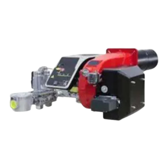
- Page 5 PART I: SPECIFICATIONS PART I: SPECIFICATIONS BURNERS FEATURES Note: the figure is indicative only Control panel with startup switch Gas train Electrical panel Cover Blast tube + Combustion head Flange Silencer Actuator Air pressure switch Sector variable Combustion head adjusting ring nut Gas operation The gas minimum pressure switch, installed upstream from the safety valves, ensures the network distributes the gas at a pressure sui- table to switch on the machine start cycle.
-
Page 6: Технические Характеристики
Горелки различаются по типу и модели. Маркировка моделей следующая. Тип K750A Модель MD. SR. ТИП ГОРЕЛКИ K750A, K890A, K990A M - Природный газ, L - Сжиженный газ ТИП ТОПЛИВА ИСПОЛНЕНИЕ (возможные варианты) MD - Модулирующее - PR - Прогрессивное СОПЛО SR = стандартное сопло; пластиковый воздухозаборник (АБС-пластик) СТРАНА... - Page 7 PART I: SPECIFICATIONS Country and usefulness gas categories GAS CATEGORY COUNTRY AT, ES, GR, SE, FI, IE, HU, IS, NO, CZ, DK, GB, IT, PT, CY, EE, LV, SI, MT, SK, BG, LT, RO, TR, CH LU, PL 2E( R ) B (*) I 2ELL (*) Only for I...
- Page 8 125 1840 366 626 1310 524 2073 1347 726 690 M16 651 754 1192 479 BS = standard blast tube BL = long blast tube DN = gas valves size B*: SPECIAL blast tube lengths must be agreed with Cib Unigas...
-
Page 9: Performance Curves
Power kW Potenza / Output (kW) Performance Curves K750A M- K890A M- K990A M- To get the input in kcal/h, multiply value in kW by 860. Data are referred to standard conditions: atmospheric pressure at 1013mbar, ambient temperature at 15° C NOTE: The performance curve is a diagram that represents the burner performance in the type approval phase or in the laboratory tests, but does not represent the regulation range of the machine. - Page 10 During the first ignition, the combustion head is set in order to find a compromise between the burner output and the generator specifications, that is why the minimum output may be different from the Performance curve minimum Pressure in the Network / gas flow rate curves(natural gas) K750A M- Gas rate Stm K890A M-...
- Page 11 (quoted on the y axis). The data obtained must be considered when adjusting the gas flow rate. Pressure - rate in combustion head curves (natural gas) Curves are referred to pressure = 0 mbar in the combustion chamber! K750A K890A K990A...
-
Page 12: Transport And Storage
PART II: INSTALLATION PART II: INSTALLATION MOUNTING AND CONNECTING THE BURNER Transport and storage ATTENTION! The equipment must be installed in compliance with the regulations in force, following the manufac- turer’s instructions, by qualified personnel. All handling operations must be carried out with appropriate resources and qualified personnel ATTENTION: Use intact and correctly dimensioned hoisting equipment, conforms to the local regulations and health and safety regulations. - Page 13 PART II: INSTALLATION Fitting the burner to the boiler To perform the installation, proceed as follows: drill the furnace plateas decribed in paragraph (“Overall dimensions”); place the burner towards the furnace plate: lift and move the burner by means of its eyebolts placed on the top side (see”Lifting and moving the burner”);...
- Page 14 PART II: INSTALLATION GAS TRAIN CONNECTIONS The diagrams show the components of the gas train included in the delivery and which must be fitted by the installer.The diagrams are in compliance with the current laws. Note: the figure is indicative only ”direction”...
- Page 15 PART II: INSTALLATION MultiBloc MBE ALLA V. FARFALLA Example of gas train MBE 501939 GAS BRUCIATORE ø185 VD-R VD-V VD-R VD-V Gas filter PGMAX PGMAX PGMI PGMIN PS pressure sensor PGCP PGCP ATTENTION: once the gas train is mounted according, the gas proving test mus be performed, according to the procedure set by the laws in force.
- Page 16 PART II: INSTALLATION Mounting VD-R & PS-... ActuatorVD-V ActuatorVD-R M12 x 5 Pin The actuator VD-V does not need any adjustment (funzione ON-OFF) The actuator VD-R It must be combined with the PS sensor (include regolatore di pressione) VD-R + PS 1.
- Page 17 PART II: INSTALLATION SIEMENS VGD.. Mounting positions = BS SKP1. SKP2. version with SKP2 (built-in pressure stabilizer) Siemens VGD valves with SKP actuator: The pressure adjusting range, upstream the gas valves group, changes according to the spring provided with the valve group. To replace the spring supplied with the valve group, proceed as fol- lows: - Remove the cap (T)
- Page 18 PART II: INSTALLATION Integrated proving system (burners equipped with LME7x, LMV, LDU) This paragraph describes the integrated proving system operation sequence: At the beginning both the valves (EV1 and EV2) must be closed. Test space evacuating: EV2 valve (burner side) opens and keep this position for a preset time ...
-
Page 19: Electrical Connections
PART II: INSTALLATION ELECTRICAL CONNECTIONS WARNING! Respect the basic safety rules. make sure of the connection to the earthing system. do not reverse the phase and neutral connections. fit a differential thermal magnet switch adequate for connection to the mains. WARNING! before executing the electrical connections, pay attention to turn the plant’s switch to OFF and be sure that the burner’s main switch is in 0 position (OFF) too. - Page 20 PART II: INSTALLATION BURNERS WITH INVERTER VARIANT (if provided) Type Model XXXXX M-. MD. xx. xx. x. x. xxx. EI. XXXXX M-. MD. xx. xx. x. x. xxx. EG. LMV5 DANFOSS XXXXX MG. MD. xx. xx. x. x. xxx. EK. XXXXX MG.
- Page 21 PART III: OPERATION PART III: OPERATION DANGER! Incorrect motor rotation can seriously damage property and injure people.WARNING: before starting the burner up, be sure that the manual cutoff valves are open and check that the pressure upstream the gas train complies the value quoted on paragraph “Technical specifications”.
-
Page 22: Gas Operation
PART III: OPERATION Fig. 1 - Burner front panel Keys Lock-out LED Hi-flame operation LED Lo-flame operation LED “Ignition transformer operation” LED “Fan motor overload tripped” LED “EV2 opening” LED “EV1 opening” LED “Gas pressure switch signal ” LED Main switch Operation selector MAN - AUTO (operation in manual or automatic mode): MIN = operation with minimum output MAX = operation at the maximum output... - Page 23 PART III: OPERATION Recommended combustion parameters Recommended (%) CO Recommended (%) O Fuel Natural gas 9 ÷ 10 3 ÷ 4.8 11 ÷ 12 2.8 ÷ 4.3 Adjustments - brief description Adjust the air and gas flow rates at the maximum output (“high flame”) first, by means of the air damper and the adjusting cam respec- tively.
- Page 24 PART III: OPERATION acting on the pressure stabiliser of the valves group, adjust the gas flow rate in the high flame stage as to meet the values requested by the boiler/utilisation: - Siemens VGD valves group: remove cap T and act on the VR adjusting screw to increase or decrease the pressure and consequently the gas rate;...
- Page 25 PART III: OPERATION Fully-modulating burners .To adjust the fully-modulating burners, use the CMF switch on the burner control panel (see next picture), instead of the TAB thermo- stat as described on the previous paragraphs about the progressive burners. Go on adjusting the burner as described before, paying attention to use the CMF switch intead of TAB.
-
Page 26: Pressure Taps
PART III: OPERATION Regulation VD-R whith PS MultiBloc MBE Setting scale is „Not“ linear! Various sensors available. Output pressure according to sensor‘s measuring range. Increasing pressure Adjust the outlet pressure to the value specified by the burner or equipment manufacturer! While making outlet pressure adjustments, do not exceed a value that creates a hazardous condition to the burner! Decreasing pressure... - Page 27 PART III: OPERATION Calibration air and gas pressure switches The air pressure switch locks the control box if the air pressure is not the one requested. If it happens, unlock the burner by means of the control box unlock pushbutton, placed on the bur- ner control panel.
-
Page 28: Routine Maintenance
PART IV: MAINTENANCE PART IV: MAINTENANCE WARNING: ALL OPERATIONS ON THE BURNER MUST BE CARRIED OUT WITH THE MAINS DISCONNECTED AND THE FUEL MANAUL CUTOFF VALVES CLOSED! ATTENTION: READ CAREFULLY THE “WARNINGS” CHAPTER AT THE BEGINNIG OF THIS MANUAL. At least once a year carry out the maintenance operations listed below. In the case of seasonal servicing, it is recommended to carry out the maintenance at the end of each heating season;... - Page 29 PART IV: MAINTENANCE MultiBloc MBE MultiBloc VD Mounting to push position 1. Position VD on VB, fig. 2+3. 2. Slide VD forward up to the stop, fig. 4. 3. Screw VD on with 2 M5 screws for each, max. 5 Nm/44 in.-lb., fig. 5/6. 4.
- Page 30 PART IV: MAINTENANCE Center head holes gas flow regulation (natural gas burners) To adjust the gas flow, partially close the holes, as fol- lows: loosen the three V screws that fix the adjusting plate D; insert a screwdriver on the adjusting plate notches and let it move CW/CCW as to open/close the holes; once the adjustmet is performed, fasten the V screws.
-
Page 31: Electrodes Adjustment
PART IV: MAINTENANCE Remove the burner cover C. Remove the electrode cables Unscrew the screws V holding in position the manifold G and pull out the complete group as shown in figure. Note: for the subsequent assembly carry out the above described operations in the reverse order, Fig. -
Page 32: Wiring Diagrams
PART IV: MAINTENANCE Flame detection probe To clean/replace the detection photocell, proceed as follows: Disconnect the system from the electrical power supply. Shut off the fuel supply; remove the photocell from its slot (see next figure); clean the bulbe if dirty, taking care not to touch it with bare hands; if necessary, replace the bulb;... - Page 33 PART IV: MAINTENANCE * No electric power supply * Restore power supply * Main switch open * Close switch * Thermostats open * Check set points and thermostat connections * Bad thermostat set point or broken thermostat * Reset or replace the thermostat * No gas pressure * Restore gas pressure BURNER DOESN'T LIGHT...
- Page 34 БЕЗОПАСНОСТЬ РАБОТЫ ГОРЕЛКИ Горелки и ниже описанные конфигурации – соответствуют действующим нормативам по безопасности в работе, защите здоровья и окружающей среды. Для получения более детальной информации — прочитать декларации по соответствию продукции, которые являются неотъемлемой частью данных инструкций. ОПАСНО! Предохранительные устройства и компоненты горелок изготовлены с целью защиты от возможных...
- Page 36 СЕРВИСНАЯ СЛУЖБА ООО "ЧИБ УНИГАЗ" (UNIGAS SERVICE) Авторизованный Сервисный Центр завода CIB UNIGAS S.p.A. на территории России и стран СНГ Техническая служба: 8-800-500-42-08 г. Москва email: service@cibunigas.com, г. Екатеринбург email: service-ekb@cibunigas.com По вопросам приобретения запасных частей: г.
- Page 37 LME73.000Ax + PME73.831AxBC LME73.831AxBC Инструкции для сервисной службы M12921NB Rel.1.2 02/2016...
-
Page 38: Общие Характеристики
ОБЩИЕ ХАРАКТЕРИСТИКИ Серия электронных блоков контроля пламени LME7… состоит из базовой части (hardware – жесткого диска) LME73.000 и второй части (software – программного обеспечения) с частью EEPROM PME73.831AxBC, где находится программа работы. Кроме того, имеется в наличии устройство LME73.831AxBC без дополнительной части EEPROM, с программой работы... - Page 39 Интерфейс потребителя: Кнопка A - визуализирует заданную мощность - В положении блокировки: значение мощности в момент аварии Кнопка Info и Enter - Сброс блокировки (Reset) в случае аварии Кнопка « – « - визуализирует ток сигнала пламени 2 или фазы - на...
- Page 40 Перечень фаз работы, отображаемых на дисплее контроллера LME: Номер фазы на дисплее LED - индикатор Функция с 7-ю сегментами Выжидание Off - Выкл Выжидание, ожидание запроса тепла Off - Выкл питание ON / фаза тестирования (нар. Тест на улавливание пламени) Пуск...
- Page 41 Работа: Кнопка сброса блокировки (Info) (EK) - является ключевым элементом для сброса блокировки контроллера LME73, а также для активации и дезактивации функций диагностики Iмногоцветные LED – индикаторы визуализируют диагностику. Кнопка сброса блокировки (EK) и сигнальные LED – индикаторы расположены на контрольной панели. Имеются...
- Page 42 Последовательность работы: Вариант 1: • Точка розжига < малого пламени • Продувка в режиме большого пламени • Параметр 515 = 1 (параметр 259.01 > 0 секунд)
- Page 43 Последовательность работы: Вариант 2: • Точка розжига > малого пламени • Продувка в режиме большого пламени • Параметр 515 = 1 (параметр 259.01 = 0 секунд)
- Page 44 Номер Функция фазы Фаза блокировки Пауза, ожидание запроса на тепло Работа, модуляция мощности Пауза до выдачи ориентира контроллера нагрузки (аналоговый вход или 3-х точечный) Под напряжением Разомкнута цепь защит Посторонний свет во время фазы пуска горелки (закончилось время/блокировка через 30 секунд) Питание...
- Page 45 Таблица кодов ошибок: Код красного мигания Возможная причина в случае аварии Отсутствие пламени в конце времени безопасной работы (TSA) - устройство улавливания пламени дефектно или загрязнено 2 x мигания - газовые клапаны загрязнены или дефектны - неправльная настройка горелки, отсутствие топлива - устройство...
- Page 46 Контроль (улавливание) пламени – контрольный электрод: Ток короткого замыкания Макс. Перем.ток 1 мA Требуемый ток контрольного электрода Мин. DC 2 μA, дисплей примерно 45% Возможный ток контрольного электрода Макс. DC 3 μA, дисплей примерно 100% Разрешаемая длина кабеля контрольного электрода 30 м...
- Page 47 Контроль газовых клапанов на герметичность: Контроль герметичности зависит от от подсоединения на соединительном разъеме X2-02 “реле давления газа для контроля за утечками ON/OFF” контакт NO контроля герметичности находится на ON, контакт NC контроля герметичности находится на OFF. Когда обнаруживается утечка газовых клапанов, на фазе контроля герметичности, функция “контроль герметичности” позволяет...
- Page 48 Инструкции по контролю модификаций через БУИ2x: Дисплей БУИ23.. или БУИ21.. в распоряжении Сервисной службы для конфигурации/изменения параметров. Дисплей Буи23 имеет следующий вид: Таблица функций кнопок Кнопки F и A Нажимая одновременно две кнопки на дисплее появляется надпись code и при написании соответствующего...
- Page 49 А дисплей может отображать эти данные: Блокировка + код блокировки Наличие пламени Открытые клапаны Введен в действие запальный трансформатор Введен в действие двигатель вентилятора Включен подогрев мазутного топлива Запрос на тепло со стороны системы На стадии программирования На стадии Info На...
- Page 50 Перечень фаз на дисплее БУИ2x: Номер фазы Функция Выжидание - Standby Выжидание запроса тепла Ph08 питание ON / фаза тестирования (напр. Тест блок а контроля пламени) Пуск Ph21 Предохранительные клапаны находятся на ON, тест реле давления воздуха/ POC тест Ph22 Двигатель...
- Page 51 Перечень кодов ошибок, получаемый через наружный БУИ2x: Код ошибки Tекст Возможная причина Loc 2 Отсутствие пламени в конце - газовые клапаны имеют дефект или загрязнены времени безопасной работы - устройство улавливания пламени имеет дефект или загрязнено (TSA) - неправильная настройка горелка, отсутствие топлива - устройство...
- Page 52 Доступ на уровни параметров: Доступ на разные уровни параметров можно осуществить с помощью соответствующих комбинаций клавиш, как это изображено на следующей схеме с блоками:...
- Page 53 Уровень Info: Нажать и держать в нажатом состоянии кнопку Info до тех пор, пока на дисплее не появится При нажатии на кнопку или кнопку можно передвигаться вперед или назад по перечню параметров. – Если справа появляется «точка–линия» - это означает, что не хватает места для полной визуализации. Нажимая...
- Page 54 Уровень Service – сервисной службы: Нажать и держать в нажатом состоянии кнопку Info до тех пор, пока на дисплее не появится Нажимая на конпку или кнопку можно передвигаться перед и назад по перечню параметров. – Если справа появляется «точка–линия» - это означает, что не хватает места для полной визуализации. Нажимая...
- Page 55 Уровень Параметров (Специалист - наладчик): Самый важный уровень параметров, потому что он позволяет наладчику горелок изменить некоторые, уже запрограммированные, данные горелки. Доступ к уровню параметров защищен паролем, состоящим из 4-х знаков (SO - наладчик) и паролем, состоящим из 5 знаков (OEM –...
- Page 56 Автоматический повторный запуск после блокировки из-за потери пламени во время работы изменяемое 0 = нет 1 = нет 2 = 1 x повтор Контроль герметичности газовых клапанов 241.00 0 = OFF изменяемое 1 = ON Контроль герметичности 0 = во время предварительной продувки (t1) 241.01 изменяемое...
- Page 57 ВНИМАНИЕ! Номер параметра: Параметры могут изменяться с соответствующих уровней доступа SO или OEM на контроллере LME73.831AxBC 259.01...
- Page 60 СЕРВИСНАЯ СЛУЖБА ООО "ЧИБ УНИГАЗ" (UNIGAS SERVICE) Авторизованный Сервисный Центр завода CIB UNIGAS S.p.A. на территории России и стран СНГ Техническая служба: 8-800-500-42-08 г. Москва email: service@cibunigas.com г. Екатеринбург email: service-ekb@cibunigas.com По вопросам приобретения запасных частей: г.
- Page 61 (Certificati EAC) www.cibunigas.com ЗАЯВИТЕЛЬ: Общество с ограниченной ответственностью "Чиб Унигаз" Сертификат Таможенного союза – Сертификат Таможенного союза RU C-IT.MX17.B.00061/19 N° 0101956 от 29-07-2019 до 28-07-2024 RU C-IT.MX17.B.00535 N° 0726892 от 08-08-2018 до 07-08-2023 RU C-IT.MX17.B.00063/19 N° 0101958 от 29-07-19 до 28-07-2024 RU C-IT.MX17.B.00564 N°...
Need help?
Do you have a question about the K750A and is the answer not in the manual?
Questions and answers