
Subscribe to Our Youtube Channel
Related Manuals for Unigas KP91


Summary of Contents for Unigas KP91
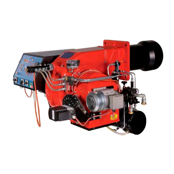
- Page 1 KP91 KP92 KP93 KR512 KR515 KR520 KR525 Gas - heavy oil burners MANUAL OF INSTALLATION - USE - MAINTENANCE BURNERS - BRUCIATORI - BRULERS - BRENNER - QUEMADORES - ГОРЕЛКИ M03940CL 0.0 06/2020...
-
Page 2: General Introduction
DANGERS, WARNINGS AND NOTES OF CAUTION THIS MANUAL IS SUPPLIED AS AN INTEGRAL AND ESSENTIAL PART OF THE PRODUCT AND MUST BE DELIVERED TO THE USER. INFORMATION INCLUDED IN THIS SECTION ARE DEDICATED BOTH TO THE USER AND TO PERSONNEL FOLLOWING PRODUCT INSTALLATION AND MAINTENANCE. -
Page 3: Directives And Standards
3b) FIRING WITH GAS, LIGHT OIL OR OTHER FUELS DIRECTIVES AND STANDARDS Gas burners GENERAL European directives The burner shall be installed by qualified personnel and in compliance -Regulation 2016/426/UE (appliances burning gaseous fuels) with regulations and provisions in force; wrong installation can cause -2014/35/UE (Low Tension Directive) injuries to people and animals, or damage to property, for which the -2014/30/UE (Electromagnetic compatibility Directive) -
Page 4: Symbols Used
Burner data plate Type Gas - Light oil burners For the following information, please refer to Model Year European Directives the data plate: S.Number -Regulation 2016/426/UE (appliances burning gaseous fuels) burner type and burner model: must be Output Oil Flow -2014/35/UE (Low Tension Directive) reported in any communication with the Fuel... -
Page 5: Burner Features
KR525 Model MD. S. (1) BURNER TYPE KP91 - KP92 - KP93 - KR512 - KR515 - KR520 - KR525 M - Natural gas, L - LPG E - Heavy oil, viscosity <= 110cSt (15°E) @ 50° C (2) FUEL D - Heavy oil, viscosity <= 400cSt (50°... - Page 6 PART I: SPECIFICATIONS BURNERS KP91 KP92 KP93 Output min. - max. kW 480 - 2670 480-3050 550 - 4100 Natural gasHeavy oil Fuel Category (see next paragraph) min. - max. (Stm 51 - 283 51 - 323 58 - 434 Gas rate min.
- Page 7 PART I: SPECIFICATIONS BURNERS KP91 L- KP92 L- KP93 L- Output min. - max. kW 480 - 2670 480-3050 550 - 4100 LD - L LPG - D Heavy oil, viscosity <= 400cSt (50° E) @ 50° C Fuel Category...
- Page 8 PART I: SPECIFICATIONS Country and usefulness gas categories COUNTRY CATEGORY ES GR SE NO CZ DK GB PT CY EE LV MT SK BG LT RO TR CH 2E( R ) B (*) I 2ELL (*) Only for I : the appliance was configured for the appliance category K (I2K) and is suitable for the use of G and G+ distribution gases according to the specifications as included in the NTA 8837:2012 Annex D with a Wobbe index of 43.46 –...
- Page 9 Overall dimensions (mm) KP91, KP92, KP93 Boiler recommended drilling template O min. O max. Reccomended burner flange 50 1615 152 221 473 429 100 560 441 1055 533 1455 464 859 441 596 304 344 228 329 360 466 M12 424 280 310 300 522 148 374...
- Page 10 KR512 Boiler recommended drilling template O min-max Reccomended burner flange AA AD AE AN AP 50 1766 229 35 313 594 100 555 508 1211 598 1585 407 943 476 642 380 420 354 540 560 M14 552 390 390 755 150 605 843 216 891 328 270 65 1766 229 35 313 612 118 555 508 1119 598 1609 407 967 476 642 380 420 354 540 560 M14 552 390 390 633 150 483 843 292 891 328 270 KR512 80 1766 229 35 313 626 132 555 508 1119 598 1644 407 1002 476 642 380 420 354 540 560 M14 552 390 390 685 150 535 875 322 891 328 270...
- Page 11 KR515, KR520 Boiler recommended drilling template O min-max Reccomended burner flange 1676 144 508 1146 598 1585 943 492 M14 552 1676 144 508 1146 598 1609 967 492 M14 552 1676 144 508 1146 598 1644 1002 642 492 M14 552 100 1676 144 508 1146 598 1727 1085 642 492 M14 552...
- Page 12 KR525 O min-max Reccomended burner flange Boiler recommended drilling template AA AD AN 1682 144 35 594 100 530 650 1152 598 1585 642 454 504 494 540 492 M14 552 390 390 755 150 605 843 216 759 343 270 1682 144 35 612 118 530 650 1152 598 1609 642 454 504 494 540 492 M14 552 390 390 633 150 483 843 292 759 343 270 1682 144 35 626 132 530 650 1152 598 1644 1002 642 454 504 494 540 492 M14 552 390 390 685 150 535 875 322 759 343 270...
- Page 13 KP91, KP92, KP93, KR512 Fig. 4 3I2MD11 v1 Hydraulic diagram BY OTHERS BY BURNER CONSTRUCTOR oil inlet oil outlet gas inlet combustion air inlet ATTENTION: connect the oil return line to the degassing bottle (standard UNI 9248), as shown in the chapter "Recommendations to design heavy oil feeding plants"...
- Page 14 KR515, KR520, KR525 Fig. 5 3I2MD15 v1 Hydraulic diagram BY OTHERS preassembling unit on a self standing skid BY BURNER CONSTRUCTOR oil inlet oil outlet gas inlet combustion air inlet ATTENTION: connect the oil return line to the degassing bottle (standard UNI 9248), as shown in the chapter "Recommendations to design heavy oil feeding plants"...
- Page 15 PART I: SPECIFICATIONS How to read the burner “Performance curve” To check if the burner is suitable for the boiler to which it must be instal- Campo di lavoro bruciatori lled, the following parameters are needed: Tipo P60 Mod. M-xx.x.IT.A.0.50 - M-.xx.x.IT.A.0.65 furnace input, in kW or kcal/h (kW = kcal/h/860);...
-
Page 16: Performance Curves
PART I: SPECIFICATIONS Performance Curves KP91 KP92 1200 1600 2000 2400 2800 3200 3600 KP93 1500 2500 3500 4500 KR512 KR515 1500 2500 3500 4500 5500 1500 2500 3500 4500 KR520 KR525 1500 2500 3500 4500 5500 6500 7500 1500... - Page 17 PART I: SPECIFICATIONS Pressure in the network - gas rate curves - natural gas KP91 KP92 Rp 2" (50) DN65 DN80 DN100 KP93 Rp 2" (50) DN65 DN80 DN100 KR512 KR515 Rp 2" (50) Rp 2" (50) DN65 DN65 DN80...
- Page 18 PART I: SPECIFICATIONS Combustion head gas pressure curves Combustion head gas pressure depends on gas flow and combustion chamber backpressure. When backpressure is subtracted, i depends only on gas flow, provided combustion is properly adjusted, flue gases residual O2 percentage complies with “Recommended combustion values”...
- Page 19 Pressure - rate in combustion head curves (natural gas) PART I: SPECIFICATIONS Curves are referred to pressure = 0mbar in the combustion chamber! KP91 KP92 40 60 80 100 120 140 160 180 200 220 240 260 280 300 320 340...
- Page 20 MOUNTING AND CONNECTING THE BURNER Packing The burners are despatched wooden cages whose dimensions: KP91-KP92-KP93: 1730mmx 1280mm x 1020mm (L x P x H) KR512-KR515-KR520-KR525: 1730mm x 1430mm x 1130mm (L x P x H) Packing cases of this kind are affected by humidity and are not suitable for stacking. The following are placed in each packing case: burner with gas train detached;...
- Page 21 PART II: INSTALLATION Fitting the burner to the boiler To install the burner into the boiler, proceed as follows: make a hole on the closing door of the combustion chamber as described on paragraph “Overall dimensions”) place the burner to the boiler: lift it up and handle it according to the procedure described on paragraph “Handling the burner”; place the 4 stud bolts (5) on boiler’s door, according to the burner drilling template described on paragraph “Overall dimensions”;...
- Page 22 PART II: INSTALLATION GAS TRAIN CONNECTIONS The diagrams show the components of the gas train included in the delivery and which must be fitted by the installer.The diagrams are in compliance with the current laws. Note: the figure is indicative only ”direction”...
- Page 23 PART II: INSTALLATION MultiBloc MBE ALLA V. FARFALLA Example of gas train MBE 501939 GAS BRUCIATORE ø185 VD-R VD-V VD-R VD-V Gas filter PGMAX PGMAX PGMI PGMIN PS pressure sensor PGCP PGCP ATTENTION: once the gas train is mounted according, the gas proving test mus be performed, according to the procedure set by the laws in force.
- Page 24 PART II: INSTALLATION Mounting VD-R & PS-... ActuatorVD-V ActuatorVD-R M12 x 5 Pin The actuator VD-V does not need any adjustment (funzione ON-OFF) The actuator VD-R It must be combined with the PS sensor (include regolatore di pressione) VD-R + PS 1.
- Page 25 PART II: INSTALLATION SIEMENS VGD.. SKP1. SKP2. Mounting positions = BS PGMAX PGCP PGMIN Siemens VGD... con SKPx Example of gas train Gas filter version with SKP2 (built-in pressure stabilizer) Siemens VGD valves with SKP actuator: The pressure adjusting range, upstream the gas valves group, changes according to the spring provided with the valve group.
- Page 26 PART II: INSTALLATION Once the train is installed, connect the gas valves group and pressure switches plugs. OIL TRAIN CONNECTIONS About the use of fuel pumps Do not use fuel with additives to avoid the possible formation over time of compounds which may deposit between the gear teeth, ...
- Page 27 PART II: INSTALLATION Rotation speed 3600 rpm max. 1. Connection for manometer 1 – delivery (M1) – G1/4 2. Connection for manometer 2 – suction (M2) – G1/4 3. Connection for manometer 3 (M3) A. Suction connection– G1/2 D. Direct - clockwise I.
- Page 28 Connecting the burner to the oil pumping unit PART II: INSTALLATION KR515, KR520, KR525 G1/2” G1/2” G3/4” Legend inlet return G1” G3/8” G1”...
- Page 29 PART II: INSTALLATION PLANT WITH DEGASING BOTTLE KP91, KP92, KP93, KR512 Legend inlet G1/2” G1” G1” G1/2” G1/2” G1” KR515, KR520, KR525 G1/2” G1/2” Legend inlet return G3/4” G1” G1/2” G1” G1/2” G1/2” G1”...
-
Page 30: Electrical Connections
PART II: INSTALLATION ELECTRICAL CONNECTIONS WARNING! Respect the basic safety rules. make sure of the connection to the earthing system. do not reverse the phase and neutral connections. fit a differential thermal magnet switch adequate for connection to the mains. WARNING! before executing the electrical connections, pay attention to turn the plant’s switch to OFF and be sure that the burner’s main switch is in 0 position (OFF) too. - Page 31 PART II: INSTALLATION ELECTRIC MOTOR CONNECTION 400 V 230V Connecting the oil heating resistors 2.4 - 4.5 kW 8 - 12 kW 400 V 230V 400 V 230V Fig. 4 Fig. 5 18 - 24 kW 400 V 230V Fig. 6...
- Page 32 PART II: INSTALLATION RECOMMENDATIONS TO DESIGN HEAVY OIL FEEDING PLANTS This paragraph is intended to give some suggestions to make feeding plants for heavy oil burners. To get a regular burner operation, it is very important to design the supplying system properly. Here some suggestions will be mentioned to give a brief description. The term “heavy oil”...
- Page 33 PART II: INSTALLATION Viscosity units conversion table Saybolt Cinematics Saybolt Redwood Engler Degrees Seconds Redwood Seconds viscosity Seconds Seconds no.1 (°E) Universal no..2 (Admiralty) Centistokes (cSt) Furol (SSF) (Standard) (SSU) 2.56 1.16 32.1 1.31 36.2 1.58 44.3 5.83 10.3 1.88 52.3 6.77 13.1...
- Page 34 PART II: INSTALLATION VISCOSITY vs TEMPERATURE DIAGRAM FOR COMBUSTIBLE OILS 1000 PUMPING LIMIT TEMPERATURE (°C) LIGHT OIL 1,3°E AT 20°C HEAVY OIL 2,4°E AT 50°C HEAVY OIL 4°E AT 50°C HEAVY OIL 7,5°E AT 50°C HEAVY OIL 10°E AT 50°C HEAVY OIL 13°E AT 50°C HEAVY OIL 22°E AT 50°C HEAVY OIL 50°C...
- Page 35 PART II: INSTALLATION Indicative diagram showing the oil temperature at burner pump inlet vs. oil viscosity Example: if the oil has a 50°E @ 50°C viscosity, the oil temperature at the pump inlet should be 80°C (see diagram). OIL TEMPERATURE FOR PUMP FEEDING TEMPERATURE (°C) Fig.
- Page 36 Fig. 11 3ID00014 v2 Hydraulic diagram - Two or more burners configuration BURNER 2 SEE THE BURNER 1 SEE THE BURNER P&ID BURNER P&ID HEATING MEDIUM INLET HEATING MEDIUM OUTLET PRESSURE GOVERNOR UNIT OIL PUMPING UNIT DAILY TANK UNIT OIL PUMPING UNIT PIPE HEATING SYSTEM: SEE THE SPECIFIC HEATING MEDIUM INLET MAIN TANK INLET...
- Page 37 Fig. 12 - 3ID0023 v2 - Hydraulic diagram - Single burner configuration BURNER 1 SEE THE BURNER P&ID OIL TRAIN Main tank OIL PUMPING UNIT Manual valve Filter Pump coupled to electrical motor Safety valve HEATING MEDIUM INLET One-way valve Manual valve HEATING MEDIUM OUTLET Pressure gauge...
-
Page 38: Limitations Of Use
PART III: OPERATION PART III: OPERATION DANGER! Incorrect motor rotation can seriously damage property and injure people.WARNING: before starting the burner up, be sure that the manual cutoff valves are open and check that the pressure upstream the gas train complies the value quoted on paragraph “Technical specifications”. -
Page 39: Gas Operation
PART III: OPERATION Funzione MIX MATIC The terminal block MA inside the switch cabinet has 2 ter- Position 0: burner off minals: Position 1: burner operation 1st fuel 14A and 15A to which the dry contact is connected. Position 2: burner operation 2nd fuel NO contact: 1st fuel burner operationКонтакт... -
Page 40: Adjustments For Gas Operation
PART III: OPERATION AIR FLOW AND FUEL ADJUSTMENT WARNING! During commissioning operations, do not let the burner operate with insufficient air flow (danger of formation of carbon monoxide); if this should happen, make the fuel decrease slowly until the normal combustion values are achieved. -
Page 41: Pressure Taps
PART III: OPERATION MultiBloc MBE Regulation VD-R whith PS Setting scale is „Not“ linear! Various sensors available. Output pressure according to sensor‘s measuring range. Increasing pressure Adjust the outlet pressure to the value specified by the burner or equipment manufacturer! While making outlet pressure adjustments, do not exceed a value that creates a hazardous condition to the burner! - Page 42 PART III: OPERATION shaft the air damper closes and the air flow rate decreases. Note: once the procedure is perfomed, be sure that the blocking nut RA is fasten. Do not change the position of the air dam- per rods. If necessary, adjust the combustion head position (see the dedicated paragraph).
- Page 43 PART III: OPERATION pressure is reduced by 50%. Pay attention that the CO value in the flue gas does not increase: if the CO values are higher than the limits laid down by law, slowly open the cutoff valve as to get values lower than these limits. Check that the burner is operating correctly.
- Page 44 Adjusting the combustion head PART III: OPERATION Only if necessary, change the combusiton head position: to let the burner operate at a lower output, loose the VB screw and move pro- gressively back the combustion head towards the MIN position, by turning clockwise the VRT ring nut. Fasten VB screw when the adjustment is accomplished.
- Page 45 ADJUSTMENTS FOR OIL OPERATION PART III: OPERATION Before starting up the burner, make sure that the return pipe to the tank is not obstructed. Any obstruction would cause the pump seal to break. ATTENTION: before starting the burner up, be sure that the manual cutoff valves are open. Be sure that the mains switch is closed.
- Page 46 PART III: OPERATION Oil viscosity at 50 °C according to the letter shown in the burner model Menu path > 50 cSt > 110 cSt > 400 cSt 89 cSt < 50 cSt < 110 cSt < 400 cSt < 4000 cSt >...
- Page 47 The oil flow rate can be adjusted choosing a nozzle that suits the boiler/utilisation output and setting the delivery and return pressure values according to the ones quoted on the following charts. DELIVERY NOZZLE PRESSURE FLUIDICS WR2 / UNIGAS M3 FLUIDICS NOZZLE: REFERENCE DIAGRAM (INDICATIVE ONLY) Atomisation angle FLOW RATE kg/h Indicative...
- Page 48 PART III: OPERATION Oil Flow Rate Settings by means of Siemens SQM40.. Once the air and gas flow rates are adjusted, turn the burner off, switch to the oil operation (OIL, on the burner control panel). with the electrical panel open, prime the oil pump acting directly on the related CP contactor (see next picture): check the pump motor rotation and keep pressing for some seconds until the oil circuit is charged;...
- Page 49 PART III: OPERATION Pressure gauge port Pressure gauge port...
- Page 50 PART IV: MAINTENANCE PART IV: MAINTENANCE At least once a year carry out the maintenance operations listed below. In the case of seasonal servicing, it is recommended to carry out the maintenance at the end of each heating season; in the case of continuous operation the maintenance is carried out every 6 months.
- Page 51 PART IV: MAINTENANCE MultiBloc MBE MultiBloc VD Mounting to push position 1. Position VD on VB, fig. 2+3. 2. Slide VD forward up to the stop, fig. 4. 3. Screw VD on with 2 M5 screws for each, max. 5 Nm/44 in.-lb., fig. 5/6. 4.
-
Page 52: Self-Cleaning Filter
PART IV: MAINTENANCE Thecnical procedure of self cleaning filters substitution (valid for all models) 1 Close the bowl valve before the self cleaning filter 2 Switch off any electrical equipment on board on the filter (example motorization or heaters) WARNING! Drain the system by unscrewing the drain screw on the bottom of the self cleaning filter 3 Disconnect the outlet pipe from the cover of the self cleaning filter 4 Remove the cover with all the filter pack, leaving only the bowl on the line 5 Clean any residue on the bottom of the bowl and clean the seat of the O-ring seal... - Page 53 PART IV: MAINTENANCE Removing the oil gun, replacing the nozzle and the electrodes ATTENTION: avoid the electrodes to get in touch with metallic parts (blast tube, head, etc.), otherwise the boiler operation would be compromised. Check the electrodes position after any intervention on the combustion head. To remove the oil gun, proceed as follows: remove the combustion head as described on the prevoius paragraph;...
-
Page 54: Seasonal Stop
PART IV: MAINTENANCE Checking the detection current To check the detection signal follow the scheme in the picture below. If the signal is less than the value indicated, check the position of the detection electrode or detector, the electrical contacts and, if necessary, replace the electrode or the detector. TERMINAL BOARD Control box Minimum detection signal... - Page 55 PART IV: MAINTENANCE TROUBLESHOOTNG GUIDE Gas operation * No electric power supply * Restore power supply * Main switch open * Close switch * Thermostats open * Check set points and thermostat connections * Bad thermostat set point or broken thermostat * Reset or replace the thermostat * No gas pressure * Restore gas pressure...
- Page 56 KP91, KP92, KP93 17.3 14 26.1 22.1 22.2 23.3 23.2 23.4 23.1 26.2 17.1 16.2 17.2 27.1 16.1.1 27.7 22.3 20.6 16.3 18.2 27.4 20.3 20.9 21.2 27.3 27.5 26.5 26.6 27.6 26.3 26.4 28.2 16.1 27.5 19.3 18.3 20.1 20.4...
- Page 57 AIR INLET CONE 20.2 AIR INTAKE DAMPER 27.7 COMBUSTION HEAD GAS BLEEDING VALVE 20.3 AIR INTAKE 28.1 BOARD OIL FLEXIBLE HOSE 20.4 LOUVER SHAFT 28.2 COVER OIL FLEXIBLE HOSE 20.5 LOUVER SHAFT 29.1 CONTROL BOX OIL FLEXIBLE HOSE 20.7 ADJUSTING CAM SHAFT 29.2 CONTROL BOX SOCKET PLATE...
- Page 58 APPENDIX SIEMENS LFL 1.3.. CONTROL BOX consent to start-up by means of the thermostat or pressostat "R" start-up program Automatic programme in the event of interruption and indication of posi- tion when interrupted normal burner operation By default, in the event of any kind of interruption, the flow of fuel is imme- regulation stop caused by "R"...
- Page 59 Ionisation monitor Twin-tube burners (**) voltage in detector electrode Preignition time until the all clear to the pilot burner valve at normal working 330V ±10% terminal 17. test 380V ±10% First safety time (pilot flame strenght); at the end of the safety time short circuit current max.
- Page 60 Programmer diagram pre-ventilation time limit contact switch for damper OPEN position safety time block remote signal '1st safety time main relay (working network) with contacts "ar" pre-ignition time Monitor fuse 'pre-ignition time block relay with "br" contacts interval for creating current between terminals 18 and 19 fuel valve 'interval for creating current between terminals 17 and 19 reset button...
- Page 64 C.I.B. UNIGAS S.p.A. Via L.Galvani, 9 - 35011 Campodarsego (PD) - ITALY Tel. +39 049 9200944 - Fax +39 049 9200945/9201269 web site: www.cibunigas.it - e-mail: cibunigas@cibunigas.it Note: specifications and data subject to change. Errors and omissions excepted.
- Page 65 USER MANUAL OF MULTI-THERMOSTAT MCX06C MCX06C is a multi-thermostat with four 100k NTC inputs. It can control up to 4 temperatures showing them (not more than 2 at the same time) on a couple of displays. It is used to check and adjust oil heater temperatures. User interface: Device: ESC button/...
- Page 66 Menu: To enter the menu below, keep pushing ENTER for more than 3 s. Menu code Sub-menu Function Notes code Probes values You can see in sequence the 4 probe values (UP and DOWN keys): the probe code is on display A (Pb1,..., Pb4) and the probe value is on display B (not fitted or out of work probes show “----“).
- Page 67 Set point adjustment: All the parameters inside the Par menu are locked by a password. The user can modify only set points (menu rEG), without using any passwords. The oil viscosity at the nozzle, should be about 1,5° E, which guarantees correct and safe functioning of the burner. The temperature values in the table, guarantee the respect of that parameter and are valid when the pre heating tank is installed on the burner.
- Page 68 MANUALE USER SUPPORT MULTI-THERMOSTAT MCX06C MCX06C is a multi-thermostat with four 100k NTC inputs. It can control up to 4 temperatures showing them (not more than 2 at the same time) on a couple of displays. It is used to check and adjust oil heater temperatures. it works as follows: as soon as the burner control gives the GO to the digital 1 input (terminals DI1-COM), the adjustment program runs (the relevant LED is ON).
- Page 69 Connections from terminal side : 24V AC Probe connection: input AI1 = probe Pb1 = set-point “tr” = oil heater temperature probe; input AI2 = probe Pb2 = set-point “tCI” = plant consent temperature probe (when installed); input AI3 = probe Pb3 = set-point “OIL” = oil heater output temperature probe (PID regulation); input AI4 = probe Pb4 = set-point “tcn”...
- Page 70 (tCI - Pb2 probe only for mechanical atomizing burners) Menu : To enter the menu below, keep pushing ENTER for more than 3 s. Menu code Sub-menu code Function Notes Probes values You can see in sequence the 4 probe values (UP and DOWN keys): the probe code is on display A (Pb1,..., Pb4) and the probe value is on display B (not fitted or out...
- Page 71 submenu CnF - configuration parameters group : Visibility Password Modbus Menu Parameter Description Additional description Default U.M. condition level index CONFIGURATION Analog Input 1 This parameter enables or disables the Probe 1 Presence probe Calibration Probe 1 Don't modify it -20,0 20,0 °C...
- Page 72 Visibility Modbus Menu Parameter Description Additional description Default U.M. condition Level index Autotuning Output temperature hysteresis Don't modify it 50,0 °C Startup number Don't modify it Measurement cycles number Don't modify it Max. differential command Don't modify it exit 0,01 10,00 10,00 Differential reduction exit...
- Page 73 Submenu REG – regulation parameters group : Visibility Modbus Menu Parameter Description Additional description Default U.M. condition Level index REGULATION Probe 1 Set-point Probe 1 Don't modify it (Tank resistor) -50,0 200,0 °C Probe 1 - Low Temperature Alarm Don't modify it Threshold -50,0 200,0...
- Page 74 Visibility Modbus Menu Parameter Description Additional description Default U.M. condition Level index Overshooting for Integral action Don't modify it (Oil tank exit) 1000 Derivative action enabling Don't modify it (Oil tank exit) Filtering factor for derivative action Don't modify it (Oil tank exit) Duty cicle PWM for output DO3 Don't modify it...
- Page 75 Alarms & Warning: When the red triangle on the top left lights, one or more alarms are activated. When the red key on the left lights, the output N05-C5 is active and the relay KTRS switches the resistors OFF. Check the reason, correct the failure and, as soon as the temperature is lower than trS, reset it through ALA/rES . In order to show active alarms and warnings, select the relevant menu through ALA/Act.and, using the UP and DOWN buttons, scroll the lines.
Need help?
Do you have a question about the KP91 and is the answer not in the manual?
Questions and answers