
Subscribe to Our Youtube Channel
Related Manuals for Supero SC936 Series


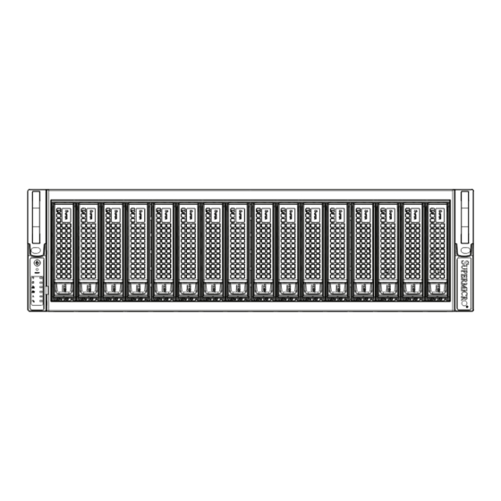
Summary of Contents for Supero SC936 Series
- Page 1 UPER ® SC936 CHASSIS SERIES SC936A-R900B SC936E1-R900B SC936E2-R900B USER’S MANUAL 1.0a...
- Page 2 SC936 Chassis Manual The information in this User’s Manual has been carefully reviewed and is believed to be accurate. The vendor assumes no responsibility for any inaccuracies that may be contained in this document, makes no commitment to update or to keep current the information in this manual, or to notify any person or organization of the updates.
- Page 3 Preface Preface About This Manual This manual is written for professional system integrators and PC technicians. It provides information for the installation and use of the SC936 chassis. Installation and maintenance should be performed by experienced technicians only. This Supermicro SC936 chassis features a unique and highly-optimized design with Intel/AMD based DP, UP processors The chassis is equipped with a 900W high efficiency power supply.
- Page 4 SC936 Chassis Manual Manual Organization Chapter 1 Introduction The first chapter provides a checklist of the main components included with this chassis and describes the main features of the SC936 chassis. This chapter also includes contact information. Chapter 2 System Safety This chapter lists warnings, precautions, and system safety.
-
Page 5: Table Of Contents
Preface Table of Contents Chapter 1 Introduction Overview ......................1-1 Shipping List ....................1-1 Where to get Replacement Components ............1-2 Contacting Supermicro ..................1-3 Returning Merchandise for Service ..............1-4 Chapter 2 System Safety Overview ......................2-1 Warnings and Precautions ................2-1 Preparing for Setup .................. - Page 6 SC936 Chassis Manual Rack Mounting Instructions ................5-4 Identifying the Sections of the Rack Rails ............5-4 Inner Rail Extension ..................5-4 Appendix A Cables, Screws, and Other Accessories Appendix B Power Supply Specifications Appendix C SAS-936A Backplane Specifications Appendix D SAS-936EL Backplane Specifications...
-
Page 7: Chapter 1 Introduction
Chapter 1: Introduction Chapter 1 Introduction Overview Supermicro’s SC936 3U chassis features a unique and highly-optimized design. The chassis is equipped with high-efficiency redundant power supplies. High-per- formance fans provide ample optimized cooling for FB-DIMM memory modules and four hot-swappable drive bays offer maximum storage capacity. Shipping List Part Numbers Please visit the following link for the latest shipping lists and part numbers for your... -
Page 8: Where To Get Replacement Components
SC936 Chassis Manual Where to get Replacement Components Though not frequently, you may need replacement parts for your system. To en- sure the highest level of professional service and technical support, we strongly recommend purchasing exclusively from our Supermicro Authorized Distributors / System Integrators / Resellers. -
Page 9: Contacting Supermicro
Chapter 1 Introduction Contacting Supermicro Headquarters Address: Super Micro Computer, Inc. 980 Rock Ave. San Jose, CA 95131 U.S.A. Tel: +1 (408) 503-8000 Fax: +1 (408) 503-8008 Email: marketing@supermicro.com (General Information) support@supermicro.com (Technical Support) www.supermicro.com Site: Europe Address: Super Micro Computer B.V. Het Sterrenbeeld 28, 5215 ML 's-Hertogenbosch, The Netherlands Tel:... -
Page 10: Returning Merchandise For Service
SC936 Chassis Manual Returning Merchandise for Service A receipt or copy of your invoice marked with the date of purchase is required be- fore any warranty service will be rendered. You can obtain service by calling your vendor for a Returned Merchandise Authorization (RMA) number. When returning to the manufacturer, the RMA number should be prominently displayed on the outside of the shipping carton, and mailed prepaid or hand-carried. -
Page 11: Chapter 2 System Safety
Chapter 2 System Safety Chapter 2 System Safety Overview This chapter provides a quick setup checklist to get your chassis up and running. Following the steps in order given should enable you to have your chassis setup and operational within a minimal amount of time. This quick set up assumes that you are an experienced technician, famailiar with common concepts and terminology. - Page 12 SC936 Chassis Manual • Do not work alone when working with high voltage components. • Power should always be disconnected from the system when removing or in- stalling main system components, such as the motherboard, memory modules, DVD-ROM and floppy drives (not necessary for hot swappable drives). When disconnecting power, you should first power down the system with the operating system and then unplug the power cords from all the power supply modules in the system.
-
Page 13: General Safety Precautions
Chapter 2 System Safety General Safety Precautions • Keep the area around the chassis clean and free of clutter. • Place the chassis top cover and any system components that have been re- moved away from the system or on a table so that they won’t accidentally be stepped on. - Page 14 SC936 Chassis Manual • Handle a board by its edges only; do not touch its components, peripheral chips, memory modules or contacts. • When handling chips or modules, avoid touching their pins. • Put the motherboard and peripherals back into their antistatic bags when not in use.
-
Page 15: Chapter 3 System Interface
Chapter 3 System Interface Chapter 3 System Interface Overview There are several LEDs on the control panel as well as others on the drive carriers to keep you constantly informed of the overall status of the system as well as the activity and health of specific components. -
Page 16: Control Panel Buttons
SC936 Chassis Manual Control Panel Buttons There are two push-buttons located on the front of the chassis. These are (in order from left to right) a reset button and a power on/off button. • Power: The main power switch is used to apply or remove power from the power supply to the server system. - Page 17 Chapter 3 System Interface • NIC1: Indicates network activity on GLAN1 when flashing. • Overheat/Fan Fail: When this LED flashes it indicates a fan failure. When continuously on (not flashing) it indicates an overheat condition, which may be caused by cables obstructing the airflow in the system or the ambient room temperature being too warm.
- Page 18 SC936 Chassis Manual Notes...
-
Page 19: Chapter 4 Chassis Setup And Maintenance
Chapter 4 Chassis Setup and Maintenance Chapter 4 Chassis Setup and Maintenance Overview This chapter covers the steps required to install components and perform mainte- nance on the chassis. The only tool you will need to install components and perform maintenance is a Phillips screwdriver. -
Page 20: Removing The Chassis Cover
SC936 Chassis Manual Removing the Chassis Cover Release Tab Figure 4-1: Removing the Chassis Cover Removing the Chassis Cover: Press the release tabs to remove the cover from the locked position. Press both tabs at the same time. Once the top cover is released from the locked position, slide the cover back toward the rear of the chassis. - Page 21 Chapter 4 Chassis Setup and Maintenance Release Button Removing Hard Drive Trays from the Chassis Press the release button on the drive tray. This extends the drive tray handle. Use the handle to pull the drive out of the chassis. The drives are mounted in drive trays to simplify their installation and removal from the chassis.
- Page 22 SC936 Chassis Manual Slide the hard drive into the tray with the printed circuit board side facing down. Carefully align the mounting holes in both the drive tray and the hard drive. Secure the hard drive to the tray using the screws provided. Replace the drive tray into the chassis.
-
Page 23: Installing The Motherboard
Chapter 4 Chassis Setup and Maintenance Installing the Motherboard I/O Shield The I/O shield holds the motherboard ports in place. Install the I/O shield before you install the motherboard. Installing the I/O Shield: Review the documentation that came with your motherboard. Become familiar with component placement, requirements, and precautions. -
Page 24: Add-On Card/Expansion Slot Setup
SC936 Chassis Manual Installing the Motherboard: Review the documentation that came with your motherboard. Become familiar with component placement, requirements, precautions, and cable connec- tions. Open the chassis cover. As required by your motherboard, install standoffs in any areas that do not have a permanent standoff. -
Page 25: Installing The Air Shroud
Chapter 4 Chassis Setup and Maintenance Installing the Air Shroud Air Shroud Extension Air Shroud Rear Fans Figure 4-4: Air Shroud for SC936 Chassis Air shrouds concentrate airflow to maximize fan efficiency. The SC936 chassis air shroud is designed to fit snuggly within the chassis, and does not require tools for setup. -
Page 26: System Fans
SC936 Chassis Manual The air shroud includes perforations on the bottom. These perforations can be removed if motherboard components interfere with the air shroud placement. Do not remove more perforations than necessary. Install the rear fans by sliding each fan into the fan housing on the chassis. Checking the Server's Air Flow Make sure there are no objects to obstruct airflow in and out of the server. - Page 27 Chapter 4 Chassis Setup and Maintenance Figure 4-5: Placing the System Fan Replacing a System Fan 1. If necessary, open the chassis while the power is running to determine which fan has failed. (Never run the server for an extended period of time with the chassis open.) 2.
-
Page 28: Power Supply
SC936 Chassis Manual Power Supply The SC936 Chassis has an auto-switching power supply. This enables it to automati- cally sense and operate at a 100v to 240v input voltage. An amber light illuminates on the power supply when the power is off. An illuminated green light indicates that the power supply is operating. - Page 29 Chapter 4 Chassis Setup and Maintenance Figure 4-7: Changing the Power Distributor Server chassis that are 2U or higher require a power distributor. The power distribu- tor provides failover and power supply redundancy. In the unlikely event you must change the power distributor, do following: Changing the Power Distributor Power down the server and remove the plug from the wall socket or power strip.
- Page 30 SC936 Chassis Manual Notes 4-12...
-
Page 31: Chapter 5 Rack Installation
Chapter 5 Rack Installation Chapter 5 Rack Installation Overview This chapter provides a quick setup checklist to get your chassis up and running. Following these steps in the order given should enable you to have the system operational within a minimum amount of time. Unpacking the System You should inspect the box the chassis was shipped in and note if it was damaged in any way. -
Page 32: Rack Precautions
SC936 Chassis Manual Warnings and Precautions! Rack Precautions • Ensure that the leveling jacks on the bottom of the rack are fully extended to the floor with the full weight of the rack resting on them. • In single rack installation, stabilizers should be attached to the rack. •... -
Page 33: Rack Mounting Considerations
Chapter 5 Rack Installation Rack Mounting Considerations Ambient Operating Temperature If installed in a closed or multi-unit rack assembly, the ambient operating tempera- ture of the rack environment may be greater than the ambient temperature of the room. Therefore, consideration should be given to installing the equipment in an environment compatible with the manufacturer’s maximum rated ambient tempera- ture (Tmra). - Page 34 SC936 Chassis Manual Rack Mounting Instructions This section provides information on installing the SC936 chassis into a rack unit with the rails provided. There are a variety of rack units on the market, which may mean the assembly procedure will differ slightly. You should also refer to the instal- lation instructions that came with the rack unit you are using.
- Page 35 Chapter 5 Rack Installation Installing the Outer Rails to the Rack Attach the short bracket to the outside of the long bracket. You must align the pins with the slides. Also, both bracket ends must face the same direction. Adjust both the short and long brackets to the proper distance so that the rail fits snugly into the rack.
- Page 36 SC936 Chassis Manual Figure 5-3: Installing the Outer Rails to the Server Rack Figure 5-4: Installing the Rack Rails...
- Page 37 Appendix A Chassis Cables Appendix A Cables, Screws, and Other Accessories A-1 Overview This appendix lists supported cables for your chassis system. It only includes the most commonly used components and configurations. For more compatible cables, refer to the manufacturer of the motherboard you are using and our Web site at: www.supermicro.com.
- Page 38 SC936 Chassis Manual A-3 Compatible Cables These cables are compatible with the SC936 Chassis. Alternate SAS Cables Some compatible motherboards have different connectors. If your motherboard has only one SAS connector that the SAS cables must share, use one of the following cables.
- Page 39 Appendix A Chassis Cables Front Panel to the Motherboard The SC936 chassis includes a cable to connect the chassis front panel to the motherboard. If your motherboard uses a different connector, use the following list to find a compatible cable. Front Panel to Motherboard Cable (Ribbon Cable) Number of Pins Number of Pins...
- Page 40 SC936 Chassis Manual A-4 Chassis Screws The accessory box includes all the screws needed to setup your chassis. This section lists and describes the most common screws used. Your chassis may not require all the parts listed. HARD DRIVE Flat head Pan head 6-32 x 5 mm 6-32 x 5 mm...
- Page 41 Appendix B Power Supply Specifications Appendix B Power Supply Specifications This appendix lists power supply specifications for your chassis system. SC936A-R900B, SC936E1-R900B and SC936E2-R900B Redundant 900W MFR Part # PWS-902-1R 100 - 240V AC Voltage 50 - 60Hz 13 - 4 Amp +5V 30 Amp +5V standby 4 Amp +12V 75 Amp...
- Page 42 SC936 Chassis Manual Notes...
- Page 43 Safety Information and Technical Specifications Appendix C SAS-936A Backplane Specifications To avoid personal injury and property damage, carefully follow all the safety steps listed below when accessing your system or handling the components. C-1 ESD Safety Guidelines Electric Static Discharge (ESD) can damage electronic components. To prevent damage to your system, it is important to handle it very carefully.
- Page 44 SC936 Chassis Manual C-3 A Note to Users • All images and layouts shown in this user's guide are based upon the latest PCB Revision available at the time of publishing. The card you have received may or may not look exactly the same as the graphics shown in this manual. Jumper Settings and Pin Definitions C-4 Front Connectors and Jumpers SAS936A...
- Page 45 Safety Information and Technical Specifications C-5 Front Connector and Pin Definitions 1. MG9072 Chip The MG9072 is an enclosure management chip that supports the SES-2 controller and SES-2 protocols. 2. Upgrade Connectors The upgrade connectors are designated JP69, and JP78 are used for manufacturer's diagnos- tic purposes only.
- Page 46 SC936 Chassis Manual 6. Backplane Main Power Connectors Backplane Main Power The 4-pin connectors, designated JP10, 4-Pin Connector (JP10, JP13, JP46, JP13, JP46 and JP48, provide power to the and JP48) backplane. See the table on the right for pin Pin# Definition definitions.
- Page 47 Safety Information and Technical Specifications C-6 Front Jumper Locations and Pin Definitions Explanation of Jumpers Connector Pins To modify the operation of the backplane, jumpers can be used to choose between optional settings. Jumpers create shorts between two pins to change the function Jumper of the connector.
- Page 48 SC936 Chassis Manual SAS936A REV: SEC_I2C JP99 JP97 JP99 JP62 +12V +12V +12V +12V FAN1 FAN3 FAN2 PWR3 PWR2 PWR1 PWR0 JP63 JP61 Figure C-3: Fan Jumper Locations Fan Jumper Settings This backplane can use up to four fans. To utilize each fan, you must configure both jumpers as instructed below.
- Page 49 Safety Information and Technical Specifications C and SGPIO Modes and Jumper Settings This backplane can utilize I C or SGPIO. SGPIO is the default mode and can be used without making changes to your jumper. The following information details which jumper must be configured to use SGPIO mode or restore your backplane to I C mode.
- Page 50 SC936 Chassis Manual Front LED Indicators SAS936A REV: SEC_I2C +12V +12V +12V +12V FAN1 FAN3 FAN2 PWR3 PWR2 PWR1 PWR0 Front Panel LEDs STATE SPECIFICATION Failure in Fan #1. Failure in Fan #2. Failure in Fan #3. Alarm #1: Overheat/Drive Failure/Fan Fail- ure in Channels 0-7.
- Page 51 Safety Information and Technical Specifications C-7 Rear Connectors and LED Indicators FAIL0 ACT0 FAIL1 ACT1 FAIL2 ACT2 FAIL3 ACT3 FAIL4 ACT4 FAIL5 ACT5 FAIL6 ACT6 FAIL7 ACT7 FAIL8 ACT8 FAIL9 ACT9 FAIL10 ACT10 FAIL11 ACT11 FAIL12 ACT12 FAIL13 ACT13 FAIL14 ACT14 FAIL15 ACT15...
- Page 52 SC936 Chassis Manual Rear LED Indicators Rear LED Hard Drive Activity Failure LED SAS #0 SAS #1 SAS #2 SAS #3 SAS #4 SAS #5 SAS #6 SAS #7 SAS #8 SAS #9 SAS #10 SAS #11 SAS #12 SAS #13 SAS #14 SAS #15 C-10...
Need help?
Do you have a question about the SC936 Series and is the answer not in the manual?
Questions and answers