
Related Manuals for Supero Supero SC808T-1200W


Summary of Contents for Supero Supero SC808T-1200W
- Page 1 UPER ® SC808 Chassis Series SC808T-1200W SC808T-980V SC808T-980B SC808T-780B SC808LT-780B USER’S MANUAL 1.0b...
- Page 2 Please Note: For the most up-to-date version of this manual, please see our web site at www.supermicro.com. Super Micro Computer, Inc. ("Supermicro") reserves the right to make changes to the product described in this manual at any time and without notice. This product, including software, if any, and documentation may not, in whole or in part, be copied, photocopied, reproduced, translated or reduced to any medium or machine without prior written consent.
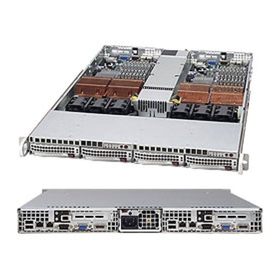
- Page 3 SC808 1U chassis. Installa- tion and maintenance should be performed by experienced technicians only. Supermicro's SC808 1U chassis features a unique and highly-optimized design for 1U Twin™ servers. The layout and chassis design provides 2 nodes in 1U and up to 84 nodes in a 42U standard rack, which significantly reduces IT space costs.
-
Page 4: Manual Organization
SC808 Chassis Manual Manual Organization Chapter 1: Introduction The first chapter provides a checklist of the main components included with this chassis, and describes the main features of the SC808 chassis. This chapter also includes contact information. Chapter 2: System Safety This chapter lists warnings, precautions, and system safety. - Page 5 Preface Compatible Backplanes This section lists compatible cables, power supply specifications, and compatible backplanes. Not all compatible backplanes are listed. Refer to our Web site for the latest compatible backplane information. Appendix A: Chassis Cables Appendix B: Power Supply Specifications Appendix C: SAS-808 Backplane Specifications...
-
Page 6: Table Of Contents
Manual Organization ..................iv Chapter 1 Introduction Overview ......................1-1 Shipping List ....................1-1 Part Numbers ....................1-1 Contacting Supermicro ..................1-2 Returning Merchandise for Service..............1-3 Chapter 2 System Safety Overview ......................2-1 Warnings and Precautions ................2-1 Preparing for Setup ..................2-1 Electrical Safety Precautions ................ - Page 7 Preface System Fans ....................5-12 Power Supply ....................5-14 Power Supply Replacement ................5-14 Chapter 6 Rack Installation Overview ......................6-1 Unpacking the System ..................6-1 Preparing for Setup ..................6-1 Choosing a Setup Location ................6-1 Rack Precautions .................... 6-2 General Server Precautions ................
- Page 8 SC808 Chassis Manual Notes viii...
-
Page 9: Chapter 1 Introduction
Chapter 1 Introduction Overview Supermicro’s SC808 1U chassis features a unique and highly-optimized design. The chassis is equipped with a high-efficiency power supply. High-performance fans pro- vide ample optimized cooling for FB-DIMM memory modules and 4 hot-swappable drive bays offer maximum storage capacity in a 1U form factor. -
Page 10: Contacting Supermicro
Super Micro Computer, Inc. 980 Rock Ave. San Jose, CA 95131 U.S.A. Tel: +1 (408) 503-8000 Fax: +1 (408) 503-8008 Email: marketing@supermicro.com (General Information) support@supermicro.com (Technical Support) Web Site: www.supermicro.com Europe Address: Super Micro Computer B.V. Het Sterrenbeeld 28, 5215 ML... -
Page 11: Returning Merchandise For Service
For faster service, RMA authorizations may be requested online (http://www. supermicro.com/support/rma/). Whenever possible, repack the chassis in the original Supermicro carton, using the original packaging material. If these are no longer available, be sure to pack the chassis securely, using packaging material to surround the chassis so that it does not shift within the carton and become damaged during shipping. - Page 12 SC808 Chassis Manual Notes...
-
Page 13: Chapter 2 System Safety
Chapter 2: System Safety Chapter 2 System Safety Overview This chapter provides a quick setup checklist to get your chassis up and running. Following the steps in order given should enable you to have your chassis set up and operational within a minimal amount of time. This quick setup assumes that you are an experienced technician, famailiar with common concepts and terminology. - Page 14 SC808 Chassis Manual • Power should always be disconnected from the system when removing or in- stalling main system components, such as the serverboard, memory modules and the DVD-ROM and floppy drives (not necessary for hot swappable drives). When disconnecting power, you should first power down the system with the operating system and then unplug the power cords from all the power supply modules in the system.
-
Page 15: General Safety Precautions
Chapter 2: System Safety General Safety Precautions • Keep the area around the chassis clean and free of clutter. • Place the chassis top cover and any system components that have been re- moved away from the system or on a table so that they won’t accidentally be stepped on. - Page 16 SC808 Chassis Manual • Handle a board by its edges only; do not touch its components, peripheral chips, memory modules or contacts. • When handling chips or modules, avoid touching their pins. • Put the serverboard and peripherals back into their antistatic bags when not in use.
-
Page 17: Chapter 3 Chassis Components
Components Chassis The SC808 chassis includes four hard drive bays. Hard drives must be purchased separately. For the latest shipping lists, visit our Web site at: http://www.supermicro. com. Backplane Each SC808 chassis comes with a 1U backplane. For more information regarding compatible backplanes, view the appendices found at the end of this manual. -
Page 18: Where To Get Replacement Components
Supermicro Authorized Distributors / System Integrators / Resellers. A list of Supermicro Authorized Distributors / System Integrators /Reseller can be found at: http://www.supermicro.com. Click the Where... -
Page 19: Chapter 4 System Interface
Chapter 4: System Interface Chapter 4 System Interface Overview There are several LEDs on the control panel and drive carriers to keep you con- stantly informed of the overall status of the system. SC808 models include two front panels that control two semi-independent system. This chapter explains the meanings of all LED indicators and the appropriate re- sponse you may need to take. -
Page 20: Control Panel Buttons
SC808 Chassis Manual Control Panel Buttons There are two push-buttons located on the front of the chassis. These are (in order from left to right) a reset button and a power on/off button. • Reset: The reset button is used to reboot the system. •... -
Page 21: Drive Carrier Leds
Chapter 4: System Interface • NIC2: Indicates network activity on GLAN2 when flashing. • NIC1: Indicates network activity on GLAN1 when flashing. • HDD: Indicates IDE channel activity. SAS/SATA drive, and/or DVD-ROM drive activity when flashing. • Power: Indicates power is being supplied to the system's power supply units. This LED should normally be illuminated when the system is operating. -
Page 22: Scsi Drives
SC808 Chassis Manual nection to the SATA backplane enables this LED to blink on and off when that particular drive is being accessed. • Red: The red LED to indicate an SAS/SATA drive failure. If one of the SAS/SATA drives fail, you should be notified by your system management software. SCSI Drives This chassis does not support SCSI drives at this time. -
Page 23: Chapter 5 Chassis Setup And Maintenance
Chapter 5: Chassis Setup and Maintenance Chapter 5 Chassis Setup and Maintenance Overview This chapter covers the steps required to install components and perform mainte- nance on the chassis. The only tool you will need to install components and perform maintenance is a Phillips screwdriver. -
Page 24: Removing The Chassis Cover
SC808 Chassis Manual Removing the Chassis Cover Remove this Remove this screw screw Remove this screw Figure 5-1: Removing the Chassis Cover Removing the Chassis Cover Disconnect the chassis from any power source and remove all four screws. Gently push down on the chassis cover in the areas indicated in the illustra- tion. -
Page 25: Installing And Removing Hard Drives
Chapter 5: Chassis Setup and Maintenance Installing and Removing Hard Drives Figure 5-2: Removing Hard Drive Removing Hard Drive Carriers from the Chassis Press the release button on the drive carrier. This extends the drive handle. Use the handle to pull the drive out of the chassis. - Page 26 SC808 Chassis Manual Dummy Drive Drive Tray Figure 5-3: Chassis Drive Carrier The drives are mounted in drive carriers to simplify their installation and removal from the chassis. These carriers also help promote proper airflow in the drive bays. Warning: Except for short periods of time (swapping hard drives), do not operate the server with the carriers abscent.
- Page 27 Use the open handle to slide the drive carrier into the chassis. Close the drive carrier handle. Warning! Enterprise level hard disk drives are recommended for use in Supermicro chassis and servers. For information on recommended HDDs, visit the Supermicro Web site at http:// www.supermicro.com/products/nfo/files/storage/SAS-1-Com-...
-
Page 28: Installing The Motherboard
SC808 Chassis Manual Installing the Motherboard I/O Shields Figure 5-6: I/O Shield Placement I/O Shield The I/O shield holds the motherboard ports in place. The I/O shield does not require installation, however, the motherboard must match up with the I/O shield. Permanent and Optional Standoffs Standoffs prevent short circuits by securing space between the motherboard and the chassis surface. - Page 29 Chapter 5: Chassis Setup and Maintenance Remove these screws Figure 5-7: Expansion Card Bracket Installing the Motherboard Review the documentation that came with your motherboard. Become familiar with component placement, requirements, precautions, and cable connec- tions. Disconnect the chassis from any power source and open the chassis cover. Remove the expansion card brackets.
-
Page 30: Expansion Slot Setup
SC808 Chassis Manual Connect the cables between the motherboard, backplane, chassis, front panel, and power supply, as needed. Also, fans may be temporarily removed to allow access to the backplane ports. Replace the expansion card bracket and secure the bracket with a screw. Expansion Slot Setup SC808 chassis includes I/O slots for expansion cards. - Page 31 Chapter 5: Chassis Setup and Maintenance Expansion Card Bracket Screw Expansion Card Bracket Riser Card PCI Slot Cover Expansion Card Figure 5-9: I/O Shield Placement Connect the expansion card to the riser card and slide the expansion card "L" bracket in to the rear expansion card slot. Close the expansion card slot clip.
-
Page 32: Installing The Air Shrouds
SC808 Chassis Manual Installing the Air Shrouds Air Shrouds Air shrouds concentrate airflow to maximize fan efficiency. The SC808 chassis air shroud does not require screws to set up. The SC808 chassis requires two identi- cal air shrouds. Installing an Air Shroud Confirm that all six fans are in place and working properly Place the first air shroud into the chassis. -
Page 33: Checking The Air Flow
Chapter 5: Chassis Setup and Maintenance Checking the Air Flow Checking Air Flow Make sure there are no objects obstructing airflow in and out of the server. In addition, if you are using a front bezel, make sure the bezel's filter is replaced periodically. -
Page 34: System Fans
SC808 Chassis Manual System Fans Six fans provide cooling for the chassis. These fans circulate air through the chassis as a means of lowering the chassis internal temperature. The SC808 system fans are hot-swappable. There is no need to power-down the system when switching fans. - Page 35 Chapter 5: Chassis Setup and Maintenance Figure 5-11: System Fan Placement 5-13...
-
Page 36: Power Supply
The SC808 chassis utilizes one power supply. In the unlikely event that the power supply unit must be replaced, the system will shut down. Replacement units can be ordered directly from Supermicro (see contact information in the Preface). Release Tab... - Page 37 Chapter 5: Chassis Setup and Maintenance Changing the Power Supply Power down the chassis and unplug the AC power cord. Push the release tab (on the back of the power supply) as illustrated. Pull the power supply out using the handle provided. Push the new power supply module into the power bay until you hear a click.
- Page 38 SC808 Chassis Manual Notes 5-16...
-
Page 39: Chapter 6 Rack Installation
Chapter 6: Rack Installation Chapter 6 Rack Installation Overview This chapter provides a quick setup checklist to install the chassis into a rack. Fol- lowing the steps in the order given should enable you to have the system installed within a minimal amount of time. Unpacking the System You should inspect the box the chassis was shipped in and note if it was damaged in any way. -
Page 40: Rack Precautions
SC808 Chassis Manual Warnings and Precautions! Rack Precautions • Ensure that the leveling jacks on the bottom of the rack are fully extended to the floor with the full weight of the rack resting on them. • In single rack installation, stabilizers should be attached to the rack. •... -
Page 41: Rack Mounting Considerations
Chapter 6: Rack Installation Rack Mounting Considerations Ambient Operating Temperature If installed in a closed or multi-unit rack assembly, the ambient operating tempera- ture of the rack environment may be greater than the ambient temperature of the room. Therefore, consideration should be given to installing the equipment in an environment compatible with the manufacturer’s maximum rated ambient tempera- ture (Tmra). -
Page 42: Rack Mounting Instructions
SC808 Chassis Manual Rack Mounting Instructions This section provides information on installing the SC808 chassis into a rack unit with the rails provided. There are a variety of rack units on the market, which may mean the assembly procedure will differ slightly. You should also refer to the installation instructions that came with the rack unit you are using. -
Page 43: Installing The Inner Rail Extension
Chapter 6: Rack Installation Figure 6-2: Installing the Inner Rail Extension Installing the Inner Rail Extension The SC808 chassis includes a set of inner rails in two sections: Inner rails and inner rail extensions. The inner rails are preattached and do not interfere with normal use of the chassis if you decide not to use a server rack. - Page 44 SC808 Chassis Manual Secure to the Front of the Rack Secure to the Rear of the Rack Attach Outer Racks together Figure 6-3: Assembling the Outer Rails Installing the Outer Rails to the Rack Attach the short bracket to the outside of the long bracket. You must align the pins with the slides.
- Page 45 Chapter 6: Rack Installation Figure 6-4: Installing the Chassis into a Rack Installing the Chassis into a Rack Confirm that chassis includes the inner rails (A) and rail extensions (B). Also, confirm that the outer rails (C) are installed on the rack. Line chassis rails (A and B) with the front of the rack rails (C).
- Page 46 SC808 Chassis Manual Notes...
-
Page 47: Appendix A Cables, Screws, And Other Accessories
This appendix lists supported cables for your chassis system. It only includes the most commonly used components and configurations. For more compatible cables, refer to the manufacturer of the motherboard you are using and our Web site at: www.supermicro.com. A-2 Cables Included with SC808 Chassis (SAS/SATA) SC808LT-780B, SC808T-780B, SC808T-980B... -
Page 48: Extending Power Cables
(motherboard or other controller) to the backplane's SAS hard drive port. Extending Power Cables Although Supermicro chassis are designed with to be efficient and cost-effective, some compatible motherboards have power connectors located in different areas. To use these motherboards, you may have to extend the power cables to the mother boards. -
Page 49: Front Panel To The Motherboard
Appendix A: Cables, Screws and Other Accessories Front Panel to the Motherboard The SC808 chassis includes a cable to connect the chassis front panel to the motherboard. If your motherboard uses a different connector, use the following list to find a compatible cable. Front Panel to Motherboard Cable (Ribbon Cable) Number of Pins Number of Pins... - Page 50 SC808 Chassis Manual A-5 Chassis Screws The chassis and accessory box includes all of the screws needed to setup your chassis. This section includes descriptions of the most common screws used. Your chassis may not require all of the parts listed. HARD DRIVE Flat head Pan head...
-
Page 51: Appendix B Sc808 Power Supply Specifications
Appendix B: Power Supply Specifications Appendix B SC808 Power Supply Specifications This appendix lists power supply specifications for your chassis system. SC808LT-780B and SC808T-780B 780W MFR Part # PWS-781-1S 180 - 240V 50 - 60Hz Rated AC Voltage 5 - 3.5 Amp* *Power supply operates at 700W with a 100-140V input, and at 780W with a 180-240V input +5V standby 4 Amp... - Page 52 SC808 Chassis Manual SC808T-1200B 1200W MFR Part # PWS-1K21P-1R 100 - 140V 50 - 60Hz 7.5 - 11 Amp Rated AC Input 180 - 240V 50 - 60Hz 5 - 8 Amp *Power supply operates at 1200W with a 100-140V input and at 1200W with a 180-240V input +5V standby 4 Amp 74 Amp @ 100 - 140...
-
Page 53: Appendix C Sas-808 Backplane Specifications
Appendix C: SAS-808 Backplane Specifications Appendix C SAS-808 Backplane Specifications To avoid personal injury and property damage, carefully follow all the safety steps listed below when accessing your system or handling the components. C-1 ESD Safety Guidelines Electrostatic Discharge (ESD) can damage electronic com ponents. To prevent dam- age to your system, it is important to handle it very carefully. - Page 54 This manual reflects SAS-808 Revision 1.00, the most current release available at the time of publication. Always refer to the Supermicro Web site at www.supermicro. com for the latest updates, compatible parts and supported configurations.
- Page 55 Appendix C: SAS-808 Backplane Specifications C-5 Front Connectors J P13 J P10 SAS808 REV 1. 0 +12V +12V Figure C-1: Front Connectors Power connectors (4-pin) JP10 and JP13 SAS Port #0 J5 SAS Port #1 J6 SAS Port #2 J7 SAS Port #3 J8...
- Page 56 SC808 Chassis Manual C-6 Front Connectors and Pin Definitions 1. Backplane Main Power Connectors Backplane Main Power The 4-pin connectors, designated JP10 and 4-Pin Connector JP13, provide power to the backplane. See Pin# Definition the table on the right for pin definitions. +12V 2 and 3 Ground...
-
Page 57: Explanation Of Jumpers
Appendix C: SAS-808 Backplane Specifications C-7 Front Jumper Locations and Pin Definitions J P13 J P10 SAS808 REV 1. 0 +12V +12V JP18 J P13 JP25 +12V Figure C-2: Front Jumpers Explanation of Jumpers To modify the operation of the backplane, Connector Pins jumpers can be used to choose between... -
Page 58: Front Led Indicators
SC808 Chassis Manual Front LED Indicators J P13 J P10 SAS808 REV 1. 0 +12V +12V J P13 +12V Figure C-3: Front LEDs Front LED Indicators State Specification Overheat LED Indicator... -
Page 59: Rear Connectors And Led Indicators
J P13 J P10 SAS808 REV 1. 0 Appendix C: SAS-808 Backplane Specifications +12V +12V Rear Connectors and LED Indicators SAS #0 SAS #3 SAS #2 SAS #1 Figure C-4: Rear Connectors and LEDs Rear SAS/SATA Connectors Rear Connector SAS Drive Connector Number Number... - Page 60 SC808 Chassis Manual Disclaimer (cont.) The products sold by Supermicro are not intended for and will not be used in life sup- port systems, medical equipment, nuclear facilities or systems, aircraft, aircraft devices, aircraft/emergency communication devices or other critical systems whose failure to per- form be reasonably expected to result in significant injury or loss of life or catastrophic property damage.
Need help?
Do you have a question about the Supero SC808T-1200W and is the answer not in the manual?
Questions and answers