
Related Manuals for Supero Supero SC512-200B


Summary of Contents for Supero Supero SC512-200B
- Page 1 UPER ® SC512 CHASSIS Series SC512-200B SC512C-260(B) SC512F-280(B) SC512F-520(B) SC512L-260(B) SC512F-520L(B) SC512L-260(B)-LCD SC512F-410(B) SC512L-200B SC512F-260(B) USER’S MANUAL 1.0a...
- Page 2 Manual Revision 1.0a Release Date: October 1, 2009 Unless you request and receive written permission from Super Micro Computer, Inc., you may not copy any part of this document. Information in this document is subject to change without notice. Other products and companies referred to herein are trademarks or registered trademarks of their respective companies or mark holders.
-
Page 3: About This Manual
Preface Preface About This Manual This manual is written for professional system integrators and PC technicians. It provides information for the installation and use of the SC512 1U chassis. Installa- tion and maintenance should be performed by experienced technicians only. Supermicro’s SC512 1U chassis features a unique and highly-optimized design for dual-core Xeon platforms. -
Page 4: Manual Organization
SC512 Chassis Manual Manual Organization Chapter 1: Introduction The first chapter provides a checklist of the main components included with this chassis and describes the main features. This chapter also includes contact infor- mation. Chapter 2: System Safety This chapter lists warnings, precautions, and system safety. You should thoroughly familiarize yourself with this chapter for a general overview of safety precautions that should be followed before installing and servicing this chassis. -
Page 5: Table Of Contents
Preface Table of Contents About This Manual ..................... iii Manual Organization ..................iv Chapter 1 Introduction Overview ......................1-1 Shipping List ....................1-1 Part Numbers ....................1-1 Chassis Features .................... 1-2 I/O Expansion slots ..................1-2 Peripheral Drives ..................... 1-2 Dual Hard Drives ..................... 1-2 Contacting Supermicro .................. - Page 6 SC512 Chassis Manual Chapter 4 System Interface Overview ......................4-1 Control Panel Buttons ..................4-2 Control Panel LEDs ..................4-2 Chapter 5 Chassis Setup and Maintenance Overview ......................5-1 Installation Procedures ..................5-1 General Maintenance ..................5-1 Removing the Chassis Cover ................. 5-2 Installing Hard Drives ..................
- Page 7 Preface Installing the Inner Rail Extension ..............6-5 Installing the Outer Rails to the Rack ............. 6-6 Installing the Chassis into a Rack..............6-8 Mid-Mount Telco Rack..................6-9 Installing the Chassis into a Rack in Mid-Mount Position ......6-9 Appendix A Cables, Screws, and Other Accessories Appendix B Power Supply Specifications...
- Page 8 SC512 Chassis Manual Notes viii...
-
Page 9: Chapter 1 Introduction
Chapter 1: Introduction Chapter 1 Introduction Overview Supermicro’s SC512 1U chassis features a unique and highly-optimized design. The chassis is equipped with a high efficiency power supply in a small form factor for optimized space efficiency. Shipping List Part Numbers Please visit the following link for the latest shiping lists and part numbers for your par- ticular chassis model http://www.supermicro.com/products/chassis/1U/?chs=512 SC512 Chassis... -
Page 10: Chassis Features
SC512 Chassis Manual Chassis Features The SC512 1U high-performance chassis supports a wide range of features. See the Chassis Components section of this manual for a list of featues included in each of the SC512 models. The SC512 chassis supports a DP Xeon, Pentium D or UP P3/P4 processor. Please refer to the motherboard specifications pages on our web site for updates on supported processors. -
Page 11: Contacting Supermicro
Chapter 1 Introduction Contacting Supermicro Headquarters Address: Super Micro Computer, Inc. 980 Rock Ave. San Jose, CA 95131 U.S.A. Tel: +1 (408) 503-8000 Fax: +1 (408) 503-8008 Email: marketing@supermicro.com (General Information) support@supermicro.com (Technical Support) Web Site: www.supermicro.com Europe Address: Super Micro Computer B.V. -
Page 12: Returning Merchandise For Service
SC512 Chassis Manual Returning Merchandise for Service A receipt or copy of your invoice marked with the date of purchase is required be- fore any warranty service will be rendered. You can obtain service by calling your vendor for a Returned Merchandise Authorization (RMA) number. When returning to the manufacturer, the RMA number should be prominently displayed on the outside of the shipping carton, and mailed prepaid or hand-carried. -
Page 13: Chapter 2 System Safety
Chapter 2: System Safety Chapter 2 System Safety Overview This chapter provides a quick setup checklist to get your chassis up and running. Following the steps in order given should enable you to have your chassis setup and operational within a minimal amount of time. This quick setup assumes that you are an experienced technician, famailiar with common concepts and terminology. - Page 14 SC512F Chassis Manual • Do not work alone when working with high voltage components. • Power should always be disconnected from the system when removing or in- stalling main system components, such as the serverboard, memory modules and the DVD-ROM and floppy drives (not necessary for hot swappable drives). When disconnecting power, you should first power down the system with the operating system and then unplug the power cords from all the power supply modules in the system.
-
Page 15: General Safety Precautions
Chapter 2: System Safety General Safety Precautions • Keep the area around the chassis clean and free of clutter. • Place the chassis top cover and any system components that have been re- moved away from the system or on a table so that they won’t accidentally be stepped on. - Page 16 SC512F Chassis Manual • Do not let components or PCBs come into contact with your clothing, which may retain a charge even if you are wearing a wrist strap. • Handle a board by its edges only; do not touch its components, peripheral chips, memory modules or contacts.
-
Page 17: Chapter 3 Chassis Components
Chapter 3: Chassis Components Chapter 3 Chassis Components Overview This chapter describes the most common components included with your chassis. Some components listed may not be included or compatible with your particular chassis model. For more information, see the installation instructions detailed later in this manual. -
Page 18: Power Supply
SC512 Chassis Manual Power Supply Each SC512 chassis model includes a high-efficiency power supply rated at 200, 260, 280, 410 or 580 Watts. In the unlikely event your power supply fails, replace- ment is simple and can be done without tools. Air Shroud Air shrouds are shields, usually plastic, that funnel air directly to where it is needed. - Page 19 Chapter 3: Chassis Components Air blower unit included in chassis models SC512, SC512C and SC512L Figure 3-1: Blower-Cooled Chassis Model System fans included in chassis model SC512F Figure 3-2: Fan-Cooled Chassis Model...
-
Page 20: Model Sc512
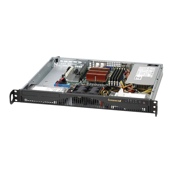
SC512 Chassis Manual Model SC512 Includes a slot with a dummy cover plate where an optional CD-ROM drive may be installed, and a 200 Watt power supply. The SC512 model chassis is cooled with an internal blower unit. Dummy Cover Plate for Optional CD-ROM Drive Figure 3-3: Chassis Model SC512... -
Page 21: Model Sc512F
Chapter 3: Chassis Components Model SC512F The SC512F models may include a DVD-ROM or CD-ROM drive, USB ports and a 260, 280, 410 or 520 Watt power supply. The SC512F-520L model can support a second optional hard disk drive. The SC512F-200 and SC512F-260 have a narrow chassis design, yet mount in a standard rack by utilizing special mounting rails. - Page 22 SC512 Chassis Manual DVD-ROM Drive USB Ports Figure 3-7: Chassis Model SC512F-410 Standard Chassis, System Fans, DVD-ROM, USB Ports, 520W Power Supply SC512F-410 Chassis Blower/Fan DVD/CD Floppy Power Supply Standard 1x DVD 1x 3.5" 520 Watt DVD-ROM Drive USB Ports Figure 3-8: Chassis Model SC512F-520 Standard Chassis, System Fans, DVD-ROM, USB Ports, 520W Power Supply SC512F-520...
-
Page 23: Model Sc512L
Chapter 3: Chassis Components Model SC512L The SC512L models include two 3.5" hard disk drives and a 200 or 260 Watt power supply. The SC512L model chassis is cooled with an internal blower unit. Figure 3-10: Chassis Model SC512L SC512L Chassis Blower/Fan DVD/CD... - Page 24 SC512 Chassis Manual Notes...
-
Page 25: Chapter 4 System Interface
Chapter 4: System Interface Chapter 4 System Interface Overview There are several LEDs on the control panel and on the drive carriers to keep you constantly informed of the overall status of the system, as well as the activity and health of specific components. -
Page 26: Control Panel Buttons
SC512 Chassis Manual Control Panel Buttons There are two push-buttons located on the front of the chassis. These are a reset button and a power on/off button. Reset: The reset button is used to reboot the system. Power: The main power switch is used to apply or remove power from the power supply to the server system. - Page 27 Chapter 4: System Interface NIC2: Indicates network activity on GLAN2 when flashing. NIC1: Indicates network activity on GLAN1 when flashing. HDD: Indicates IDE channel activity. SAS/SATA drive, SCSI drive, and/or DVD-ROM drive activity when flashing. Power: Indicates power is being supplied to the system's power supply units. This LED should normally be illuminated when the system is operating.
- Page 28 SC512 Chassis Manual Notes...
-
Page 29: Chapter 5 Chassis Setup And Maintenance
Chapter 5: Chassis Setup and Maintenance Chapter 5 Chassis Setup and Maintenance Overview This chapter covers the steps required to install components and perform mainte- nance on the chassis. The only tool you will need to install components and perform maintenance is a Phillips head and a flathead screwdriver. -
Page 30: Removing The Chassis Cover
SC512 Chassis Manual Removing the Chassis Cover Remove these screws Remove these screws HARD DRIVE Flat head Remove this screw 6-32 x 5 mm [0.197] PPY DRIVE Figure 5-1: Removing the Chassis Cover Round head Round head Removing the Chassis Cover 2.6 x 5 mm 3 x 5 mm [0.197]... -
Page 31: Installing Hard Drives
Chapter 5: Chassis Setup and Maintenance Installing Hard Drives Remove these screws HARD DRIVE Flat head 6-32 x 5 mm [0.197] OPPY DRIVE Round head Round head DVD-ROM/CD-ROM 2.6 x 5 mm 3 x 5 mm Drive [0.197] [0.197] und head Flat head x 4 mm M5 x 12 mm [0.472]... - Page 32 SC512 Chassis Manual HARD DRIVE Hard Drive Flat head Pan head 6-32 x 5 mm 6-32 x 5 mm [0.197] [0.197] DVD-ROM CD-ROM FLOPPY DRIVE Flat head Round head Pan head Round head 6-32 x 5 mm 2.6 x 5 mm 3 x 5 mm 6-32 x 5 mm [0.197]...
-
Page 33: Installing The Motherboard
Chapter 5: Chassis Setup and Maintenance Installing the Motherboard HARD DRIVE Flat head Pan head 6-32 x 5 mm 6-32 x 5 mm [0.197] [0.197] DVD-ROM CD-ROM FLOPPY DRIVE Figure 5-5: The SC512 Backplate (I/O Shield) Important Motherboard Installation Information Before installing the motherboard, be aware of the following: Flat head Round head... -
Page 34: Standoffs
HARD DRIVE SC512 Chassis Manual Standoffs Flat head Standoffs prevent short circuits by securing space between the motherboard and 6-32 x 5 mm the chassis surface. The SC512 chassis includes permanent standoffs in locations [0.197] used by most motherboards. These standoffs accept the rounded Phillips head FLOPPY DRIVE screws included in the SC512 accessories packaging. -
Page 35: Installing The Dvd Or Cd-Rom Drive
Chapter 5: Chassis Setup and Maintenance Installing the DVD or CD-ROM Drive HARD DRIVE Replace these screws Flat head 6-32 x 5 mm [0.197] OPPY DRIVE Round head Round head 2.6 x 5 mm 3 x 5 mm [0.197] [0.197] DVD-ROM/CD-ROM Drive d head... -
Page 36: Add-On Card/Expansion Slot Setup
SC512 Chassis Manual Add-on Card/Expansion Slot Setup SC512 chassis includes a slot for one full height/full length add-on card and a riser card. The riser card allows the add-on to fit within the small 1U form. The add-on card slot does not require a screw to hold the card in place. Add-on Card Slot Latch Add-on Card Slot Shield... -
Page 37: Installing The Air Shroud
Chapter 5: Chassis Setup and Maintenance Installing the Air Shroud The air shroud helps cool the chassis by directing heated air through the rear of the chassis. When installing the air fan, be aware of the following: • The air shroud is designed to fit within the chassis. The sides of the air shroud should remain straight in relation to the top. -
Page 38: Installation Complete
SC512 Chassis Manual Checking the Airflow in the Chassis 1. Make sure there are no objects to obstruct airflow in and out of the server. 2. Do not operate the server without drives or drive trays in the drive bays. Use only recommended server parts. -
Page 39: System Fans
Chapter 5: Chassis Setup and Maintenance System Fans Three heavy duty fans provide cooling for the chassis. These fans circulate air through the chassis as a means of lowering the chassis internal temperature. The SC512F-280 chassis accepts two fans instead of three. System Fan Tray Fan Tray Support Pin Rubber Grommet... -
Page 40: System Fan Tray Replacement
SC512 Chassis Manual System Fan Tray Replacement Installing the System Fan Tray Power down the system. Disconnect each fan from the motherboard. Lift the system fan tray and fans from the chassis. Retain the rubber mount- ings that encircle the tray rivets. Place the fans into the new system fan tray. -
Page 41: Power Supply
Chapter 5: Chassis Setup and Maintenance Power Supply Depending on your chassis model the SC512 chassis has a 200, 269, 280, 410 or 520 Watt power supply. This power supply is auto-switching capable. This enables it to automatically sense and operate at a 100v to 240v input voltage. An amber light will be illuminated on the power supply when the power is off. - Page 42 SC512 Chassis Manual Remove these screws HARD DRIVE Power Supply Pan Head Flat head 6-32 x 5mm Pan head [0.197] 6-32 x 5 mm 6-32 x 5 mm [0.197] Remove this screw [0.197] Figure 5-12: Removing the Power Supply DVD-ROM CD-ROM FLOPPY DRIVE Replacing the Power Supply Disconnect the power cord from the from the chassis to ensure that the unit is not accidentally plugged in.
-
Page 43: Replacing The Chassis Led Panel
Chapter 5: Chassis Setup and Maintenance Figure 5-13: Replacing the LED Panel Replacing the Chassis LED Panel In the unlikely event that the chassis LED and buttons fail, you can replace the panel. Replacement parts can be ordered from Super Micro or an authorized reseller. Replacing the Chassis LED Panel Power down and unplug the system. - Page 44 SC512 Chassis Manual Notes 5-16...
-
Page 45: Chapter 6 Rack Installation
Chapter 6: Rack Installation Chapter 6 Rack Installation Overview This chapter provides a quick setup checklist to get your chassis up and running. Following these steps in the order given should enable you to have the system operational within a minimum amount of time. Unpacking the System You should inspect the box the chassis was shipped in and note if it was damaged in any way. -
Page 46: Rack Precautions
SC512 Chassis Manual Warnings and Precautions! Rack Precautions • Ensure that the leveling jacks on the bottom of the rack are fully extended to the floor with the full weight of the rack resting on them. • In single rack installation, stabilizers should be attached to the rack. •... -
Page 47: Rack Mounting Considerations
Chapter 6: Rack Installation • Always keep the rack's front door and all panels and components on the servers closed when not servicing to maintain proper cooling. Rack Mounting Considerations Ambient Operating Temperature If installed in a closed or multi-unit rack assembly, the ambient operating tempera- ture of the rack environment may be greater than the ambient temperature of the room. -
Page 48: Rack Mounting Instructions
SC512 Chassis Manual Rack Mounting Instructions This section provides information on installing the SC512 chassis into a rack unit with the rails provided. There are a variety of rack units on the market, which may mean the assembly procedure will differ slightly. You should also refer to the installation instructions that came with the rack unit you are using. -
Page 49: Installing The Inner Rail Extension
Pan head Chapter 6: Rack Installation 6-32 x 5 mm [0.197] Installing the Inner Rail Extension DVD-ROM CD-ROM F The SC512F includes chassis ears that you must remove before installing the rails. Removing the Chassis Ears Locate and remove the three screws holding the chassis ear in place. Flat head Pan head 6-32 x 5 m... -
Page 50: Installing The Outer Rails To The Rack
[0.197] [0.197] SC512 Chassis Manual Flat head M5 x 12 mm [0.472] Washer for M5 Secure to the Rear of the Rack Thumb screw ) standoff Attach Outer Racks 6-32 x 5 mm [0.197] 6-32 together Secure to the Front of the Rack Figure 6-3: Assembling the Outer Rails Installing the Outer Rails to the Rack Installing the Outer Rails... - Page 51 Chapter 6: Rack Installation SCALE 0.380 Figure 6-4: Installing the Outer Rails to the Server Rack...
-
Page 52: Installing The Chassis Into A Rack
SC512 Chassis Manual Figure 6-5: Installing the Chassis into a Rack Installing the Chassis into a Rack Installing the Chassis Confirm that the inner rails are attached to the chassis. Also, confirm that the outer rails are installed on the rack. Align chassis rails with the front of the rack rails. -
Page 53: Mid-Mount Telco Rack
Chapter 6: Rack Installation HARD DRIVE Mid-Mount Telco Rack The SC512.supports Telco rack installation. The SC512 chassis compact design allows the chassis to be installed into a Telco rack without the use of rails. Flat head Pan head 6-32 x 5 mm 6-32 x 5 mm [0.197] [0.197]... - Page 54 [0.197] [0.197] SC512 Chassis Manual SCALE Flat head M5 x 12 mm [0.472] Washer for M5 Thumb screw ) standoff 6-32 x 5 mm [0.197] 6-32 SCALE Figure 6-7: Installing the Server into a Telco Rack Hold the chassis in the telco rack and screw the chassis to the rack using the three screw holes located in the chassis ears.
-
Page 55: Appendix A Cables, Screws, And Other Accessories
Appendix A: SC512 Chassis Cables Appendix A Cables, Screws, and Other Accessories A-1 Overview This appendix lists supported cables for your chassis system. It only includes the most commonly used components and configurations. For more compatible cables, refer to the manufacturer of the motherboard you are using and our Web site at: www.supermicro.com. - Page 56 SC512 Chassis Manual SC512F-410 Part # Type Length Description Seven pin SATA with two 90 degree CBL-0142L Cable 30 cm (~12") side connectors. Lead free. 16 pin to 16 pin FP Cable. Lead CBL-0156L Cable 40 cm Free. CBL-0084L Wire 9 cm DVD Cable.
- Page 57 Appendix A: SC512 Chassis Cables SC512L-260 Part # Type Length Description CBL-0049 Cable 9 cm 16 pin to 16 pin ribbon cable SC512L-260-LCD Part # Type Length Description CBL-0049 Cable 9 cm 16 pin to 16 pin ribbon cable Extending Power Cables Although Super Micro chassis are designed with to be efficient and cost-effective, some compatible motherboards have power connectors located in different areas.
- Page 58 SC512 Chassis Manual A-3 Routing the Chassis Cables In order for the SC512 chassis to perform safely and efficiently, it is important that the cables are routed correctly. Follow the instructions below and review both the cabling diagram and photograph to ensure that the cabling has been properly routed. Preparing the Chassis for Cable Routing Unplug the chassis from any power source.
- Page 59 Appendix A: SC512 Chassis Cables Routing Cable (1A) from Hard Drive (1B) Plug cable (1A) into the SATA port of hard drive (1B). Lift up the fan and run cable (1A) straight out from the port and under the fan. Route cable (1A) over the hard drive and through the left middle bracket.
- Page 60 SC512 Chassis Manual Checking the Cable Routing Check the cable routing by following out each cable in the previous steps and comparing them to the diagram in Figure A-1, and the photograph in Figure A-2. Figure A-2: Chassis Cable Routing...
- Page 61 Appendix A: SC512 Chassis Cables A-4 Chassis Screws The Chassis and accessory box include all the screws needed to setup your chassis. This section include descriptions of the most common screws used. Your chassis may not require all the parts listed. HARD DRIVE Flat head Pan head...
- Page 62 SC512 Chassis Manual Notes...
-
Page 63: Appendix B Power Supply Specifications
Appendix B: SC512F Power Supply Specifications Appendix B Power Supply Specifications This appendix lists power supply specifications for your chassis system. SC512 Chassis Model MFR Part # PWS-201-1H 100 - 240V Rated AC Voltage 50 - 60Hz 4-2 Amp Max +5V standby 2.0 Amp +12V 16.0 Amp +5V 8.0 Amp... - Page 64 SC512 Chassis Manual SC512F Chassis Models (See below for 410 model) 520/520L MFR Part # PWS-581-1R PWS-0055 PWS-281-1H 100 - 240V 100 - 240V 100 - 240V Rated AC Voltage 50 - 60Hz 60 - 50Hz 50 - 60Hz 7A-3A 4 Amp Max 5A MAX +5V standby 3 Amp...
- Page 65 Appendix B: SC512F Power Supply Specifications Notes...
- Page 66 SC512 Chassis Manual Disclaimer (cont.) The products sold by Supermicro are not intended for and will not be used in life sup- port systems, medical equipment, nuclear facilities or systems, aircraft, aircraft devices, aircraft/emergency communication devices or other critical systems whose failure to per- form be reasonably expected to result in significant injury or loss of life or catastrophic property damage.
Need help?
Do you have a question about the Supero SC512-200B and is the answer not in the manual?
Questions and answers