Table of Contents
Advertisement
Quick Links
Advertisement
Table of Contents

Subscribe to Our Youtube Channel
Related Manuals for National Instruments PXIe-7911


Summary of Contents for National Instruments PXIe-7911
- Page 1 PXIe-7911/7912/7915 Getting Started 2022-07-06...
-
Page 2: Table Of Contents
PXIe-7911/7912/7915 Front Panels..........8 Configuring the PXIe-7911/7912/7915 in MAX........12 FlexRIO Examples. -
Page 3: Getting Started Guide
Safety Guidelines Caution You can impair the protection provided by the PXIe-7911/7912/7915 if you use it in a manner not described in this document. Electromagnetic Compatibility Guidelines This product was tested and complies with the regulatory requirements and limits for electromagnetic compatibility (EMC) stated in the product specifications. -
Page 4: Flexrio Documentation And Resources
Contains product information and data flexrio. sheets for FlexRIO hardware. Table 1. FlexRIO Documentation and Resources Verifying the System Requirements To use the PXIe-7911/7912/7915, your system must meet certain requirements. For more information about minimum system requirements, recommended system, ni.com... -
Page 5: Unpacking The Kit
Store the device in the antistatic package when the device is not in use. PXIe-7911/7912/7915 Kit Contents The following items are included in the device kit: PXIe-7911/7912/7915 ■ Documentation: ■ PXIe-7911/7912/7915 Getting Started Guide (this document) ■ PXIe-7911/7912/7915 Safety, Environmental, and Regulatory ■ Information © National Instruments... -
Page 6: Preparing The Environment
PXIe-7911/7912/7915 Getting Started Preparing the Environment Ensure the environment in which you are using the PXIe-7911/7912/7915 meets the following specifications. Operating environment Ambient temperature 0 °C to 45 °C (Tested in accordance with IEC-60068-2-1 and range IEC-60068-2-2. Meets MIL-PRF-28800FClass 3 low temperature limit and MIL-PRF-28800FClass 4 high temperature limit.) -
Page 7: Installing The Pxie-7911/7912/7915
FlexRIO Support. Documentation for FlexRIO Support is available at ni.com/manuals and by selecting Start » All Programs » National Instruments » NI FlexRIO. Installing the PXIe-7911/7912/7915 Notice To prevent damage to the PXIe-7911/7912/7915 caused by ESD or contamination, handle the module using the edges or the metal bracket. -
Page 8: Pxie-7911/7912/7915 Front Panels
PXIe-7911/7912/7915 Getting Started Figure 1. Chassis Compatibility Symbols 1. PXI Express System Controller Slot 2. PXI Peripheral Slot 3. PXI Express Hybrid Peripheral Slot 4. PXI Express System Timing Slot 5. PXI Express Peripheral Slot 6. Touch any metal part of the chassis to discharge static electricity. - Page 9 PXIe-7911/7912/7915 Getting Started PXIe-7911/7912/7915 Front Panels The following figures show the PXIe-7911/7912/7915 front panels. Figure 2. PXIe-7911 Front Panel PXIe-7911 FlexRIO Coprocessor Kintex UltraScale KU035 FPGA © National Instruments...
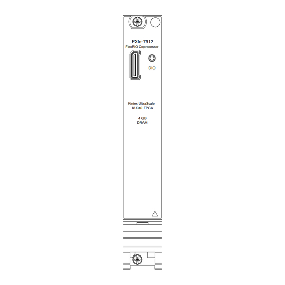
- Page 10 PXIe-7911/7912/7915 Getting Started Figure 3. PXIe-7912 Front Panel PXIe-7912 FlexRIO Coprocessor Kintex UltraScale KU040 FPGA 4 GB DRAM The following table describes the signal connections for the PXIe-7912. Connector Description Function Molex™ Nano-Pitch DIO Multi-signal DIO connector that provides access to FPGA...
- Page 11 PXIe-7911/7912/7915 Getting Started Signal Type Description Ground — Figure 4. PXIe-7915 Front Panel PXIe-7915 FlexRIO Coprocessor Kintex UltraScale KU060 FPGA 4 GB DRAM The following table describes the signal connections for the PXIe-7915. Connector Description Function Molex™ Nano-Pitch DIO Multi-signal DIO connector that provides access to FPGA...
-
Page 12: Configuring The Pxie-7911/7912/7915 In Max
Output Ground — Configuring the PXIe-7911/7912/7915 in MAX Use Measurement & Automation Explorer (MAX) to configure your NI hardware. MAX informs other programs about which NI hardware products are in the system and how they are configured. MAX is automatically installed with FlexRIO Support. -
Page 13: Block Diagram
To access these examples, search FlexRIO examples in the Search the community field at ni.com/examples. Block Diagram The following figure shows the PXIe-7911 block diagram and signal flow. Figure 5. PXIe-7911 Block Diagram Power Supplies 12 V, 3.3 V... -
Page 14: Making A Measurement
KnowledgeBase for additional information our technical support engineers create as they answer common user questions and resolve unexpected issues. What Should I Do if the PXIe-7911/7912/7915 Does Not Appear in MAX? 1. In the MAX configuration tree, expand Devices and Interfaces. -
Page 15: What Should I Do If The Pxie-7911/7912/7915 Fails The Self-Test
4. Navigate to the Device Manager by right-clicking the Start button, and selecting Device Manager. 5. Verify the PXIe-7911/7912/7915 appears in the Device Manager. 1. Under an NI entry, confirm that a PXIe-7911/7912/7915 entry appears. Note If you are using a PC with a device for PXI remote control system, under System Devices, also confirm that no error conditions appear for the PCI-to-PCI Bridge. - Page 16 PXIe-7911/7912/7915 Getting Started NI corporate headquarters is located at 11500 N Mopac Expwy, Austin, TX, 78759-3504, USA. ni.com © 2022 National Instruments Corporation.
Need help?
Do you have a question about the PXIe-7911 and is the answer not in the manual?
Questions and answers