Advertisement
Quick Links
Advertisement

Subscribe to Our Youtube Channel
Related Manuals for National Instruments PXIe-4468


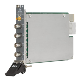
Summary of Contents for National Instruments PXIe-4468
- Page 1 PXIe-4468...
- Page 2 PXIe-4468 Calibration procedure September 2022...
- Page 3 PXIe-4468 Calibration Procedure ni.com/services...
- Page 4 PXIe-4468 Calibration Procedure This document contains the verification and adjustment procedures for the PXIe-4468 with either BNC or mini-XLR connectors. Use the procedures in this document to automate calibration or to conduct manual calibration. Review and become familiar with the entire procedure before beginning the calibration process.
- Page 5 Terms and Definitions DUT is an acronym for Device Under Test and refers to the NI product being calibrated. For this procedure, DUT refers to the PXIe-4468. These limits are derived from the published specifications for the DUT. As-Found Limits...
- Page 6 PXIe-4468 Calibration Procedure Calibration Overview Recommended Calibration Interval 2 years Password Note This is the default password for all password-protected operations. This password is site-specific. Estimated Test Operator Task Test Points Time Connections Setup 10 minutes — — Warm Up 15 minutes —...
- Page 7 PXIe-4468 Calibration Procedure Calibration Condition Guidelines Keep cabling as short as possible. Long cables act as antennas, picking up extra noise that can affect measurements. Ensure that all connections to the DUT are secure. Allow adequate warm up time for all components of the calibration system.
- Page 8 Install the following software on the calibration system: DAQmx Recommended Documentation Go to ni.com/docs to locate the following documentation for more information when performing this calibration: PXIe-4468 Getting Started Guide PXIe-4468 Specifications NI-DAQmx Readme NI-DAQmx Help LabVIEW Help ...
- Page 9 PXIe-4468 Calibration Procedure Recommended Functional Standard Where Used Model Requirement(s) Calibrator Fluke 5730A AI Gain Frequency Range: 40 Hz to 100 kHz AI Flatness Voltage Range: up to 6.3 V Digital Multimeter Keysight (Agilent) AO Differential Offset DC Voltage (DMM)
- Page 10 Complete the following steps to conduct self-calibration using Measurement & Automation Explorer (MAX). Note Disconnect all external signals before beginning self-calibration. Launch MAX. Select My System»Devices and Interfaces»NI PXIe-4468. Start self-calibration using one of the following methods: Click Self-Calibrate in the upper right corner of MAX. ni.com/services...
- Page 11 PXIe-4468 Calibration Procedure Right-click the name of the DUT in the MAX configuration tree and select Self-Calibrate from the drop-down menu. Perform Verification AI Offset Accuracy Verification Test Limits Table 1: AI Offset Verification Limits As-Found Test Limit As-Left Test Limit...
- Page 12 Figure 1. Initial Connection for AI Offset-BNC 1. Calibrator 3. BNC – BNC Cable 2. Banana – BNC Adapter 4. PXIe-4468 with BNC Figure 2. Initial Connection for AI Offset-mXLR 1. Calibrator 3. BNC – mXLR Cable 2. Banana – BNC Adapter 4.
- Page 13 PXIe-4468 Calibration Procedure Configure the calibrator to output 0V DC, with GND engaged. Repeat 6 times, once for each gain setting. Create and configure an AI voltage task on the DUT as shown in Table 2. Table 2: AI Offset Verification Configuration...
- Page 14 PXIe-4468 Calibration Procedure 0.316 -0.316 Start the task. Acquire readings with the DUT. On a per channel basis, average all of the acquired samples. Stop and clear the task. Compare the averaged values to the appropriate limits in Table 1.
- Page 15 PXIe-4468 Calibration Procedure Initial Test Connection Note Initial test connection is same as AI Offset, as shown in Figure 1 or Figure 2. Verification Procedure Complete the following procedure to verify the AI gain accuracy. Repeat 2 times, once for each channel.
- Page 16 PXIe-4468 Calibration Procedure Rate 250000 Samples per channel 125000 *Refer to Table 3 for the maximum and minimum voltages to specify to ensure the specified gain range is used on the module. Start the task. Acquire readings with the DUT.
- Page 17 PXIe-4468 Calibration Procedure 0.99931 * V 1.00069 * V 1kHz 1kHz 0.99713 * V 1.00288 * V 1kHz 1kHz 0.99083 * V 1.00925 * V 1kHz 1kHz Initial Test Connection Note Initial test connection is same as AI Offset, as shown in Figure 1 or Figure 2.
- Page 18 PXIe-4468 Calibration Procedure 1000 0.63 1000 1000 Configure an AI Voltage channel task using the values in Table 8. Table 8: AI Flatness Verification Configuration Configuration Value Physical channel Dev_name/aix Gain* Gain from Table 6 Coupling Terminal Configuration Pseudodifferential Excitation (IEPE)
- Page 19 Lower Limit (mA) Upper Limit (mA) 3.858 4.205 9.655 10.523 19.247 20.976 Initial Test Connection Figure 3. Initial Connection for IEPE Current—BNC 1. DMM 3. BNC – BNC Cable 2. Banana – BNC Adapter 4. PXIe-4468 with BNC © National Instruments Corporation...
- Page 20 Figure 4. Initial Connection for IEPE Current-mXLR 1. DMM 3. BNC – mXLR Cable 2. Banana – BNC Adapter 4. PXIe-4468 with mXLR Verification Procedure Complete the following procedure to verify the IEPE current. Repeat 2 times, once for each channel.
- Page 21 PXIe-4468 Calibration Procedure Terminal Configuration Pseudodifferential Excitation (IEPE) Value from Table 9 Acquisition mode Finite number of samples Rate 200000 Samples Per Channel 125000 *Refer to Table 3 for the maximum and minimum voltages to specify to ensure the specified gain range is used on the module.
- Page 22 1. DMM (Ensure guard to set to LO) 3. BNC – BNC Cable 2. Banana – BNC Adapter 4. PXIe-4468 with BNC Figure 6. Initial Connection for AO Differential Offset-mXLR 1. DMM (Ensure guard to set to LO) 3. BNC – mXLR Cable 2.
- Page 23 PXIe-4468 Calibration Procedure Verification Procedure Complete the following procedure to verify the AO differential offset accuracy. Repeat 2 times, once for each channel. Connect the AO channel under test to the DMM as shown in Figure 5 or Figure 6.
- Page 24 PXIe-4468 Calibration Procedure Set the AO Gain parameter according to the values from Table 14. Table 14: AO Attenuation AO Attenuation (dB) AO Gain (dB) Create an array of 20000 points and fill every element with value 0. Write the array to AO and start the task.
- Page 25 PXIe-4468 Calibration Procedure 0.62783 0.63218 0.62971 0.63029 0.19931 0.20069 0.19991 0.20009 6.27828 6.32180 6.28623 6.31380 1.99310 2.00692 1.99563 2.00438 Pseudodifferential 0.62783 0.63218 0.62862 0.63138 0.19931 0.20069 0.19956 0.20044 Initial Test Connection Note Initial test connection is same as AO Differential Offset, as shown in Figure 5 or Figure 6.
- Page 26 PXIe-4468 Calibration Procedure Range* 10 V RMS Mode (SETACV) 3 (SYNC) AC Bandwidth (ACBAND) 20 Hz Level Filter (LFILTER) 1 (ON) *Refer to Table 17 for details about the correlation between AO Gain, DMM Range, and Signal Amplitude. Table 17: Setting for AO Gain Verification...
- Page 27 PXIe-4468 Calibration Procedure Table 19: Basic Function Generator Parameters Parameter Value Signal Type Sine Wave Frequency 1000 Hz Amplitude* Amplitude from Table 17 Sampling Info>>Sampling Rate 200000 S/s Sampling Info>>Number of Samples 20000 *Refer to Table 17 for details about the correlation between AO Gain, DMM Range, and Signal Amplitude.
- Page 28 PXIe-4468 Calibration Procedure AO Gain Flatness Verification Test Limits Table 20: AO Gain Flatness Verification Limits As-Found Test Limit Device Output Terminal Frequency Lower Limit Upper Limit Gain (dB) Configuration 1 kHz 1kHz Differential 20 kHz 0.999079 * V 1.000921 * V...
- Page 29 PXIe-4468 Calibration Procedure Initial Test Connection Note Initial test connection is same as AO Differential Offset, as shown in Figure 5 or Figure 6. Verification Procedure Complete the following procedure to verify the AO gain flatness. Repeat 2 times, once for each channel.
- Page 30 PXIe-4468 Calibration Procedure *Refer to Table 17 for details about the correlation between AO Gain, DMM Range, and Signal Amplitude. Call DAQmx Channel Property Node, and set the AO Idle Output Behavior property (Analog Output>>General Properties>>Output Configuration>>Idle Output Behavior) to Zero Volts Call Basic Function Generator Parameters using the parameters in Table 22.
- Page 31 5.00442 Initial Test Connection Figure 7. Initial Connection for AO Common-Mode Gain and Offset—BNC 1. DMM 4. BNC – BNC Cable 2. Banana – BNC Adapter 5. PXIe-4468 with BNC 3 Shorting Cable (Banana – Banana) © National Instruments Corporation...
- Page 32 Figure 8. Initial Connection for AO Common-Mode Gain and Offset-mXLR 1. DMM 4. BNC – mXLR Cable 2. Banana – BNC Adapter 5. PXIe-4468 with mXLR 3 Shorting Cable (Banana – Banana) Verification Procedure Complete the following procedure to verify common-mode gain and offset.
- Page 33 PXIe-4468 Calibration Procedure MATH NULL Enabled Configure an AO Voltage channel task using the values in Table 25. Table 25: AO Setup Configuration Value Physical Channels Dev_name/aox Output Terminal Configuration Differential Rate 200000 S/s Sample Mode Continuous Sample Samples Per Channel...
- Page 34 (kHz) (kHz) Limit (kHz) (kHz) 10.000 9.99973 10.00027 9.99992 10.00008 Initial Test Connection Figure 9. Initial Connection for Timebase Frequency-BNC 1. Function Generator 3. PXIe-4468 with BNC 2. BNC – BNC Cable Figure 10. Initial Connection for Timebase Frequency-mXLR ni.com/services...
- Page 35 PXIe-4468 Calibration Procedure 1. Function Generator 3. PXIe-4468 with mXLR 2. BNC – mXLR Cable Verification Procedure Note All analog inputs and outputs on a single device use the same timebase circuitry. Therefore, the measurements made on one channel are valid for both channels.
- Page 36 PXIe-4468 Calibration Procedure Excitation (IEPE) 0 (A) Acquisition mode Finite number of samples Rate 40000.0 Samples per channel 2560000 Start the task. Acquire reading with the DUT. Measure the frequency using the Extract Single Tone Information VI of the acquired signal around 10 kHz. Compare the measured frequency to the limits in Table 27.
- Page 37 PXIe-4468 Calibration Procedure Call DAQmxInitExtCal (DAQmx Initialize External Calibration VI) to initialize the calibration using the following parameters: o deviceName: Dev_name o password: NI o calHandle: &myCalHandle Connect the calibrator to AI0 as shown in Figure 1 or Figure 2.
- Page 38 PXIe-4468 Calibration Procedure Configure the function generator to output a sine wave of 6.3 V (8.9 ) signal, no offset, at a frequency of 90.000 kHz. Call DAQmxAdjustDSADeviceTimebaseCal (DAQmx Adjust DSA Device Timebase Calibration VI) with the following parameters to perform the timebase adjustment: ...
- Page 39 Close the session with the DAQmx Close External Calibration VI with the following parameters: calHandle: myCalHandle action: DAQmx_Val_Action_Commit Revision History Revision Section Changes This is the initial release 378817A-01 — version of the PXIe-4468 September 2022 Calibration Procedure. © National Instruments Corporation...
- Page 40 NI product. Refer to the Export Compliance Information at ni.com/legal/export-compliance for the National Instruments global trade compliance policy and how to obtain relevant HTS codes, ECCNs, and other import/export data. NI MAKES NO EXPRESS OR IMPLIED WARRANTIES AS TO THE ACCURACY OF THE INFORMATION CONTAINED HEREIN AND SHALL NOT BE LIABLE FOR ANY ERRORS.
Need help?
Do you have a question about the PXIe-4468 and is the answer not in the manual?
Questions and answers