National Instruments NI PXIe-8133 User Manual
Hide thumbs
Also See for NI PXIe-8133:
- Installation manual (4 pages) ,
- User manual (92 pages) ,
- Installation manual (2 pages)
Table of Contents
Advertisement
Quick Links
Advertisement
Table of Contents

Related Manuals for National Instruments NI PXIe-8133


Summary of Contents for National Instruments NI PXIe-8133
- Page 1 PXI-8221...
- Page 2 PXI Express NI PXIe-8133 User Manual NI PXIe-8133 User Manual July 2012 372870D-01...
- Page 3 11500 North Mopac Expressway Austin, Texas 78759-3504 USA Tel: 512 683 0100 For further support information, refer to the Technical Support and Professional Services appendix. To comment on National Instruments documentation, refer to the National Instruments Web site at and enter ni.com/info the Info Code feedback ©...
- Page 4 Warranty The NI PXIe-8133 is warranted against defects in materials and workmanship for a period of one year from the date of shipment, as evidenced by receipts or other documentation. National Instruments will, at its option, repair or replace equipment that proves to be defective during the warranty period.
- Page 5 CUSTOMIZED AND DIFFERS FROM NATIONAL INSTRUMENTS' TESTING PLATFORMS AND BECAUSE A USER OR APPLICATION DESIGNER MAY USE NATIONAL INSTRUMENTS PRODUCTS IN COMBINATION WITH OTHER PRODUCTS IN A MANNER NOT EVALUATED OR CONTEMPLATED BY NATIONAL INSTRUMENTS, THE USER OR APPLICATION DESIGNER IS ULTIMATELY...
- Page 6 Furthermore, any changes or modifications to the product not expressly approved by National Instruments could void your authority to operate it under your local regulatory rules.
-
Page 7: Table Of Contents
Chapter 1 Introduction Benefits of PXI Express....................1-1 NI PXIe-8133.........................1-2 Description ......................1-2 Functional Overview ..................1-2 NI PXIe-8133 Functional Description ..........1-2 National Instruments Software ..................1-4 Cleaning .........................1-6 Chapter 2 Installation and Configuration Installing the NI PXIe-8133...................2-1 How to Remove the Controller from the PXI Express Chassis.......2-4 BIOS Setup ........................2-4... - Page 8 DVI-I ....................... 3-3 COM1......................3-5 Ethernet ......................3-6 Parallel Port..................... 3-8 Universal Serial Bus..................3-10 Trigger......................3-11 GPIB (IEEE 488.2) ..................3-12 ExpressCard/34 Slot..................3-14 Front Panel Features ...................... 3-16 Data Storage ........................3-16 NI PXIe-8133 User Manual viii ni.com...
- Page 9 Common Configuration Questions General Questions......................4-1 Boot Options ........................4-2 Cables and Connections....................4-2 Software Driver Installation...................4-3 Upgrade Information......................4-4 PXI Express Configuration ....................4-7 Chapter 5 Troubleshooting Appendix A Specifications Appendix B Technical Support and Professional Services Glossary Index © National Instruments NI PXIe-8133 User Manual...
-
Page 10: About This Manual
National Instruments PXIe-8133 embedded computer kit. How to Use the Documentation Set Begin by reading the NI PXIe-8133 Installation Guide, a brief quick-start guide that describes how to install and get started with your controller. This manual, the NI PXIe-8133 User Manual, contains more details about changing the installation or configuration from the defaults and using the hardware. -
Page 11: Related Documentation
PXI-5 PXI Express Hardware Specification, Revision 1.0, PXI Systems Alliance • PXI-6 PXI Express Software Specification, Revision 1.1, PXI Systems Alliance • Serialized IRQ Support for PCI Systems Specification, Revision 6.0, Compaq Computer et al. • ExpressCard Standard, Release 2.0, PCMCIA NI PXIe-8133 User Manual ni.com... -
Page 12: Introduction
Introduction This chapter provides overview information for PXI Express and the NI PXIe-8133 embedded controller. Benefits of PXI Express The PXI (PCI eXtensions for Instrumentation) industry standard, an open specification governed by the PXI Systems Alliance (PXISA), has quickly gained adoption and grown in prevalence in test, measurement, and control systems since its release in 1998. -
Page 13: Ni Pxie-8133
NI PXIe-8133 embedded computer. NI PXIe-8133 Functional Description The NI PXIe-8133 is a modular PC in a PXI Express 3U-size form factor. Figure 1-1 is a functional block diagram of the NI PXIe-8133. Following the diagram is a description of each logic block shown. - Page 14 Connector Controller Triggers Figure 1-1. NI PXIe-8133 Block Diagram The NI PXIe-8133 consists of the following logic blocks on the CPU module and the I/O (daughter card) module. The CPU module has the following logic blocks: • FPGA Socket189 is the socket definition for the Intel Core i7 processor.
-
Page 15: National Instruments Software
PXI Express/CompactPCI Express backplane. • The Super I/O block represents the other peripherals supplied by the NI PXIe-8133. The NI PXIe-8133 has one serial port, and an ECP/EPP parallel port. • Both the 82577 and 82574 Gigabit Enet ports connect to either 10 Mbit, 100 Mbit, or 1,000 Mbit Ethernet interfaces. - Page 16 NI-Sync. For more information visit ni.com/pxi NI-VISA is the National Instruments implementation of the VISA specification. VISA is a uniform API for communicating and controlling USB, Serial, GPIB, PXI, PXI Express, VXI, and various other types of instruments.
-
Page 17: Cleaning
NI-VISA driver for Linux and NI Modular Instruments are partially supported. For more information visit ni.com/linux Cleaning Use a dry, low-velocity stream of air to clean the NI PXIe-8133 controller. If needed, use a soft-bristle brush for cleaning around components. NI PXIe-8133 User Manual ni.com... -
Page 18: Installation And Configuration
NI PXIe-8133 controller. Installing the NI PXIe-8133 This section contains general installation instructions for the NI PXIe-8133. Consult your PXI Express chassis user manual for specific instructions and warnings. Plug in your chassis before installing the NI PXIe-8133. The power cord grounds the chassis and protects it from electrical damage while you install the module. - Page 19 1 Protective Screw Cap (4x) Figure 2-1. Removing Protective Screw Caps Make sure the injector/ejector handle is in its downward position. Align the NI PXIe-8133 with the card guides on the top and bottom of the system controller slot. Caution Do not raise the injector/ejector handle as you insert the NI PXIe-8133.
- Page 20 Chapter 5, What if the NI PXIe-8133 does not boot? Troubleshooting. Figure 2-2 shows an NI PXIe-8133 installed in the system controller slot of a National Instruments NI PXIe-1082 chassis. 1 NI PXIe-1082 Chassis 3 Injector/Ejector Rail 2 NI PXIe-8133 Controller Figure 2-2.
-
Page 21: How To Remove The Controller From The Pxi Express Chassis
If the PXI Express chassis Inhibit Mode Selector Switch is not in the Default position, any attempt to shut down the NI PXIe-8133 through the push button reset or using Windows will result in the controller Power OK LED blinking. The user will be required to use the Remote Inhibit pin on the Remote Inhibit and Voltage Monitoring Connector to turn off the chassis. -
Page 22: Main Menu
The Main menu reports the following configuration information: • BIOS Version and Build Date—These values indicate the version of the NI PXIe-8133 controller BIOS and the date on which the BIOS was built. • Processor Type, Processor Base Frequency, and Processor Core—These values indicate the type of processor used in the... -
Page 23: Advanced Menu
Power/Wake Configuration submenu. Refer to the Power/Wake Configuration Submenu section for more information. • Clock Generator Configuration—Use this setting to access the Clock Generator Configuration submenu. Refer to the Clock Generator Configuration Submenu section for more information. NI PXIe-8133 User Manual ni.com... -
Page 24: Pci Subsystem Settings Submenu
AHCI mode and enable IDE mode so that non-compatible OSes function correctly. The default value is AHCI. • Internal Drive (SATA)—This item displays the onboard SATA drive detected in the system. © National Instruments NI PXIe-8133 User Manual... -
Page 25: Cpu Configuration Submenu
The default value is Enabled when booting LabVIEW Real-Time, enabled when booting other OSs. Enabling hardware prefetching can increase system performance for some applications, but can cause control algorithms to behave less deterministically. NI PXIe-8133 User Manual ni.com... -
Page 26: Video Configuration Submenu
The Disable option should only be used in conjunction with the PXI Express chassis’ inhibit mode switch. • ExpressCard WAKE#—This setting enables or disables an ExpressCard device’s ability to wake a powered-off system. The default value is Disabled. © National Instruments NI PXIe-8133 User Manual... -
Page 27: Clock Generator Configuration Submenu
Reserved Memory—This setting determines the amount of memory space, in bytes, that will be reserved by the BIOS for PCI-PCI bridges that may be hot-plugged in the ExpressCard slot. The default value for this setting is 64M bytes of memory. NI PXIe-8133 User Manual 2-10 ni.com... -
Page 28: Usb Configuration Submenu
Power-On Self Test will wait for a USB device or hub to power on. This setting is only visible if Device Power-Up Delay is set to Manual. The default is 5 seconds. © National Instruments 2-11 NI PXIe-8133 User Manual... -
Page 29: Serial/Parallel Port Configuration Submenu
Change Settings—This setting changes the base address and interrupt request level (IRQ) information for the onboard parallel port. The default value is Auto. Note that the options available vary based upon the Device Mode selected for the parallel port. NI PXIe-8133 User Manual 2-12 ni.com... -
Page 30: Labview Rt Menu
Boot Configuration, Reset IP Address, and Disable Startup VI switch status. For more information on these settings and the switches that control them, refer to the LabVIEW RT Configuration Switches section of this chapter. © National Instruments 2-13 NI PXIe-8133 User Manual... -
Page 31: Labview Rt Configuration Overrides Submenu
Only one device of a given type will be shown in this list. If more than one device of the same type exists, use the Device BBS Priorities submenus to re-order the priority of devices of the same type. NI PXIe-8133 User Manual 2-14 ni.com... -
Page 32: Boot Settings Configuration Submenu
The highest priority device is displayed on the main Boot Option Priorities list. Optionally, each device can also be Disabled if the device should never be used as a boot device. © National Instruments 2-15 NI PXIe-8133 User Manual... -
Page 33: Cd/Dvd Rom Drive Bbs Priorities Submenu
User’s password is set, then this is a power on password and must be entered to boot or enter the BIOS setup program. In the BIOS setup program, the User will have Administrator rights. By default, no password is specified. NI PXIe-8133 User Manual 2-16 ni.com... -
Page 34: Save & Exit Menu
If BIOS setup options have been changed and saved, a reboot will be required and the boot override selection will not be valid. © National Instruments 2-17 NI PXIe-8133 User Manual... -
Page 35: Bios Diagnostic Utilities
Note If the memory test fails, the controller is not permitted to boot, and the user is instructed to turn off the controller and replace the memory. NI PXIe-8133 User Manual 2-18 ni.com... -
Page 36: System Cmos
Chapter 2 Installation and Configuration System CMOS The NI PXIe-8133 contains memory backed up by a battery to store BIOS configuration information. Complete the following steps to clear the CMOS contents: Power off the chassis. Remove the controller from the chassis. -
Page 37: Labview Rt Installation
Click on the appropriate PXI Express controller entry to access the Network Settings tab in the right pane view. (Optional) Enter a name for the RT target in the Name text box. NI PXIe-8133 User Manual 2-20 ni.com... -
Page 38: Labview Rt Configuration Switches
If you are not using LabVIEW RT, these switches should remain in the OFF position. The controller reads these switches only after a system reset. Note You must reboot the controller for any changes to take place. © National Instruments 2-21 NI PXIe-8133 User Manual... - Page 39 Chapter 2 Installation and Configuration The NI PXIe-8133 controller includes the following LabVIEW RT configuration switches: • Switch 1—Boot LabVIEW RT: Set this switch to ON to boot LabVIEW RT. Switch 2—Boot Safe Mode: Set this switch to ON to boot LabVIEW •...
-
Page 40: Drivers And Software
National Instruments software manuals, all in Adobe Acrobat format. To access any manual, change your directory and list the contents of that directory. c:\images\manuals directory contains a subdirectory corresponding to the operating system installed on your computer. -
Page 41: Pxi Express Features
PXI Express Features PXI Express Trigger Connectivity The SMB connector on the NI PXIe-8133 front panel can connect to or from any PXI Express backplane trigger line. A trigger allocation process is needed to prevent two resources from connecting to the same trigger line, resulting in the trigger being double-driven and possibly damaging the hardware. -
Page 42: Upgrading Ram
PXI Express specification at www.pxisa.org Upgrading RAM You can change the amount of installed RAM on the NI PXIe-8133 by upgrading the SO-DIMMs. To upgrade the RAM, remove the NI PXIe-8133 from the PXI Express chassis. To optimize both memory capacity and system performance, use the same size and speed memory module in each of the two module slots. - Page 43 Notes National Instruments has tested and verified that the DDR3 SO-DIMMs we sell work with the NI PXIe-8133. We recommend you purchase your DDR3 SO-DIMM modules from National Instruments. Other off-the-shelf DDR3 SO-DIMM modules are not guaranteed to work properly.
-
Page 44: Hard Drive Recovery
Installing from a USB CD/DVD-ROM The NI PXIe-8133 supports the installation of Windows 7 or Windows XP from a USB CD/DVD-ROM. As an alternative to a USB CD/DVD-ROM drive, you can use an external SCSI CD-ROM with a PXI-SCSI adapter. -
Page 45: Expresscard
Slide the card out of the slot. Caution To avoid data loss and other potential issues, stop communication with your ExpressCard device before removing it from the NI PXIe-8133. In Windows, use the Safely Remove Hardware tool to safely stop the ExpressCard. NI PXIe-8133 User Manual 2-28 ni.com... -
Page 46: I/O Information
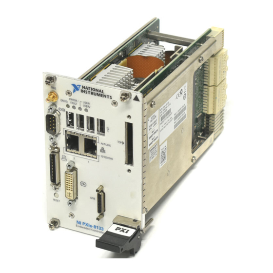
I/O Information Front Panel Connectors Table 3-1 lists various peripherals and their corresponding NI PXIe-8133 external connectors, bus interfaces, and functions. Table 3-1. NI PXIe-8133 Peripherals Overview Peripheral External Connector Description Video DVI-I ATI Radeon E2400 Embedded GPU (24-pin DSUB) -
Page 47: Front Panel
3.003 in. [76.43 mm] 2.064 in. [52.43 mm] 1.65 in. [41.91 mm] 1.256 in. [31.9 mm] 1.070 in. [27.18 mm] NI PXIe-8133 Embedded Controller 0.000 in. [0 mm] Figure 3-1. NI PXIe-8133 Front Panel Layout and Dimensions NI PXIe-8133 User Manual ni.com... -
Page 48: Dvi-I
Chapter 3 I/O Information DVI-I Figure 3-2 shows the location and pinouts for the DVI connector on the NI PXIe-8133. Table 3-2 lists and describes the DVI connector signals. NI PXIe-8133 Embedded Controller Figure 3-2. DVI Connector Location and Pinout Table 3-2. - Page 49 Hot Plug Detect TMDS Data0– TMDSData0+ TMDS Data0/5 Shield Reserved Reserved TMDS Clock Shield TMDS Clock + TMDS Clock – Analog Red Analog Green Analog Blue Analog Horizontal Sync Analog GND Return: (analog R, G, B) NI PXIe-8133 User Manual ni.com...
-
Page 50: Com1
I/O Information COM1 Figure 3-3 shows the location and pinouts for the COM1 connector on the NI PXIe-8133. Table 3-3 lists and describes the COM1 connector signal. AMP manufactures a serial port mating connector, part number 745491-5. COM1 NI PXIe-8133 Embedded Controller Figure 3-3. -
Page 51: Ethernet
Chapter 3 I/O Information Ethernet Figure 3-4 shows the location and pinouts for the dual stacked Ethernet connector on the NI PXIe-8133. Table 3-4 lists and describes the Ethernet connector signals. AMP manufactures a mating connector, part number 554739-1. Ethernet... - Page 52 The controller is communicating with another computer on the LAN. (None) 10 Mbit/sec data rate is selected. 10/100/ Green 100 Mbit/sec data rate is selected. 1000 Amber 1000 Mbit/sec data rate is selected. © National Instruments NI PXIe-8133 User Manual...
-
Page 53: Parallel Port
I/O Information Parallel Port Figure 3-5 shows the location and pinouts for the IEEE 1284 (parallel) connector on the NI PXIe-8133. Table 3-6 lists and describes the IEEE 1284 connector signals. Parallel port adapter cables are available from National Instruments, part number 777169-01. - Page 54 Data Bit 6 Data Bit 7 INIT# Initialize Printer STROBE# Strobe SLCTIN# Select Input AUTOFD# Auto Line Feed +5 V 19–35 Ground Not Connected Note: The pound symbol (#) indicates an active low signal. © National Instruments NI PXIe-8133 User Manual...
-
Page 55: Universal Serial Bus
Universal Serial Bus Figure 3-6 shows the location and pinouts for the Universal Serial Bus (USB) connector on the NI PXIe-8133. Each controller has 4 USB ports on the front panel. Table 3-7 lists and describes the USB connector signals. -
Page 56: Trigger
The TRIG connector is the software-controlled trigger connection for routing PXI Express triggers to or from the backplane trigger bus. Figure 3-7 shows the TRIG connector location on the NI PXIe-8133. Table 3-8 lists and describes the trigger connector signals. -
Page 57: Gpib (Ieee 488.2)
Chapter 3 I/O Information GPIB (IEEE 488.2) Figure 3-8 shows the location and pinouts for the GPIB connector on the NI PXIe-8133. Table 3-9 lists and describes the GPIB connector signals. ITT Canon manufactures a GPIB mating connector, part number MDSM-25SC-Z11-V51. - Page 58 DIO5# Data Bit 5 DIO6# Data Bit 6 DIO7# Data Bit 7 DIO8# Data Bit 8 REN# Remote Enable 18–25 Logic Ground Note: The pound symbol (#) indicates an active low signal. © National Instruments 3-13 NI PXIe-8133 User Manual...
-
Page 59: Expresscard/34 Slot
Chapter 3 I/O Information ExpressCard/34 Slot The NI PXIe-8133 controller is equipped with an ExpressCard/34 slot on the front panel, which provides I/O expansion and options for removable storage. Figure 3-9 shows the location and pinouts for the ExpressCard/34 slot on the NI PXIe-8133. - Page 60 PERn0 PE Data Receive – PERp0 PE Data Receive + Ground PETn0 PE Data Transmit – PETp0 PE Data Transmit + Ground Note: The pound symbol (#) indicates an active low signal. © National Instruments 3-15 NI PXIe-8133 User Manual...
-
Page 61: Front Panel Features
– The DRIVE LED indicates when an access to the internal hard disk is occurring. Data Storage The NI PXIe-8133 has the following data storage features: • Internal Serial ATA hard drive – 120 GB or larger 2.5 in. notebook hard drive –... -
Page 62: Common Configuration Questions
This chapter answers common configuration questions you may have when using a NI PXIe-8133 embedded controller. General Questions What do the LEDs on the NI PXIe-8133 front panel mean? Refer to the LED status descriptions in the Front Panel Features... -
Page 63: Boot Options
There are some limitations when booting from a USB device. Windows 7 and Windows XP can be installed from a USB CD/DVD-ROM, but earlier versions of Windows cannot. The NI PXIe-8133 BIOS configures the USB devices so that they will work in a DOS environment. -
Page 64: Software Driver Installation
If you do not have a Y-splitter cable, plug a USB keyboard into any USB connector. You can also plug a USB mouse into any USB connector. How do I connect a standard 25-pin LPT cable to the NI PXIe-8133? The NI PXIe-8133 uses a type C LPT connector. Most parallel port devices use a type A connector. -
Page 65: Upgrade Information
Common Configuration Questions How do I install software from a CD? The compact size of the NI PXIe-8133 does not allow for an integrated USB CD/DVD-ROM drive. If you are using Windows 7 or Windows XP, you have the following options: •... - Page 66 Notes National Instruments has tested and verified that the DDR3 SO-DIMMs we sell work with the NI PXIe-8133. We recommend you purchase your DDR3 SO-DIMM modules from National Instruments. Other off-the-shelf DDR3 SO-DIMM modules are not guaranteed to work properly.
- Page 67 Chapter 4 Common Configuration Questions What is the purpose of the W1 jumper on the NI PXIe-8133? 1 Default Position 2 Reserved Figure 4-3. The W1 Jumper on an NI PXIe-8133 Controller The W1 jumper enables reserved features for National Instruments factory testing only.
-
Page 68: Pxi Express Configuration
Chapter 4 Common Configuration Questions My NI PXIe-8133 does not have an internal floppy drive. Is there a way to use an external drive? Yes. The NI PXIe-8133 controller supports and can boot from USB floppy drives. Refer to the section for more information. -
Page 69: Troubleshooting
This chapter answers common troubleshooting questions you may have when using the NI PXIe-8133 embedded computer. What if the NI PXIe-8133 does not boot? Several problems can cause a controller not to boot. Here are some things to look for and possible solutions. - Page 70 Press <F9> to load BIOS defaults. Answer Y (Yes) to the verification prompt. Select Save and Exit Setup. As an alternative method, complete the following steps: Power off the chassis. Remove the controller from the chassis. NI PXIe-8133 User Manual ni.com...
- Page 71 Chapter 5 Troubleshooting Press the Clear CMOS button (SW2) as shown in Figure 5-1. Wait one second. Reinstall the controller in the chassis. 1 Push-Button Switch SW2 Figure 5-1. Clearing the CMOS Contents © National Instruments NI PXIe-8133 User Manual...
-
Page 72: Appendix A Specifications
Specifications This appendix lists the electrical, mechanical, and environmental specifications of the NI PXIe-8133 embedded controller. Features NI PXIe-8133 Intel Core i7 820 QM CPU Frequency 1.73 GHz (base), 3.06 GHz (single-core Turbo mode) On-die L2 cache 512 KB x2 (512 KB per core) - Page 73 (at 25 °C ambient temperature) Pollution Degree ........2 Indoor use only. Caution Clean the NI PXIe-8133 with a soft nonmetallic brush. Make sure that the device is completely dry and free from contaminants before returning it to service. NI PXIe-8133 User Manual ni.com...
- Page 74 Standard ........–40 to 65 °C (Tested in accordance with IEC-60068-2-1 and IEC-60068-2-2. Meets MIL-PRF-28800F Class 3 low temperature limit.) Processor should not throttle CPU frequency under reasonable, worst case processor work loads in high operating temperatures. © National Instruments NI PXIe-8133 User Manual...
- Page 75 • IEC 61010-1, EN 61010-1 • UL 61010-1, CSA 61010-1 Note For UL and other safety certifications, refer to the product label or the Online Product Certification section. NI PXIe-8133 User Manual ni.com...
- Page 76 Environmental Management NI is committed to designing and manufacturing products in an environmentally responsible manner. NI recognizes that eliminating certain hazardous substances from our products is beneficial to the environment and to NI customers. © National Instruments NI PXIe-8133 User Manual...
- Page 77 This device contains a long-life coin cell battery. If you need to replace it, use the Return Cd/Hg/Pb Material Authorization (RMA) process or contact an authorized National Instruments service representative. For more information about compliance with the EU Battery Directive 2006/66/EC about Batteries and Accumulators and Waste Batteries and Accumulators, visit ni.com/environment/batterydirective...
- Page 78 Technical Support and Professional Services Log in to your National Instruments User Profile to get ni.com personalized access to your services. Visit the following sections of for technical support and professional services: ni.com • Support—Technical support at includes the ni.com/support following resources: Self-Help Technical Resources—For answers and solutions,...
- Page 79 Appendix B Technical Support and Professional Services System Integration—If you have time constraints, limited in-house • technical resources, or other project challenges, National Instruments Alliance Partner members can help. To learn more, call your local NI office or visit ni.com/alliance •...
- Page 80 BIOS Basic Input/Output System—BIOS functions are the fundamental level of any PC or compatible computer. BIOS functions embody the basic operations needed for successful use of the computer’s hardware resources. © National Instruments NI PXIe-8133 User Manual...
- Page 81 LCD computer displays and digital projectors. It was developed by an industry consortium, the Digital Display Working Group (DDWG). Extended Capabilities Parallel. EEPROM Electronically Erasable Programmable Read Only Memory. Electromagnetic Compatibility. Electromagnetic interference. NI PXIe-8133 User Manual ni.com...
- Page 82 LabWindows/CVI or LabVIEW. interrupt A means for a device to request service from another device. interrupt level The relative priority at which a device can interrupt. © National Instruments NI PXIe-8133 User Manual...
- Page 83 Mean time between failure. NI-488 or NI-488.2 The National Instruments software for GPIB systems. NI-DAQ The National Instruments software for data acquisition instruments. NI-VISA The National Instruments implementation of the VISA standard—An interface-independent software that provides a unified programming interface for VXI, GPIB, and serial instruments.
- Page 84 SO-DIMM Small Outline Dual In-line Memory Module. SPI Bus Serial Peripheral Interface—A standard for controlling most any digital electronics that accept a clocked serial stream of bits. © National Instruments NI PXIe-8133 User Manual...
- Page 85 Glossary Universal Serial Bus. Volts. Video Graphics Array—The minimum video display standard for all PCs. Watts. NI PXIe-8133 User Manual ni.com...
- Page 86 2-14 configuration, PXI Express chassis, 2-24 Main menu, 2-5 connectors Network Device BBS Priorities COM1 connector and signals, 3-5 Configuration menu, 2-16 DVI connector and signals, 3-3 PCI Subsystem Settings menu, 2-7 © National Instruments NI PXIe-8133 User Manual...
- Page 87 2-28 installing, 4-4 module connector, 3-1 figure, 2-26, 4-5 removing a module, 2-28 DDR3 SO-DIMMs from National Instruments (note), 2-26, 4-5 Declaration of Conformity (NI resources), B-2 diagnostic tools (NI resources), B-1 features of PXI Express, 2-24...
- Page 88 IEEE 488.2, 3-12 LEDs, front panel LEDs, 3-16, 4-1 images directory, 2-23 Linux support, 1-6 installation LPT cable, connecting to NI PXIe-8133, 4-3 See also configuration injector/ejector handle position (caution), 2-2 NI PXIe-8133 installed in a PXI Express Main menu, 2-5...
- Page 89 (logic block), 1-4 installing in a PXI Express chassis, 2-1 features, 2-24 figure, 2-3 trigger connectivity, 2-24 logic blocks, 1-3 trigger connector, 3-1 peripheral expansion overview (table), 3-1 PXI Express trigger connectivity, 2-24 NI PXIe-8133 User Manual ni.com...
- Page 90 Serial/Parallel Port Configuration menu, 2-12 Parallel Port menu, 2-12 Serial Port menu, 2-12 technical support, B-1 setting up the NI PXIe-8133 BIOS, 2-4 training and certification (NI resources), B-1 shock and vibration specifications, A-4 trigger, 4-7 SO-DIMM logic block, 1-3...
- Page 91 4-3 using mouse and keyboard without, 4-3 using with PS/2 mouse and keyboard, 2-3 location and pinout (figure), 3-3 overview (table), 3-1 video, 3-1 See also VGA driver installation, 4-3 Video Configuration menu, 2-9 NI PXIe-8133 User Manual ni.com...
Need help?
Do you have a question about the NI PXIe-8133 and is the answer not in the manual?
Questions and answers