
Related Manuals for National Instruments PXI Express PXIe-1085 Series


Summary of Contents for National Instruments PXI Express PXIe-1085 Series
- Page 1 (217) 352-9330 | Click HERE Find the National Instruments PXIe-1085 at our website:...
- Page 2 PXI Express NI PXIe-1085 Series User Manual NI PXIe-1085 Series User Manual June 2018 373712J-01 Artisan Technology Group - Quality Instrumentation ... Guaranteed | (888) 88-SOURCE | www.artisantg.com...
- Page 3 NI Services appendix. To comment on NI documentation, refer to the NI website at and enter the Info Code ni.com/info feedback © 2012–2018 National Instruments. All rights reserved. Artisan Technology Group - Quality Instrumentation ... Guaranteed | (888) 88-SOURCE | www.artisantg.com...
- Page 4 National Instruments Corporation. National Instruments respects the intellectual property of others, and we ask our users to do the same. NI software is protected by copyright and other intellectual property laws. Where NI software may be used to reproduce software or other materials belonging to others, you may use NI software only to reproduce materials that you may reproduce in accordance with the terms of any applicable license or other legal restriction.
- Page 5 The ExpressCard ™ word mark and logos are owned by PCMCIA and any use of such marks by National Instruments is under license. The mark LabWindows is used under a license from Microsoft Corporation. Windows is a registered trademark of Microsoft Corporation in the United States and other countries.
-
Page 6: Table Of Contents
Rack Mounting ......................... 2-5 Connecting Safety Ground ....................2-6 Connecting to Power Source .................... 2-6 Installing a PXI Express System Controller ..............2-7 © National Instruments | v Artisan Technology Group - Quality Instrumentation ... Guaranteed | (888) 88-SOURCE | www.artisantg.com... - Page 7 Contents Installing Peripheral Modules ...................2-8 Remote System Monitoring ....................2-9 Default Configuration Settings ................. 2-10 Front Panel and Fan Module LED Indicators ..............2-11 Remote Voltage Monitoring and Control ................. 2-12 Inhibit Mode Switch ......................2-14 PXI_CLK10 Front Panel Connectors ................2-14 PXI Express System Configuration with MAX..............
- Page 8 NI PXIe-1085 Series User Manual Glossary Index © National Instruments | vii Artisan Technology Group - Quality Instrumentation ... Guaranteed | (888) 88-SOURCE | www.artisantg.com...
-
Page 9: About This Manual
• PCI Express Base Specification, Revision 1.1, PCI Special Interest Group • PXI-5 PXI Express Hardware Specification, Revision 2.0, PXI Systems Alliance © National Instruments | ix Artisan Technology Group - Quality Instrumentation ... Guaranteed | (888) 88-SOURCE | www.artisantg.com... -
Page 10: Getting Started
Getting Started This chapter describes the key features of the NI PXIe-1085 Series chassis and lists the kit contents and optional equipment you can order from National Instruments. Unpacking Carefully inspect the shipping container and the chassis for damage. Check for visible damage to the metal work. -
Page 11: Key Features
BS 1363/IEC83 If you are missing any of the items listed in Table 1-1, or if you have the incorrect AC power cable, contact National Instruments. Key Features The NI PXIe-1085 Series chassis combines a high-performance 18-slot PXI Express backplane with a high-output power supply and a structural design that has been optimized for maximum usability in a wide range of applications. -
Page 12: Chassis Description
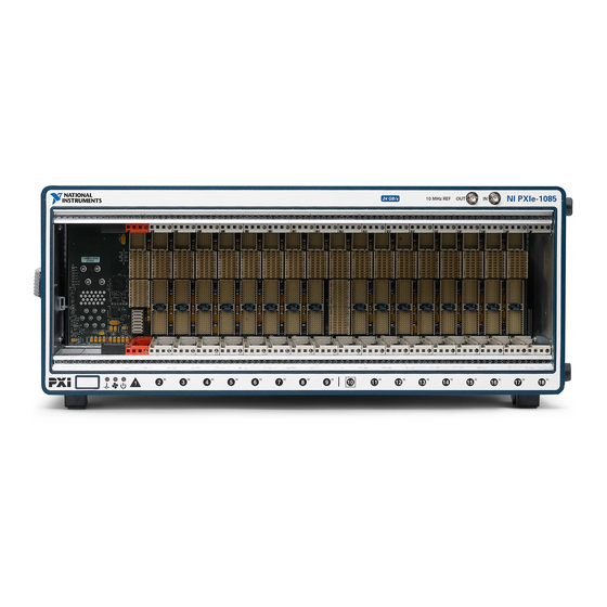
10 MHz REF OUT SMA connector. The NI PXIe-1085 12 GB/s chassis does not have this mark. © National Instruments | 1-3 Artisan Technology Group - Quality Instrumentation ... Guaranteed | (888) 88-SOURCE | www.artisantg.com... - Page 13 Chapter 1 Getting Started Figure 1-1. Front View of the NI PXIe-1085 Series Chassis NI PXIe-1085 12 11 Chassis Carry Handle PXI Express Hybrid Peripheral Slots (16x) Backplane Connectors PXI Express System Timing Slot 10 MHz REF OUT SMA 10 PXI Express System Controller Slot 10 MHz REF IN SMA 11 Temperature, Fan, and Power LEDs PXI Filler Panels...
-
Page 14: Optional Equipment
NI PXIe-1085 Series User Manual Optional Equipment Contact National Instruments to order the following options for the NI PXIe-1085 Series chassis. EMC Filler Panels Optional EMC filler panel kits are available from National Instruments. Rack Mount Kit There are two required kits for mounting the NI PXIe-1085 Series chassis into a rack. The first is a pair of mounting brackets for use on the front of the chassis. -
Page 15: System Controller Slot
Chapter 1 Getting Started System Controller Slot NI PXIe-1085 12 GB/s The system controller slot is Slot 1 of the chassis and is a 2-Link configuration system slot as defined by the CompactPCI Express and PXI Express specifications. It has three system controller expansion slots for system controller modules that are wider than one slot. -
Page 16: Ni Pxie-1085 24 Gb/S
Refer to the Inhibit Mode Switch section of Chapter 2, Installation and Configuration, for details about the Inhibit Mode switch. © National Instruments | 1-7 Artisan Technology Group - Quality Instrumentation ... Guaranteed | (888) 88-SOURCE | www.artisantg.com... -
Page 17: Hybrid Peripheral Slots
Chapter 1 Getting Started Hybrid Peripheral Slots The chassis provides 16 hybrid peripheral slots as defined by the PXI-5 PXI Express Hardware Specification: slots 2-9 and slots 11-18. A hybrid peripheral slot can accept the following peripheral modules: • NI PXIe-1085 12 GB/s—A PXI Express peripheral with x8, x4, or x1 PCI Express link through a switch to the system slot. -
Page 18: System Timing Slot
The system timing slot has a pin (PXI_CLK10_IN) through which a system timing module may source a 10 MHz clock to which the backplane will phase-lock. Refer to the System Reference Clock section for details. © National Instruments | 1-9 Artisan Technology Group - Quality Instrumentation ... Guaranteed | (888) 88-SOURCE | www.artisantg.com... -
Page 19: Pxi Local Bus
Chapter 1 Getting Started The system timing slot has a pin (PXIe_SYNC_CTRL) through which a system timing module can control the PXIe_SYNC100 timing. Refer to the PXI Express Specification and the PXIe_SYNC_CTRL section of this chapter for details. Figure 1-5. PXI Express Star Connectivity Diagram STAR STAR 10 DSTAR 1... -
Page 20: System Reference Clock
NI PXIe-1085 Series User Manual (MAX). Dynamic routing of triggers (automatic line assignments) is supported through certain National Instruments drivers like NI-DAQmx. Although any trigger line may be routed in either direction, it cannot be Note routed in more than one direction at a time. - Page 21 Chapter 1 Getting Started on this pin, the backplane automatically phase-locks the PXI_CLK10, PXIe_CLK100, and PXIe_SYNC100 signals to this external clock and distributes these signals to the slots. Refer to Appendix A, Specifications, for the specification information for an external clock provided on the PXI_CLK10_IN pin of the system timing slot.
- Page 22 PXIe_SYNC100 in phase with each other. Refer to Figure 1-8 for timing details with this method. Figure 1-8. PXIe_SYNC100 at 3.33 MHz Using PXIe_SYNC_CTRL as Restart PXI_CLK10 PXIe_SYNC_CTRL PXIe_SYNC100 SYNC100 Divider Restarted Here © National Instruments | 1-13 Artisan Technology Group - Quality Instrumentation ... Guaranteed | (888) 88-SOURCE | www.artisantg.com...
-
Page 23: Installation And Configuration
• Part Replacement—Only service this equipment with parts that are exact replacements, both electrically and mechanically. Contact National Instruments for replacement part information. Installation of parts with those that are not direct replacements may cause harm to personnel operating the chassis. Furthermore, damage or fire may occur if replacement parts are unsuitable. -
Page 24: Chassis Cooling Considerations
Chapter 2 Installation and Configuration Chassis Cooling Considerations The NI PXIe-1085 Series chassis is designed to operate on a bench or in an instrument rack. The chassis must be oriented horizontally for benchtop use. Vertical orientation with the chassis handle up is not a supported configuration. Regardless of the configuration, you must provide the cooling clearances as outlined in the following sections. - Page 25 Figure 2-2. NI PXIe-1085 Series Chassis Vents Primary Air Intake Vent (3x) Secondary Air Intake/Exhaust Vents (Both Sides) Primary Air Exhaust Vent © National Instruments | 2-3 Artisan Technology Group - Quality Instrumentation ... Guaranteed | (888) 88-SOURCE | www.artisantg.com...
-
Page 26: Chassis Ambient Temperature Definition
Chapter 2 Installation and Configuration Chassis Ambient Temperature Definition The chassis fan control system uses intake air temperature as the input for controlling fan speeds when in Auto Fan Speed mode. Because of this, the chassis ambient temperature is defined as the temperature that exists just outside of the fan intake vents on the rear of the chassis. -
Page 27: Securing Front Panel
You may want to remove the feet from the NI PXIe-1085 Series chassis when Note rack mounting. To do so, remove the screws holding the feet in place. © National Instruments | 2-5 Artisan Technology Group - Quality Instrumentation ... Guaranteed | (888) 88-SOURCE | www.artisantg.com... -
Page 28: Connecting Safety Ground
Chapter 2 Installation and Configuration Connecting Safety Ground The NI PXIe-1085 Series chassis are designed with a three-position Caution NEMA 5-15 style plug for the U.S. that connects the ground line to the chassis ground. To minimize shock hazard, make sure the electrical power outlet you use to power the chassis has an appropriate earth safety ground. -
Page 29: Installing A Pxi Express System Controller
Power on the chassis. Verify that the system controller boots. If the system controller does not boot, refer to your system controller user manual. © National Instruments | 2-7 Artisan Technology Group - Quality Instrumentation ... Guaranteed | (888) 88-SOURCE | www.artisantg.com... -
Page 30: Installing Peripheral Modules
Chapter 2 Installation and Configuration Figure 2-5 shows a PXI Express system controller installed in the system controller slot of a NI PXIe-1085 Series chassis. You can place CompactPCI, CompactPCI Express, PXI, or PXI Express modules in other slots depending on the slot type. Figure 2-5. -
Page 31: Remote System Monitoring
To use the remote monitoring interface, connect one end of an Ethernet cable to your NI PXIe-1085 Series chassis. Connect the other end of the cable to your Ethernet network. © National Instruments | 2-9 Artisan Technology Group - Quality Instrumentation ... Guaranteed | (888) 88-SOURCE | www.artisantg.com... -
Page 32: Default Configuration Settings
Chapter 2 Installation and Configuration The Ethernet controller can perform automatic crossover, thus eliminating the Note need for crossover cables. Through the remote monitoring Ethernet interface of the chassis, you can access a web page with information about the current chassis operating parameters. You can access this page in most browsers. -
Page 33: Front Panel And Fan Module Led Indicators
Blinking red Power supply is active, and at least one voltage is out of range. Steady red Power supply has failed. © National Instruments | 2-11 Artisan Technology Group - Quality Instrumentation ... Guaranteed | (888) 88-SOURCE | www.artisantg.com... -
Page 34: Remote Voltage Monitoring And Control
Chapter 2 Installation and Configuration Figure 2-9 shows a fan module LED. Table 2-3 describes the LED states. Figure 2-9. Fan Module LED Fan Module LED Table 2-3. Fan Module LED States State Description Fan module LED Chassis is powered off. Steady green Fan is operating normally. - Page 35 Table 2-5. Use the rear-panel 8-pin connector to check voltages only. Do not use the Note connector to supply power to external devices. © National Instruments | 2-13 Artisan Technology Group - Quality Instrumentation ... Guaranteed | (888) 88-SOURCE | www.artisantg.com...
-
Page 36: Inhibit Mode Switch
Chapter 2 Installation and Configuration Table 2-5. Power Supply Voltages at Voltage Monitoring Connector Supply Acceptable Voltage Range +5 V 4.75 to 5.25 V +3.3 V 3.135 to 3.465 V +12 V 11.4 to 12.6 V -12 V -12.6 to -11.4 V 3, 8 Logic Ground If the voltages fall within the specified ranges, the chassis complies with the CompactPCI... -
Page 37: Pxi Express System Configuration With Max
PXI System branch shows all devices in the system that can be recognized by NI-VISA. When your system controller and all your chassis are identified, the required file is complete. pxisys.ini © National Instruments | 2-15 Artisan Technology Group - Quality Instrumentation ... Guaranteed | (888) 88-SOURCE | www.artisantg.com... -
Page 38: Trigger Configuration In Max
Dynamic reservation/routing/deallocation is on the fly within a user program based upon National Instruments APIs such as NI-DAQmx. Static reservation of trigger lines can be implemented by the user in MAX through the Triggers tab. -
Page 39: Pxi Trigger Bus Routing
NI PXIe-1085 Series User Manual PXI Trigger Bus Routing Some National Instruments chassis, such as the NI PXIe-1085 Series and the NI PXI-1044/1045, have the capability to route triggers from one bus to others within the same chassis using the Trigger Routing tab in MAX, as shown in Figure 2-10. -
Page 40: Maintenance
Use a dry, low-velocity stream of air to clean the interior of the chassis. Use a soft-bristle brush for cleaning around components. © National Instruments | 3-1 Artisan Technology Group - Quality Instrumentation ... Guaranteed | (888) 88-SOURCE | www.artisantg.com... -
Page 41: Exterior Cleaning
Installation and Configuration. If the power switch LED is not a steady green, contact National Instruments. Verify that the NI PXIe-1085 Series chassis can meet the power requirements of your CompactPCI or PXI Express modules. Overloading the chassis can cause the breaker to trip. -
Page 42: Replacing The Modular Power Supply
Figure 3-2. © National Instruments | 3-3 Artisan Technology Group - Quality Instrumentation ... Guaranteed | (888) 88-SOURCE | www.artisantg.com... - Page 43 Chapter 3 Maintenance Figure 3-1. Removing Power Supply Shuttle Power Supply Shuttle Mounting Screws (8x) NI PXIe-1085 Series Chassis Power Supply Shuttle Shuttle Rail Safety Catch (Both Sides) Modular Power Supply Screws (4x) 3-4 | ni.com Artisan Technology Group - Quality Instrumentation ... Guaranteed | (888) 88-SOURCE | www.artisantg.com...
-
Page 44: Installation
Chassis, to locate the fan-speed selector. Select High for maximum cooling performance (recommended) or Auto for quieter operation. Set the Inhibit Mode switch to the Default position. © National Instruments | 3-5 Artisan Technology Group - Quality Instrumentation ... Guaranteed | (888) 88-SOURCE | www.artisantg.com... -
Page 45: Connecting Safety Ground
Chapter 3 Maintenance Connecting Safety Ground Refer to the Connecting Safety Ground section of Chapter 2, Installation and Configuration. Connecting to Power Source Refer to the Connecting to Power Source section of Chapter 2, Installation and Configuration. Installing Replacement Fan Modules Follow these steps to remove a failed fan module: Pinch both snaps at the top of the fan module simultaneously. - Page 46 NI PXIe-1085 Series User Manual Figure 3-3. Replacing Fan Module Fan Module Snaps Fan Module © National Instruments | 3-7 Artisan Technology Group - Quality Instrumentation ... Guaranteed | (888) 88-SOURCE | www.artisantg.com...
-
Page 47: Appendix A Specifications
8-pin connector and inhibit mode switch to control the internal chassis power supply. The operating range is guaranteed by design. © National Instruments | A-1 Artisan Technology Group - Quality Instrumentation ... Guaranteed | (888) 88-SOURCE | www.artisantg.com... - Page 48 Appendix A Specifications DC Output DC current capacity (I Maximum Current Voltage NI PXIe-1085 12 GB/s NI PXIe-1085 24 GB/s +3.3 V 60 A 60 A +5 V 44 A 49 A +12 V 62 A 62 A -12 V 5 VAUX Maximum total available power for the NI PXIe-1085 12 GB/s is 791 W.
- Page 49 = 8 mA) Inhibit input signal VIH ............3.5 V (min) VIL............1.5 V (max) Internal 10 kΩpull-up to 5 VAUX. Note © National Instruments | A-3 Artisan Technology Group - Quality Instrumentation ... Guaranteed | (888) 88-SOURCE | www.artisantg.com...
- Page 50 Appendix A Specifications Chassis Cooling Module cooling system NI PXIe-1085 Series chassis.....Forced air circulation (positive pressurization) through three 169 cfm fans with High/Auto speed selector Slot airflow direction ........Bottom of module to top of module Module cooling intake ........Bottom rear of chassis Module cooling exhaust........Along both sides and top of chassis Power supply cooling system ......Forced air circulation through two integrated fans...
- Page 51 EN 55022 (CISPR 22): Class A emissions • EN 55024 (CISPR 24): Immunity • AS/NZS CISPR 11: Group 1, Class A emissions © National Instruments | A-5 Artisan Technology Group - Quality Instrumentation ... Guaranteed | (888) 88-SOURCE | www.artisantg.com...
- Page 52 Appendix A Specifications • AS/NZS CISPR 22: Class A emissions • FCC 47 CFR Part 15B: Class A emissions • ICES-001: Class A emissions In the United States (per FCC 47 CFR), Class A equipment is intended for use Note in commercial, light-industrial, and heavy-industrial locations.
- Page 53 At the end of the product life cycle, all products must be sent to EU Customers a WEEE recycling center. For more information about WEEE recycling centers, National Instruments WEEE initiatives, and compliance with WEEE Directive 2002/96/EC on Waste and Electronic Equipment, visit ni.com/environment/...
- Page 54 Appendix A Specifications 100 MHz System Reference Clock: PXIe_CLK100 and PXIe_SYNC100 Maximum slot-to-slot skew ......100 ps Accuracy ............±25 ppm max. (guaranteed over the operating temperature range) Maximum jitter ..........3 ps RMS phase-jitter (10 Hz to 12 kHz range); 2 ps RMS phase-jitter (12 kHz to 20 MHz range) Duty-factor for PXIe_CLK100 ......45% to 55% Absolute single-ended voltage swing (When each line in the differential pair...
- Page 55 Finish ..............Conductive Clear Iridite on Aluminum, Electroplated Nickel on Cold Rolled Steel, Electroplated Zinc on Cold Rolled Steel, Electroplated Nickel on Copper © National Instruments | A-9 Artisan Technology Group - Quality Instrumentation ... Guaranteed | (888) 88-SOURCE | www.artisantg.com...
- Page 56 Appendix A Specifications Figures A-1 and A-2 show the NI PXIe-1085 Series chassis dimensions. The holes shown are for the installation of the optional rack mount kits. You can install those kits on the front or rear of the chassis, depending on which end of the chassis you want to face toward the front of the instrument cabinet.
- Page 57 Figure A-2. NI PXIe-1085 Series Chassis Dimensions (Bottom) 368.5 mm (14.51 in.) 37.4 mm (1.47 in.) 390.9 mm (15.39 in.) 27.3 mm (1.07 in.) © National Instruments | A-11 Artisan Technology Group - Quality Instrumentation ... Guaranteed | (888) 88-SOURCE | www.artisantg.com...
- Page 58 Appendix A Specifications Figure A-3 shows the chassis rack mount kit components. Figure A-3. NI Chassis Rack Mount Kit Components Front Rack Mount Kit NI PXIe-1085 Series Chassis Rear Rack Mount Kit A-12 | ni.com Artisan Technology Group - Quality Instrumentation ... Guaranteed | (888) 88-SOURCE | www.artisantg.com...
- Page 59 For more detailed information, refer to the PXI-5 PXI Express Hardware Specification, Revision 2.0. Contact the PXI Systems Alliance for a copy of the specification. © National Instruments | B-1 Artisan Technology Group - Quality Instrumentation ... Guaranteed | (888) 88-SOURCE | www.artisantg.com...
- Page 60 Appendix B Pinouts System Controller Slot Pinouts Table B-1. XP1 Connector Pinout for the System Controller Slot Pins Signals 3.3V Table B-2. XP2 Connector Pinout for the System Controller Slot 2PETp1 2PETn1 2PERp1 2PERn1 2PETp2 2PETn2 2PETp3 2PETn3 2PERp3 2PERn3 2PERp2 2PERn2 2PETp4...
- Page 61 Table B-4. XP4 Connector Pinout for the System Controller Slot 5Vaux SYSEN# WAKE# ALERT# PXI_TRIG3 PXI_TRIG4 PXI_TRIG5 PXI_TRIG6 PXI_TRIG2 PXI_STAR PXI_CLK10 PXI_TRIG1 PXI_TRIG0 PXI_TRIG7 PXI_LBR6 © National Instruments | B-3 Artisan Technology Group - Quality Instrumentation ... Guaranteed | (888) 88-SOURCE | www.artisantg.com...
- Page 62 System Timing Slot Pinouts Table B-5. TP1 Connector Pinout for the System Timing Slot PXIe_DSTARA3+ PXIe_DSTARA3- PXIe_DSTARC7+ PXIe_DSTARC7- PXIe_DSTARC12+ PXIe_DSTARC12- PXIe_DSTARC4+ PXIe_DSTARC4- PXI_STAR12 PXI_STAR13 PXIe_DSTARA12+ PXIe_DSTARA12- PXIe_DSTARB4+ PXIe_DSTARB4- PXIe_DSTARB16+ PXIe_DSTARA16- PXIe_DSTARB12+ PXIe_DSTARB12- PXIe_DSTARA4+ PXIe_DSTARA4- PXIe_DSTARB7+ PXIe_DSTARB7- PXIe_DSTARC13+ PXIe_DSTARC13- PXIe_DSTARC5+ PXIe_DSTARC5- PXI_STAR14 PXI_STAR15 PXIe_DSTARA13+...
- Page 63 Table B-6. TP2 Connector Pinout for the System Timing Slot PXIe_DSTARC0+ PXIe_DSTARC0- PXIe_DSTARC8+ PXIe_DSTARC8- PXIe_DSTARB8+ PXIe_DSTARB8- PXIe_DSTARA0+ PXIe_DSTARA0- PXIe_DSTARC9+ PXIe_DSTARC9- PXIe_DSTARA8+ PXIe_DSTARA8- PXIe_DSTARB0+ PXIe_DSTARB0- PXIe_DSTARC1+ PXIe_DSTARC1- PXIe_DSTARA9+ PXIe_DSTARA9- PXIe_DSTARB1+ PXIe_DSTARB1- PXI_STAR0 PXI_STAR1 PXIe_DSTARB9+ PXIe_DSTARB9- PXIe_DSTARA1+ PXIe_DSTARA1- PXI_STAR2 PXI_STAR3 PXIe_DSTARC10+ PXIe_DSTARC10- PXIe_DSTARC2+ PXIe_DSTARC2- PXI_STAR4...
- Page 64 Table B-7. XP3 Connector Pinout for the System Timing Slot PXIe_CLK100+ PXIe_CLK100- PXIe_SYNC100+ PXIe_SYNC100- PXIe_DSTARC+ PXIe_DSTARC- PRSNT# PWREN# PXIe_DSTARB+ PXIe_DSTARB- PXIe_DSTARA+ PXIe_DSTARA- SMBDAT SMBCLK MPWRGD* PERST# 1RefClk+ 1RefClk- 1PETp0 1PETn0 1PERp0 1PERn0 1PETp1 1PETn1 1PETp2 1PETn2 1PERp2 1PERn2 1PERp1 1PERn1 1PETp3 1PETn3 1PERp3...
- Page 65 AD[23] AD[22] AD[26] V(I/O) AD[25] AD[24] AD[30] AD[29] AD[28] AD[27] REQ# 3.3V AD[31] BRSVP1A5 BRSVP1B5 RST# GNT# IPMB_PWR HEALTHY V(I/O) INTP INTS © National Instruments | B-7 Artisan Technology Group - Quality Instrumentation ... Guaranteed | (888) 88-SOURCE | www.artisantg.com...
- Page 66 Appendix B Pinouts Table B-9. P1 Connector Pinout for the Peripheral Slot (Continued) INTA# INTB# INTC# INTD# -12V TRST# +12V Table B-10. P2 Connector Pinout for the Peripheral Slot PXI_LBR0 PXI_LBR1 PXI_LBR2 PXI_LBR3 PXI_LBR4 PXI_LBR5 PXI_LBL0 PXI_LBL1 PXI_LBL2 PXI_LBL3 PXI_LBL4 PXI_LBL5 PXI_TRIG3 PXI_TRIG4...
- Page 67 AD[29] AD[28] AD[27] REQ# 3.3V AD[31] BRSVP1A5 BRSVP1B5 RST# GNT# IPMB_PWR HEALTHY# V(I/O) INTP INTS INTA# INTB# INTC# INTD# -12V TRST# +12V © National Instruments | B-9 Artisan Technology Group - Quality Instrumentation ... Guaranteed | (888) 88-SOURCE | www.artisantg.com...
- Page 68 Table B-12. XP3 Connector Pinout for the Hybrid Slot PXIe_CLK100+ PXIe_CLK100- PXIe_SYNC100+ PXIe_SYNC100- PXIe_DSTARC+ PXIe_DSTARC- PRSNT# PWREN# PXIe_DSTARB+ PXIe_DSTARB- PXIe_DSTARA+ PXIe_DSTARA- SMBDAT SMBCLK MPWRGD* PERST# 1RefClk+ 1RefClk- 1PETp0 1PETn0 1PERp0 1PERn0 1PETp1 1PETn1 1PETp2 1PETn2 1PERp2 1PERn2 1PERp1 1PERn1 1PETp3 1PETn3 1PERp3 1PERn3...
- Page 69 By contrast, the GNU General Public Licenses are intended to guarantee your freedom to share and change free software—to make sure the software is free for all its users. © National Instruments | C-1 Artisan Technology Group - Quality Instrumentation ... Guaranteed | (888) 88-SOURCE | www.artisantg.com...
- Page 70 Appendix C Documentation Notice for MiniXML This license, the Library General Public License, applies to some specially designated Free Software Foundation software, and to any other libraries whose authors decide to use it. You can use it for your libraries, too. When we speak of free software, we are referring to freedom, not price.
- Page 71 Library (independent of the use of the Library in a tool for writing it). Whether that is true depends on what the Library does and what the program that uses the Library does. © National Instruments | C-3 Artisan Technology Group - Quality Instrumentation ... Guaranteed | (888) 88-SOURCE | www.artisantg.com...
- Page 72 Appendix C Documentation Notice for MiniXML You may copy and distribute verbatim copies of the Library’s complete source code as you receive it, in any medium, provided that you conspicuously and appropriately publish on each copy an appropriate copyright notice and disclaimer of warranty; keep intact all the notices that refer to this License and to the absence of any warranty;...
- Page 73 © National Instruments | C-5 Artisan Technology Group - Quality Instrumentation ... Guaranteed | (888) 88-SOURCE | www.artisantg.com...
- Page 74 Appendix C Documentation Notice for MiniXML You must give prominent notice with each copy of the work that the Library is used in it and that the Library and its use are covered by this License. You must supply a copy of this License.
- Page 75 In such case, this License incorporates the limitation as if written in the body of this License. © National Instruments | C-7 Artisan Technology Group - Quality Instrumentation ... Guaranteed | (888) 88-SOURCE | www.artisantg.com...
- Page 76 Appendix C Documentation Notice for MiniXML 13. The Free Software Foundation may publish revised and/or new versions of the Library General Public License from time to time. Such new versions will be similar in spirit to the present version, but may differ in detail to address new problems or concerns. Each version is given a distinguishing version number.
- Page 77 James Random Hacker. signature of Ty Coon, 1 April 1990 Ty Coon, President of Vice That’s all there is to it! © National Instruments | C-9 Artisan Technology Group - Quality Instrumentation ... Guaranteed | (888) 88-SOURCE | www.artisantg.com...
- Page 78 NI Services National Instruments provides global services and support as part of our commitment to your success. Take advantage of product services in addition to training and certification programs that meet your needs during each phase of the application life cycle; from planning and development through deployment and ongoing maintenance.
- Page 79 Appendix D NI Services • Training and Certification—The NI training and certification program is the most effective way to increase application development proficiency and productivity. Visit for more information. ni.com/training – The Skills Guide assists you in identifying the proficiency requirements of your current application and gives you options for obtaining those skills consistent with your time and budget constraints and personal learning preferences.
- Page 80 ≤ Equal or less than. Percent. Amperes. Alternating current. ANSI American National Standards Institute. Auto Automatic fan speed control. American Wire Gauge. © National Instruments | G-1 Artisan Technology Group - Quality Instrumentation ... Guaranteed | (888) 88-SOURCE | www.artisantg.com...
- Page 81 Glossary backplane An assembly, typically a printed circuit board, with connectors and signal paths that bus the connector pins. Celsius. Cubic feet per minute. Code of Federal Regulations. Centimeters. CompactPCI An adaptation of the Peripheral Component Interconnect (PCI) Specification 2.1 or later for industrial and/or embedded applications requiring a more robust mechanical form factor than desktop PCI.
- Page 82 International Electrotechnical Commission; an organization that sets international electrical and electronics standards. IEEE Institute of Electrical and Electronics Engineers. Mainframe peak current. Inches. inhibit To turn off. © National Instruments | G-3 Artisan Technology Group - Quality Instrumentation ... Guaranteed | (888) 88-SOURCE | www.artisantg.com...
- Page 83 Glossary jitter A measure of the small, rapid variations in clock transition times from their nominal regular intervals. Units: seconds RMS. Kilograms. Kilometers. Pounds. Light emitting diode. line regulation The maximum steady-state percentage that a DC voltage output will change as a result of a specified change in input AC voltage (step change from 90 to 132 VAC or 180 to 264 VAC).
- Page 84 Installing such a device into any other slot can damage the device, the PXI backplane, or both. © National Instruments | G-5 Artisan Technology Group - Quality Instrumentation ... Guaranteed | (888) 88-SOURCE | www.artisantg.com...
- Page 85 Glossary system reference A 10 MHz clock, also called PXI_CLK10, that is distributed to all clock peripheral slots in the chassis, as well as a BNC connector on the rear of chassis labeled 10 MHz REF OUT. The system reference clock can be used for synchronization of multiple modules in a measurement or control system.
- Page 86 PXI-1 configuration in MAX, 2-15 rack mounting, 2-5 remote voltage monitoring and default configuration settings, 2-10 inhibiting interface, 2-12 documentation, related, vii © National Instruments | I-1 Artisan Technology Group - Quality Instrumentation ... Guaranteed | (888) 88-SOURCE | www.artisantg.com...
- Page 87 Index setting fan speed, 2-4 key features, 1-2 site considerations, 2-2 maintenance. See maintenance of slot blocker installation, 2-4 NI PXIe-1085 series chassis testing power up, 2-6 optional equipment, 1-5 unpacking the NI PXIe-1085, 1-1 rack mounting, 2-5 interoperability with CompactPCI, 1-5 safety ground, connecting, 2-6 unpacking, 1-1 key features, 1-2...
- Page 88 AC input, A-1 voltages at voltage monitoring connector DC output, A-2 (table), 2-14 electromagnetic compatibility, A-5 environmental management, A-6 operating environment, A-4 © National Instruments | I-3 Artisan Technology Group - Quality Instrumentation ... Guaranteed | (888) 88-SOURCE | www.artisantg.com...
Need help?
Do you have a question about the PXI Express PXIe-1085 Series and is the answer not in the manual?
Questions and answers